Agrisem BOSS Series User manual

USER MANUAL
BOSS SEED DRILL
Telephone : +33 (0) 2 51 14 14 40
AGRISEM
535 Rue Pierre Levasseur
CS 60263
44158 ANCENIS - FRANCE

2
Table of contents
1Introduction .................................................................4
1.1 Preface ...............................................................4
1.2 Service................................................................4
1.3 Damages ............................................................4
1.4 Description of warning terms..............................4
2Safety and responsibility ...........................................4
2.1 Intended use .........................................................5
2.2 Spare parts.........................................................5
2.3 User manual .......................................................5
2.4 Personnelqualication .......................................5
2.5 User groups........................................................6
2.6 Children at risk ...................................................6
2.7 Personal protection equipment ..........................6
2.8 Road safety ........................................................6
2.9 Operational safety .............................................7
2.9.1 Commissioning.................................................7
2.9.2 Damage to the machine ...................................7
2.9.3 Coupling and uncoupling..................................7
2.9.4 Hydraulic system..............................................8
2.9.5 Pneumatic circuit and connections ..................8
2.9.6 Pressure accumulator ......................................8
2.9.7 Brake system....................................................8
2.9.8 Overhead lines .................................................8
2.9.9 Action in the event of a voltage discharge
..........................................................................9
2.9.10 Technical limit values...................................... 9
2.9.11 Useintheeld................................................ 9
2.9.12 Replacement of worn parts ............................9
2.9.13 Transportation on public roads.......................9
2.10 Fertilisers and seeds treated with disinfectants
2.11 Environmental protection .................................10
2.12 Retrots ...........................................................10
2.13 Servicing and maintenance .............................. 11
2.14 Delivery............................................................. 11
2.15 Loading and unloading ..................................... 11
2.16 Safety stickers ..................................................12
2.16.1 Explanation of stickers : ...............................12
2.16.2 Placement of stickers : .................................13
2.16.3 Placement of stickers on Boss machines ....13
2.16.3 Placement of stickers on Big Boss machines ..
13
3Technical specications ...........................................14
3.1 Technical data .......................................................14
3.1.1 mBoss: ...........................................................14
3.1.2 Boss: ..............................................................14
3.1.3 Big Boss ........................................................15
3.2 Nameplate ........................................................15
3.3 Dimensions.......................................................16
3.4 Ballast calculation.............................................18
4Usage...............................................................19
4.1 Coupling ...........................................................19
4.2 Hydraulic connection ........................................19
4.3 Electrical connection.........................................19
5Starting up..................................................................20
5.1 Unfolding the seed drill.....................................20
5.1.1 Boss ..............................................................20
5.1.2 Big Boss ........................................................20
5.2 Hoppers 22
5.2.1 Accessing hoppers .........................................22
5.2.2 Filling..............................................................22
5.2.3 Emptying hoppers ..........................................23
5.3 Small seed hopper............................................23
5.4 Seed transportation ..........................................24
5.5 Calibration of metering units.............................24
5.6 Dismantling the rotor in the metering units ......25
5.7 Changing the rotors .........................................25
5.8 Folding the seed drill ........................................26
5.8.2 Big Boss ........................................................26
6Settings ...........................................................28
6.1 Setting the seeding depth and the angle of the
of the seed wheel..................................................28
6.1.1 Quick rear adjustment system without
tools................................................................28
6.1.2 Quick adjustment system for the side wheel
(optional) ....................................................... 28
6.2 Hydraulic pressure setting................................28
6.3 Turbine setting..................................................29
6.4 Debris catcher setting (optional) ......................29
6.5 Skimmer setting................................................30
6.6 Side wheel setting ..........................................230
6.7 Metal ring for cleaning wheels 31
6.8 Disc cleaning scraper ......................................31

3
6.9 Setting the side markers (optional) 32
7Brakes 33
7.1 Hydraulic brake.................................................33
7.2 Pneumatic brake...............................................34
7.3 Parking brake ...................................................35
8Hydraulics 35
8.1 Boss .....................................................................35
8.1.1 Drawbar suspension .....................................35
8.1.2 Folding / turbine circuit..................................36
8.1.3 Circuit with CETOP.......................................37
8.1.4 Circuit elements ............................................38
8.2 Big Boss ...............................................................39
9 Operating instructions for the control system ......40
9.1 User manual for the control unit
RDS ISOCAN ARTEMIS .................................40
9.2 User manual for theSeedXconnect... touch tablet
40
9.3 User manual for A-Touch 800 / 1200 ................ 40
10 Servicing and maintenance....................................40
10.1 Disc and hub assembly ....................................40
10.1.1 18’’ disc ...........................................................40
10.2 Safety reminder. ...............................................41
10.3 Cleaning ...........................................................41
10.4 Immobilising the tractor unit and machine........ 41
10.5 Storage.............................................................41
10.6 Maintenance.....................................................42
10.6.1 Daily maintenance and care. ......................42
10.6.2 Annual maintenance ...................................42
10.6.3 Lubrication point plan..................................43
11 Problems and troubleshooting ..............................43
12 Annexes....................................................................45
12.1 Tightening torques............................................45
12.2 Choosing the rotors .........................................46
12.2.1 Rotor models................................................46
. 2 12.2 .......................................Rotorcongurations
47
12.3 Table for choosing rotors ..................................50
12.4 SeedXconnect manual .....................................59
12.4.1 Description..................................................59
12.4.2 Usage .........................................................60
12.4.3 Conguration ..............................................64
12.5 A-Touch 800 / 1200 manual.............................70
12.5.1 Description..................................................70
12.5.2 Usage .........................................................72
12.5.3 Calibrating the radar ..................................81
12.5.4 Calibrating the motors ...............................82
12.6 Using the equipment's diagnostic mode .............83

4
!
Read and observe the following safety
instructions before using the machine!
1 Introduction
1.1 Preface
Before commissioning the machine, the instructions in this
manual must be carefully read and strictly followed. This will
help to eliminate hazards, reduce repair costs and downtime
and increase the reliability and service life of your machine.
Observe the safety instructions!
AGRISEM accepts no responsibility for damage and
malfunctions resulting from failure to comply with this
manual.
This manual is intended to make it easier for the user to get
to know the machine and to exploit the potential applications
in accordance with the intended use.
This instruction manual must be read and observed by all
persons who have to work on or with the machine, e.g. :
- Operations (including preparation, troubleshooting
during work, maintenance)
- Maintenance (servicing, inspection)
- Transportation
The warranty period starts from the date of delivery.
We reserve the right to make changes to the illustrations,
technical data and weights shown in this manual for the
purpose of improvement.
Theillustrationsinthisusermanualshowdierentversions
of the mounted or coupled device as well as dierent
equipment.
1.2 Service
The AGRISEM Company wants you to be completely
satisedwithyourmachineandwithus.
If you have any problems, please contact the sales manager
for your area.
1.3 Damages
The machine has been carefully manufactured by AGRISEM-
SLY. However, even in the case of proper use, defects that
can lead to a complete breakdown can be caused by, for
example:
-Damageduetoexternalinuences
- Wear and tear of wearing parts
- Missing or damaged work equipment
- Incorrect driving speeds
- Incorrect setting of the equipment (incorrect assembly/
coupling, failure to follow the setting instructions)
- Non-compliance with the user manual
- Maintenance and servicing not carried out or not
carried out properly
Therefore, before each use of the machine and while it is in
operation, you should check whether it is working properly
andwhethertheowrateiscorrect.
Any claim for compensation for damage that has not
occurred directly on the machine is excluded. The company
cannot be held liable for damage caused by errors in
handling and use.
1.4 Description of warning terms
!
DANGER
This pictogram accompanies a risk situation for the user.
Consequences: death or unavoidable serious injury
!
WARNING
This pictogram accompanies a risk situation for the user.
Consequences: death or serious injury may occur.
!
CAUTION
This pictogram accompanies a risk situation for the user of
the equipment.
Consequences: minor injuries may occur to the user, minor
damage may occur on the equipment.
!
IMPORTANT
This pictogram provides mandatory information.
Consequences: equipment damage, physical risks, nancial
risks.
2 Safety and responsi-
bility
The following hazard and safety information applies to all
sections of this manual.
The machine is built according to the current state of the
art and the recognised technical safety regulations. Its use
may, however, present a danger of injury or death to the
user or third parties and/or cause damage to the machine
or other equipment.

5
2.1 Intended use
The machine is intended to be used for seeding and/or
normal tillage in accordance with the specic rules in the
agricultural sector.Any other use or use beyond the intended
purpose, e.g. as a means of transport, is not considered to
be in accordance with the intended use and may result in
injury or death to people.
AGRISEM accepts no responsibility for any claims that may
result from this. The user assumes full responsibility for this.
Comply with the accident prevention regulations of the
mutual agricultural insurance funds and other generally
recognised rules on safety, occupational health and road
safety.
Only use the machine if it is in perfect technical condition
for its intended purpose and with full knowledge of the risks!
Remove any potential safety hazards immediately.
The machine may only be used, maintained and repaired
by persons who are familiar with it and have been informed
of the dangers.
2.2 Spare parts
AGRISEM original spare parts and accessories are specially
designed for this machine.
Other spare parts or accessories are neither inspected nor
authorised by AGRISEM.
The installation or use of parts that are not of the AGRISEM
brand may, in certain cases, lead to adverse changes in the
characteristicsofthemachineandthusaectthesafetyof
people and the machine.
The AGRISEM Company cannot be held liable for damage
from the use of non-original parts and accessories.
Whensafetystickersareaxedtothecomponentthatisto
bereplaced,theymustalsobeorderedandaxedtothe
replacement component.
2.3 User manual
Intended use also includes complying with the instructions
in the user manual and the manufacturer's operating,
maintenance and servicing instructions.
The user manual is an integral part of the machine!
The machine should only be used in accordance with the
user manual. Failure to comply with the user manual may
result in serious injury or death to persons.
Before working, read and observe the relevant chapters of
the user manual.
Keep the user manual handy.
Give the user manual to subsequent users. To be submitted
in the local language in case of resale in a country where
another language is spoken.
2.4Personnelqualication
Improper use of the machine may result in serious injury or
death to persons. To avoid accidents, any person working
on the machine must meet at least the following general
criteria:
They must be physically able to control the machine.
They are capable of carrying out safe work on the machine
within the scope of this user manual.
They know how to operate the machine in the course of
their work and are aware of the hazards involved in the
work. They can assess and avoid work-related hazards.
They have understood the user manual and can apply the
information it contains.
They know how to drive vehicles safely.
For driving on the road, they are familiar with the respective
rules of the road and have a valid driving licence.
A trainee should always be supervised when working with
the machine.
The operator must:
- Regulate the scope of responsibilities, competence
and supervision of personnel.

!
6
It is forbidden to carry passengers on the
machine!
-Trainandinstructstaasrequired.
- Provide the operator with access to the user manual.
- Ensure that the operator has read and understood the
user manual.
2.5 User groups
Persons working with the machine must be trained
accordingly to perform the various tasks.
Trained operators
These persons must have been instructed by the owner
operator or suitably qualied personnel on the tasks to be
performed. This concerns the following tasks:
- Road transport
- Use and settings
- Operation
- Maintenance
-Faultndingandtroubleshooting
Skills and educational level
Activity Instructed
person
Person
with
specialised
training
Person specially
trained for this
activity
Transport loading
- x x
Commissioning
x x -
Installation and setting up the
equipment
- x -
Operation
x x -
Maintenance
x x -
Finding and resolving faults and
problems
x x -
Waste reprocessing/disposal
- - x
2.7 Personal protection
equipment
Missing or incomplete protective equipment increases the
risk of
injury. Personal protective equipment includes, for example:
Well-tting clothing / protective clothing, if necessary a
hairnet
Safety shoes, protective gloves
Protective glasses to protect against dust or splashes when
handling fertiliser and liquid fertiliser (observe the fertiliser
manufacturers' instructions )
Respiratory protection mask and protective gloves when
handling disinfectants or seeds treated with disinfectants
(observe the disinfectant manufacturers’ instructions)
Determine the personal protective equipment for the
respective task.
Makesureeectiveprotectiveequipmentisavailableandin
good condition.
Never wear rings or other jewellery.
2.8 Road safety
Observe the permitted transport widths and heights. Take
into account the vehicle height, especially when passing
under bridges and low power lines.
Axle loads, tyre load capacities and permissible total weights
must be observed so that sucient steering and braking
precision is maintained. The front axle must always have a
load of at least 20% of the tractor's empty weight.
For road transport, the machine must be in the transport
position. The machine must be folded and locked.
Before folding, soil must be removed from the folding areas.
This is to avoid damage to the mechanical system.
Install lighting and signalling and protective devices and
check their functioning.
Before driving on the road, clear any dirt that has accumulated
on the machine.
2.6 Children at risk
Children are not able to assess dangers and behave
unpredictably. They are therefore particularly at risk:
Keep children away.
In particular, make sure that there are no children in the
danger area before starting the machine and initiating its
movements.
Immobilise the tractor before getting out.
!Children may trigger dangerous movements
if they are able to access on the machine. An
insuciently secured and unattended machine is a
danger to children playing nearby!

7
Drivingisinuencedbymounted/coupledimplements.
Particularly when cornering, take into account the large
overhang and the mass of inertia of the attachment/coupling
aswellasthedegreeoflling.
Raised machines (three-point hydraulic system):
Consider the lack of stability and manoeuvrability of the
tractor.
!
When travelling on public roads, observe the
maximum speed allowed!
Always adapt driving to road conditions to avoid accidents
and damage to the frame and transport wheels. Take into
accountpersonalabilities,roadconditions,trac,visionand
bad weather.
2.9 Operational safety
2.9.1 Commissioning
Without correct commissioning of the machine, its operational
safety cannot be guaranteed. This can lead to accidents and
serious injury or death.
Use the machine only after receiving the necessary
instructions from the authorised dealer, factory
representatives or AGRISEM employees.
The completed acknowledgement of receipt must be
returned to AGRISEM.
The machine may only be used if all protective devices and
safety-related devices, e.g. removable guards (chocks, etc.),
are in place and functioning properly.
Regularly check that nuts and bolts are tight, especially those
on wheels and work tools, and retighten them if necessary.
Check tyre pressure regularly.
2.9.2 Damage to the machine
Damage to the machine can impair its operational safety and
cause accidents. This can result in serious injury or death.
The following parts of the machine are particularly important
for safety:
- Hydraulic system
- Brakes (where applicable)
- Connecting devices
- Protection devices
- Lights
If there is any doubt as to the safe condition of the machine,
e.g. if consumable parts are leaking, if there is visible damage
or if the machine's behaviour has changed unexpectedly:
stop the machine immediately and secure it.
If possible, determine the damage with the help of this user
manual and eliminate it.
Eliminate possible causes of damage (e.g. coarse dirt or
loose screws).
Havethedamagerepairedataqualiedspecialistworkshop
if it may compromise safety and if you cannot repair it
yourself.
2.9.3 Coupling and uncoupling
!
WARNING
If the tractor does not correspond to the coupled machine,
the following risks apply:
- Breakage of coupling
- Instability under load
- Instability when manoeuvring
- Insucient braking capacity
There is only a single operator, with drivers coupling and
uncoupling the machine on their own. Use the external lift
controls.
Ensure that no one is standing between the tractor and the
machine or in the immediate vicinity of the machine when
coupling or uncoupling.
Before getting out of the tractor to couple or uncouple, apply
the parking brake, stop the engine and remove the ignition
key from the tractor.
Before coupling your machine, make sure that there are no
signs of wear, breakage or incompatibility with your tractor in
the coupling pins, drawbar couplings or ball joints.
Depressurise your hydraulic system before connecting or
disconnecting hydraulic connections.
Connect or disconnect the electrical connections.
Lower the machine completely to the ground before
uncoupling.Checkthatthesurfaceislevelandrmenough
to ensure that the machine is stable when stored.

8
When your machine is parked, make sure it is stable so as
not to cause personal injury or damage to equipment.
2.9.4 Hydraulic system
The machine's hydraulic system has a number of functions
that can cause injury and equipment damage in the event of
operating errors.
Do not connect the hydraulic hoses to the tractor until both
the tractor and the machine are depressurised.
The hydraulic system is under high pressure.
Regularly check all pipes, hoses and connections for leaks
and externally visible damage!
Only use appropriate means to search for leaks. Repair
damage immediately! Oil splashes can cause injuries and
res!
To prevent operating errors, mark the plugs and sockets of
the hydraulic connections.
Consult a doctor immediately in the event of injury!
Secure or lock the tractor's valves when not in use!
Replace the hydraulic hoses after a maximum of six years.
2.9.5 Pneumatic circuit and connections
Observe the assembly order of the pneumatic connections.
Before connecting the pneumatic system, clean the
connections on the tractor and on the machine and check
that the pressure is zero on the tractor and on the machine.
Replace damaged or worn pneumatic hoses and observe
thedimensionalspecications.
For all operations on the pneumatic system, place the
machine on the ground and depressurise the pneumatic
circuit.
2.9.6 Pressure accumulator
There may be pressure accumulators in the hydraulic
system.
!Do not open the pressure accumulators or do
any work on them (welding, drilling). Even after
emptying, the tanks are still under gas pressure.
The hydraulic system must be depressurised
before maintenance work is carried out!
!Never get on or o the machine under overhead
lines to avoid the risk of electric shock from voltage
discharges.
!The hydraulic system is under high pressure.
Splashed liquid can penetrate the skin and cause
serious injury. Consult a doctor immediately in the
event of injury.
Never unfold or fold the side sections in the vicinity
of power pylons and overhead lines.
2.9.7 Braking system
Depending on the equipment, the machines can be tted
with a pneumatic or hydraulic braking system.
The braking system must always be connected and
functioning properly when driving on the road.
After coupling the machine and before any kind of transport,
always check the condition and functioning of the braking
systemrst.
Check the setting on the brake force regulator.
Alwaysreleasetheparkingbrakerstbeforemoving.
Before uncoupling, always secure the machine against
rolling and apply the parking brake.
2.9.8 Overhead lines
When the side sections are unfolded and folded, the
machine can reach the height of overhead lines. The voltage
can then be discharged onto the machine and cause a fatal
electricshockorre.
Ensure that sucient distance is maintained from high
voltage power lines when the side sections are folded and
when unfolding and folding.
!

9
!Protruding parts (ploughshares, etc.) can cause
injury!
2.9.9 Action in the event of a voltage
discharge
Voltage discharges cause high electrical voltages on the
outside of the machine. Large voltage dierences appear
ontheooraroundthemachine.Takingbigsteps,lyingon
theoorortouchingthegroundwithyourhandscancause
deadly electric currents (step voltage).
Do not leave the cab.
Do not touch metal objects.
Do not make any conductive connection with the ground.
Warn people: NOT to go near the
machine. Electrical voltages on the ground can cause
powerful electric shocks.
Wait for professional help. The overhead line must be cut.
If people have to leave the cab despite voltage discharges,
e.g.whenthereisimmediatedangerofdeathfromre:
Jump out of the machine. Be careful to maintain stability
while jumping. Do not touch the outside of the machine.
Move away from the machine taking small steps.
2.9.10 Technical limit values
If the technical limits of the machine are not respected, the
machine may be damaged. This can lead to accidents and
serious injury or death.
The following technical limit values are particularly important
for safety:
• total permissible weight
• maximum axle loads
• maximum load transfer
• maximum speed
Also observe the maximum tractor loads.
To calculate the permissible loads and weights, refer to
section ‘3.4 Ballast calculation’.
2.9.11 Useintheeld
Before start-up and commissioning, make sure that no one
isnearthemachine(children).Ensurethatthereissucient
visibility.
Ensure sucient stability of the machine in case of
longitudinal and transversal slopes on uneven ground.
Observe the permitted limit values for the tractor.
None of the prescribed and supplied protective devices may
be removed.
Ensure that no one is in the pivoting range of hydraulically
operated machine parts.
Do not reverse the machine when it is lowered. The
componentsareonlydesignedtomoveforwardsintheeld
and could be damaged when travelling in reverse.
2.9.12 Replacement of worn parts
Secure the machine so that it does not move unexpectedly!
The raised frame sections under which you are positioned
must be secured with suitable supports!
Never climb on rotating parts to get on the machine. These
could spin and you could be seriously injured if you fall.
2.9.13 Transportation on public roads
Machines must always be used in accordance with the
applicable guidelines and regulations concerning accident
prevention, road safety and occupational health.
Before any movement:
-Checkthewheelstudsandtandemmountingbolts(iftted)
for tightness.
- Check the functioning of the lighting equipment.
- Check tyre pressure and condition:
• Do not drive with low pressures or damaged tyres or
rims.
When driving, use all the lighting and signalling devices
required by law in the country of use. If necessary, they can
beremovedduringeldworktopreventdamage.
It is forbidden to carry passengers on the
machine!
!

10
The user is responsible for ensuring compliance with the
applicable regulations and for monitoring developments.
Regularlychecktheconditionandxingofthecouplingpins;
do not hesitate to change them if they are worn.
The tractor's ball joints may also show signs of wear, so do
not hesitate to replace them with new ones.
Drive at a reasonable speed in accordance with the law so
that you always have control of the coupled unit.
Take particular care on uneven or sloping ground. Before
starting a descent, drop down to a lower gear.
The tractor used to move the machine on the road must have
thesameweightandpowerastheoneusedforeldwork.
Never manoeuvre when a person is near the machine or the
tractor.
For machines equipped with a folding system for transport,
make sure that there are no people or obstacles in the
scanning area when folding the parts.
Observe all safety rules when driving, especially on bends
and narrow roads.
Take all precautions before getting out of the tractor.
Engage the parking brake, stop the engine, remove the
ignition key.
When travelling on the road, do not allow anyone to ride on
the machine or between the machine and the tractor.
2.10 2.10 Fertilisers and seeds
treated with disinfectants
Improper handling of fertilisers and seeds treated with
disinfectants can lead to poisoning and death.
Observe the product manufacturer's safety data sheet. If
necessary, ask the dealer for the safety data sheet.
Determine the required personal protective equipment
according to the manufacturer's instructions and ensure its
availability.
2.11 Environmental protection
Consumables such as hydraulic oil, lubricants, etc., can
harm the environment and people's health.
Do not allow consumables to pollute the environment.
Soak up spilled consumables with absorbent material
or sand, collect them in a sealed, marked container and
dispose of them in accordance with legal requirements.
2.12Retrots
Constructional changes and additions can impair the proper
functioning and operational safety of the machine. This can
result in serious injury or death.
Do not make any constructional changes or additions that
are not authorised by AGRISEM.
Conversions or additions to the machine may only be carried
out by a specialised workshop or by an operator trained for
this purpose by AGRISEM.
Observe national regulations for weights, weight distribution
and dimensions.
For equipment aecting weight or weight distribution, the
specicationsforthecouplingdevice,loadtransferandaxle
load must be checked and observed.
For machines without brakes, a braking system may have to
beretrottediftheweightlimitsareexceeded.
For all changes to the data on the nameplate, a new
nameplate with the current data must be installed.
If there are any changes to the information on the road
permit, it must be renewed.

11
2.13 Servicing and maintenance
Observe the prescribed intervals for periodic checks and
inspections.
Maintain the machine according to the maintenance plan;
see chapter ‘Servicing and maintenance’.
Only carry out the work described in this user manual.
Carry out maintenance and servicing work after placing the
machineonastableoorandsecuringittopreventitfrom
moving.
Depressurise the hydraulic system and lower the work
equipment or support it with appropriate means.
Before carrying out any work on the electrical system,
disconnect it from the power supply.
Before performing welding work on the machine, disconnect
cables from computers and other electronic components.
Mount the grounding terminal as close as possible to the
weld.
Before cleaning the machine with a high-pressure cleaner,
cover all the openings, which for safety and functional
reasons must not be penetrated by water, steam or cleaning
agents. Do not direct the water jet directly at electrical or
electronic components, bearings or the fan. When cleaning
with high pressure or steam, always keep a distance of at
least 50 cm from the machine parts.
After cleaning, check all hydraulic lines for leaks and loose
connections.
Inspect for wear from friction and abrasion. Immediately
remedy any defects found!
Tighten all loose screw connections during servicing and
maintenance work.
Do not wash new machines with steam or high-pressure
cleaners. The paint only hardens after about 3 months and
could be damaged before that.
2.14 Delivery
As a rule, the machine and tools are delivered fully
assembled on a low loader. If parts or subassemblies have
been disassembled for transport, they will be reassembled
onsitebyourdealerorbyourtters.
Depending on the model of low loader used, the machine
can be lowered by pulling it behind a tractor or must be
unloaded with appropriate lifting equipment (hoist or crane).
Only use lifting equipment and tools with sucient
load-bearing capacity and approval!
2.15 Loading and unloading
Loading and unloading with a tractor.
The machine should be coupled to or uncoupled from the
tractor for loading onto or unloading from a truck.
An assistant is needed to guide the manoeuvre.
Attach or remove the transport locks.
!Incorrect maintenance and servicing jeopardises
the operational safety of the machine. This can
lead to accidents and serious injury or death.
12
!
Take care not to damage the safety stickers when washing the machine. Change or replace any
damaged or missing stickers.
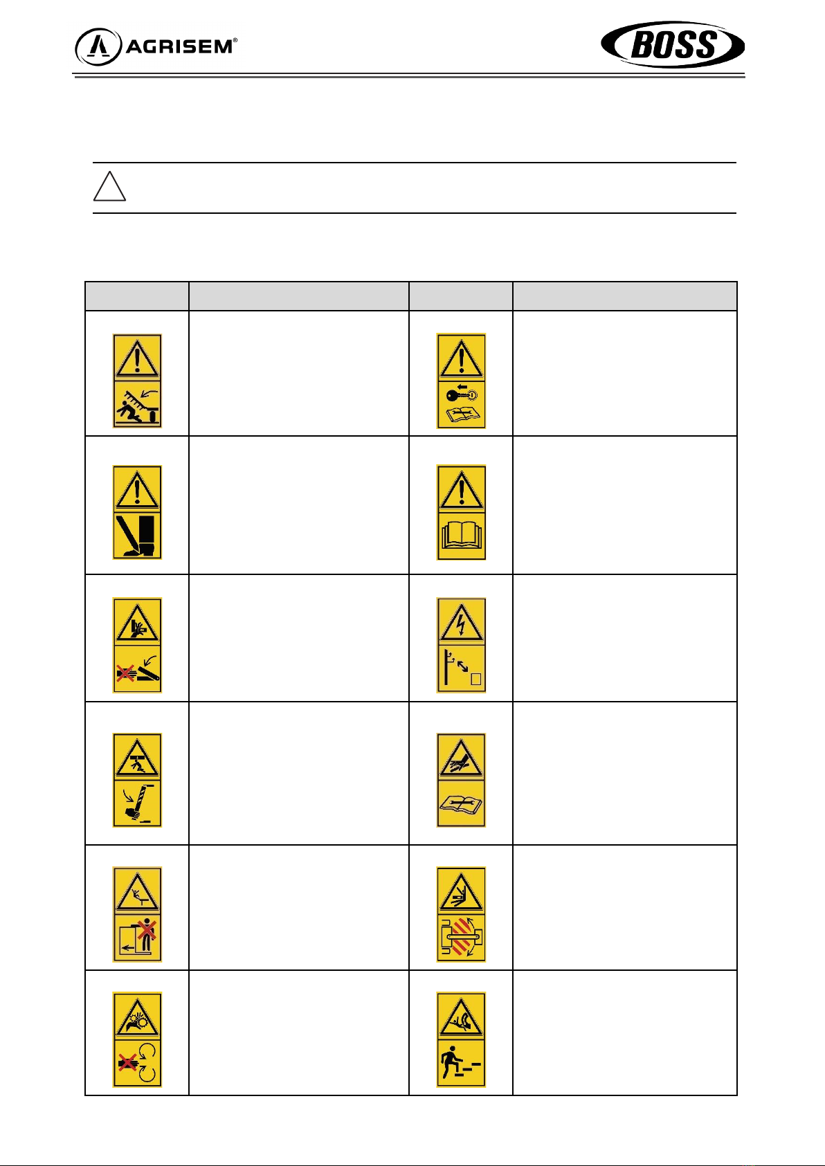
2.16 Safety stickers
2.16.1 Explanation of stickers :
Sticker Description Sticker Description
380135
ETIQ01-627
Stay clear when unfolding.
Keep a safe distance
from any moving parts when
unfolding.
305021
ETIQ01-601
Stop the engine and remove the key.
Stop the engine and remove the
ignition key before carrying out any
maintenance or servicing.
305016
ETIQ01-633
Feet-crushing danger area.
Keep a safe distance from any
moving parts.
355001
ETIQ01-603
Read the user manual.
Read the user manual and safety
instructions before commissioning
and observe them during operation.
355054
ETIQ01-625
Crushing danger area.
Never work in an area where there
is a risk of crushing while parts are
still moving.
355063
ETIQ01-643
Keep a safe distance from power
lines.
Keep a safe distance from high-
voltage
power lines.
355049
ETIQ01-617
Locking device.
Apply the locking device before
any work is carried out.
305064
ETIQ01-641
Hydraulic leakage.
Follow the instructions in the user
manual for maintenance work.
355062
ETIQ01-651
Transporting on the machine.
Never carry passengers on the
machine.
355048
ETIQ01-609
Scanning area.
Stay out of the scanning area.
355035
ETIQ01-655
Rotating parts.
Never put your hands in the area
where the bolt is rotating.
380299
ETIQ01-649
Moving parts.
Never climb on parts that can
rotate. Only use the equipment
intended for climbing.

13
002
Sticker Description
Wheel tightening.
Check the tightness of the wheels after 8 hours of use.
355001
355021
355064
355062
355065
355048
355016
355049
355054
380135
355063 x 2
x 2 355062 380299
305035 x 2
002 x 2
2.16.2 Placement of stickers on the mBoss
2.16.3 Placement of stickers on the Boss
2.16.4 Placement of stickers on Big Boss machines
The safety stickers with the supplement ‘x 2’ are located on both sides of the machine.
Stickers
Stickers
Stickers
Stickers

14
3 Technical specications
3.1 Technical data
3.1.1 mBoss
3.1.2 Boss
Operating width (m) 3 4
Transport width (m) 3 4
Transport height (m) 2.96 3.96
Length (m) 5.60
Weight (kg) 4,150 5,400
Single hopper capacity (l) 1,600
Double hopper capacity (l) 3,200
Triple hopper capacity (l) (+1200 or 2000) 4400 or 5200
Open,lledhopperdims.(m) 0.77 x 0.91
Number of seeding ploughshares 18 16 24 22
Row spacing (cm) 16.7 18.75 16.7 18.75
Transport wheels dims. 500/60R-22.5
Transport wheels dims.
(optional) 710/50R-26.5
Working speed (km/h) 16.7
Max. transport speed
(km/h) 25
Operating width (m) 3 4 4.5 6 7
Transport width (m) 2.99
Transport height (m) 3.23 3.29 3.97 4.45
Length (m) 7.18 – 7.80 (triple hoppers)
Weight (kg) 4,850 5,310 6,240 6,650 7,200
Single hopper capacity (l) 1,200 or 2,000
Double hopper capacity (l) 2,400 or 4,000
Triple hopper capacity (l) 3,600 or 6,000
Open,lledhopperdims.(m) 0.77 x 0.91
Heightoflledhopper(m) 2.63 (1200L hopper ) or 3.12 (2000L hopper)
Number of seeding ploughshares 12 - 16 - 18 16 - 20 - 22
- 24 24 24 - 30 - 32
- 36 28
Row spacing (cm) 16.7 - 18.75
- 20 - 25
16.7 - 18.75
- 20 - 25 18.75 16.7 - 18.75
- 20 - 25 25
Transport wheels dims. 500/60R-22.5
Transport wheels dims.
(optional) 710/50R-26.5
Working speed (km/h) 6 - 15
Max. transport speed
(km/h) 25

15
NOTE:
We reserve the right to make changes as a result of technical developments.
The weight of the coupled implement depends on the equipment; indication with minimum
equipment.
The permitted transport heights and widths on public roads may vary from country to country.
Observe national registration requirements.
3.2 Nameplate
The nameplate with the CE label is located on the machine frame.
3.1.3 Big Boss
Operating width (m) 8 9 10 12
Transport width (m) 2.99
Transport height (m) 4.45
Length (m) 12.5
Weight (kg) 16,900 17,500 18,100 19,500
Single hopper capacity (l) 1,200 or 2,000
Double hopper capacity (l) 2,400 or 4,000
Triple hopper capacity (l) 3,600 or 6,000
Open,lledhopperdims.(m) 0.77 x 0.91
Heightoflledhopper(m) 2.63 (1200L hopper ) or 3.12 (2000L hopper)
Number of seeding ploughshares 32 - 40 - 44 - 48 36 - 46 - 48 - 54 40 - 50 - 56 - 60 48 - 60
Row spacing (cm) 16.7 - 18.75 - 20 - 25 20 - 25
Transport wheels dims. 500/60R-22.5
Transport wheels dims.
(optional) n/a
Working speed (km/h) 6 - 15
Max. transport speed
(km/h) 25
Reference
marker
Description
1 Brand
2 Model / variant / version
3Serialidenticationnumber
4 Date of receipt
5Issueofapprovalbycertication
bodies
6 Total loaded weight
7 Tare weight
8 - 9 Not used

mBoss seed drill 4 m:
16
3.3 Dimensions
BOSS seed drill 4.5m :
BOSS seed drill 3m:
mBoss seed drill 3 m:

17
BOSS seed drill 6m :
BOSS seed drill 7m:
Big Boss seed drill 8 / 9 / 10 / 12m :
Dimensions, see table ‘3.1 Technical data’ 3.1.3 Big Boss
12,500 2,990
4,450

18
Actual value obtained
from the calculation
Permissible value
according to the
user manual
Value x 2 of the permissi-
ble tyre load
MAV
CAV CAR
RAR
3.4 Ballast calculation
The mounting or coupling of implements must not lead to the tractor's permissible gross vehicle weight, permissible
axleloadandtyrespecicationsbeingexceeded.
PV Tractor empty weight.
CAV Empty tractor front axle load.
CAR Empty tractor rear axle load.
MAV Front mass (if present).
RAR Load transfer from the coupled machine
a Distance between the centre of gravity of the front implement or front ballast and the centre of the front axle.
b Tractor wheelbase.
c Distance between the centre of the rear axle and the centre of the rear lower coupling point.
All weight data in (kg)
All measurement data in (m)
Calculation of the minimum ballast at the front :
Calculation of the actual front axle load :
Calculation of the actual total weight :
Calculation of the actual rear axle load :
The calculated values must not exceed the permissible values.
Mini ballast
front
Total weight
Load on front
axle
Load on rear
axle
≥
≥
≥
≥
≥
MAV (min)=
P(total)=
CAV (total)=
CAR (total)=

19
4 Usage
4.1 Coupling
Before coupling the machine, ensure that it has been correctly immobilised.
1. Check the machine and tractor couplings for wear and cleanliness.
2. Move the tractor up to the machine.
3. Couple the machine.
a) Machines with coupling on the lifting arms :
Couple the machine
Lock the catch hooks Tension the stabilisers to prevent lateral movement
Ensure that the level of the linkage is set so that the machine frame is in a horizontal position
Connect the hydraulic brake connector
b) Machines with hitch ring :
Adjust the height of the drawbar so that the machine can be coupled.
Couple the machine.
Insert the bolt and lock it.
Connect the hydraulic brake connector
c) Machines with ball coupling :
Lower the drawbar or cap onto the ball and raise the machine slightly.
Position the clamping frame.
Check and adjust the size of the gap between the clamping frame and the cap.
4. Fold in the support legs and lock them in place with the pin provided.
4.2 Hydraulic connection
The operation of the seed drill requires :
- 1 double-acting hydraulic valve for folding and unfolding the machine's wings.
-1double-actinghydraulicvalvetoraiseandlowertheseedingunitsintheeld.
- 1 double hydraulic valve for the use of markers (optional).
- 1 single-acting to power the hydraulic turbine.
-1freereturn(malein3⁄4)tothetractor'shydraulicoiltankforturbineoilreturn.
Whenusingatractorwithavariableowpumpandintegratedregulators(closedcircuit),thetractor'sregulatormust
be used to adjust the fan speed.
Theoilowraterequiredforaturbinespeedofapproximately4,500rpmis45l/min.
Clean the hydraulic connections before connecting.
Connect the hydraulic hoses that supply the folding system to a double-acting valve.
Connect the hydraulic hoses required to supply the markers to a double-acting control valve.
Connect the free return of the turbine (photo).
Connect the turbine supply to a single-acting valve.
4.3 Electrical connection
1. Plug in the road signal electrical socket.
2. Connect the power supply plug of the regulator (photo)
3. Connect the cigarette lighter socket to the power supply of the touch pad.
!Never operate the valve controlling the turbine without having correctly connected the free return,
otherwise the turbine motor may be damaged.

20
!Do not position yourself under the wing of the seed drill
when removing the pins
Starting up
5.1 Unfolding the seed drill
5.1.1 Boss
1. Remove the safety pins from the wings
2. Activate the corresponding hydraulic control valve until the wings are completely unfolded
!Before unfolding the wings, make sure that the seeding units are in the upper position
5.1.2 Big Boss
1. Manually unlock the wings by removing the locking pins on the main base brackets.
This manual suits for next models
3
Table of contents
Other Agrisem Seeder manuals

Popular Seeder manuals by other brands

Amazone
Amazone Centaya 3000 Special Original operating manual

Billy Goat
Billy Goat OS901SPS owner's manual

Meridian
Meridian 112BST Operator's manual

Maschio
Maschio Gaspardo SP Series Use and maintenance

GREAT PLAINS
GREAT PLAINS 2SNG24 Original instructions

GREAT PLAINS
GREAT PLAINS YP2425F-2470 Feature supplement manual


