Billy Goat OS901SPS User manual

OSSP Owner’s Manual
Part No 351520 1 Form No F020416C
SELF PROPELLED OVERSEEDER Owner's Manual
OS901SPS, OS901SPH
Beginning Serial #: 020416001
Accessories Replacement Parts
Original Instructions
IMPORTANT- READ CAREFULLY BEFORE USE AND KEEP FOR FUTURE REFERENCE
CHARIOT KIT
REEL KIT
Allows the user to ride
behind the unit and
decrease fatigue from
walking.
P/N 351601
Use to replace worn or
damaged reels.
P/N 351603
BLADE KIT
Use to replace worn or
damaged blades on the
reel.
P/N 351610

OSSP Owner’s Manual
Part No 351520 Form No F020416C
2
CONTENTS
SPECIFICATIONS AND SOUND/VIBRATION 3
INSTRUCTION LABELS 4
PACKING CHECKLIST 5
ASSEMBLY 6
OPERATION 7-8
MAINTENANCE & TROUBLESHOOTING 9-10
PARTS LIST 11-22
DECLARATION OF CONFORMITY 23-25

OSSP Owner’s Manual
Part No 351520 Form No F020416C
3
SPECIFICATIONS
OS901SPS OS901SPH
Engine: HP’
9.0 HP (6.7kW)
9.0 HP (6.7kW)
Engine: Model
EX270D50021
GX270K1QA2
Engine: Type
Subaru
Honda
Engine: Fuel Capacity
6.4 qt. (6.1 L)
5.6 qt. (5.3 L)
Engine: Oil Capacity
1.06 qt. (1 L)
1.16 qt. (1.1 L)
Total Unit Weight:
314# (142 kg)
323# (147 kg)
Max. operating slope
15o
20o
Sound test in accordance with
2000/14/EC
104 dB(a)
104 dB(a)
Sound at operators ear
84 dB(a)
84 dB(a)
Vibration at operator position
0.81g (7.95 m/s2)
0.81g (7.95 m/s2)
SOUND
SOUND LEVEL 84 dB(a) at Operators Position
Sound tests were conducted in accordance with 2000/14/EC, and were performed on 10-13-2010 under the conditions listed
below.
Sound power level listed is the highest value for any model covered in this manual. Please refer to serial plate on the unit for
the sound power level for your model.
VIBRATION DATA
VIBRATION LEVEL .81g (7.95m/s2)
Vibration levels at the operator’s handles were measured in the vertical, lateral and longitudinal directions using calibrated
vibration test equipment. Tests were performed on 10-13-2010 under the conditions listed below.
General Conditions: Sunny
Temperature: 73oF (23oC)
Wind Speed: 11 mph (17 kmh)
Wind Direction: South West
Humidity: 27%
Barometric Pressure: 30.34Hg (770 mm Hg)
General Conditions: Sunny
Temperature: 66oF (19oC)
Wind Speed: 3 mph (4.8kph)
Wind Direction: East
Humidity: 30.2%
Barometric Pressure: 29.9Hg (101.3kpa)
104

OSSP Owner’s Manual
Part No 351520 Form No F020416C
4
INSTRUCTION LABELS
The labels shown below were installed on your BILLY GOAT®Overseeder. If any labels are damaged or missing, replace them
before operating this equipment. Item numbers from the Illustrated Parts List and part numbers are provided for convenience in
ordering replacement labels. The correct position for each label may be determined by referring to the Figure and Item numbers
shown.
LABEL DANGER KEEP HANDS LABEL CLUTCH ITEM #142 LABEL TRANS. RELEASE
AND FEET AWAY P/N 500177 ITEM #146 P/N 351507
ITEM #145 P/N 400424
LABEL CAUTION GUARDS LABEL DEPTH GAUGE
ITEM #133 P/N 900327 ITEM #59 P/N 351504
LABEL INSTRUCTIONS SEEDER BOX LABEL SEED METERING
ITEM #56 P/N 351501 ITEM #66 P/N 351503
(pg 12) (pg 12)
ENGINE LABELS
.
SUBARU HONDA
HONDA MOTOR CO. , LTD. MADE IN JAPAN
READ OWNER’S MANUALBEFORE OPERATION.
LIRE LE MANUELD UTILISATEURAVANT USAGE.
VOR INBETRIEBNAHME UNBEDINGHT BEDIENUNGSANLEITUNG DURCHLESEN.
NO UTILIZAR SINANTES NO HABER LEIDO ELMANUAL
WHEN OIL LEVELLOW,
ENGINE STOPS IMMEDIATELY.
OIL ALERT

OSSP Owner’s Manual
Part No 351520 Form No F020416C
5
PACKING CHECKLIST
Your Billy Goat Overseeder is shipped from the factory in one carton.
PUT OIL IN ENGINE BEFORE STARTING
READ all safety instructions before assembling unit.
TAKE CAUTION when removing the unit from the box, the Handle Assembly is attached to the unit and
cables could snag.
Boxing Parts
Checklist
Subaru 9 HP
Honda 9 OHV
Parts bag
P/N-351009
Foot pedal
assembly
PARTS BAG & LITERATURE ASSY
Warranty card P/N- 400972, Owner’s Manual P/N-351520, General Safety and Warnings Manual P/N-100295, Declaration of
Conformity P/N-351508.

OSSP Owner’s Manual
Part No 351520 Form No F020416C
6
ASSEMBLY
NOTE: Items in ( ) can be referenced in the Parts Illustrations and Parts Lists on pages 11-22.
1. UNFOLD the upper handle and slide handle lock loops (item 35) into place to secure the upper handle to the lower.
2. ATTACH the bar of the foot pedal to the bracket located on the engine. Use the lock nut (item 93) from the parts bag.
3. ATTACH the pedal section to the rear of the frame between the two brackets by aligning the holes and inserting the tube
(item 201) from the parts bag.
4. TAP the two pins (item 202) into both ends of the tube installed in step 3, and using pliers, spread the cotter pins to keep
it from coming out.
5. CHECK engine oil level and fill to proper level with engine manufacturers recommended grade of oil. Make sure to adjust
the machine so that the engine is level during checking. See engine manufacturers’ instruction manual.
6. CONNECT spark plug wire.
93
201
202

OSSP Owner’s Manual
Part No 351520 Form No F020416C
7
OPERATION
ADJUSTING BLADE DEPTH
The depth of the blades can be raised or lowered by rotating the knob located at the rear of the
machine. The relative depth of the blades can be gauged by using the depth scale located on
the rear of the machine and the bar next to it. (See Fig. 1)
NOTE: Items in ( ) can be referenced in the Parts Illustrations and Parts Lists on pages 11-22.
FOLDING HANDLE
This unit is equipped with a folding upper handle for easier storage and transportation. The handle can be folded by sliding the
handle lock loops (item 35) up. This releases the upper handle, allowing it to be folded over the unit.
BLADE POSITION & DEPTH CONTROL LEVER
The blades can be raised or lowered into the ground by the height adjustment foot pedal at the
rear of the unit. The blades will be in lowered position when the foot pedal is unlocked from the
bracket and will be in transport position when the pedal is locked to the bracket. See Fig. 2 & 3
for operation. The resulting blade depth can be adjusted higher or lower.
VERTI-CUTTING OPERATION
SET DEPTH: With engine off, set the raking depth so that the blades just touch on a flat surface (i.e. driveway, or sidewalk).
ENGAGE BLADES: Push the Reel Lever down on the operator handle (upper left side). NOTE: When engaging the blades in
heavy load conditions (i.e. heavy thatch, or very uneven turf), push down on the operator handle lifting the front wheels slightly.
Engage the blades. Slowly lower the unit into the turf.
SLICE: Verti-cut a small test area and examine the results. Some thatch and cut stems should be removed and deposited on top
of the healthy grass. Grass runners should be cut and ready for removal. If excessive damage occurs to healthy grass, adjust
the blade depth to decrease damage. Continue raking the yard, working in one direction (i.e. north-south, or east-west). NOTE: If
a large drop in engine RPM occurs, or bounces during operation, the blade depth is set too low.
REMOVE THATCH/STEMS: After verti-cutting, a layer of thatch and cut stems will be deposited over the top of the lawn. We
suggest the use of a lawn vacuum or wheeled blower for collection and removal of the thatch/stems.
OVERSEEDING OPERATION
DRY: Be sure grass is dry. Wet conditions can cause increased damage to healthy grass.
SEED:Spread grass seed according to the seed suppliers directions (e.g. 10 lbs. per 1000 ft2[4.5 kg. per 93 m2]) Adjustments to
the seed drop is located on the front of the unit on the seed dial and should be used in conjunction with the seed chart on the
console.
SET DEPTH: With engine off, set the raking depth so that the blades reach 1/4"-1/2" (6-12 mm) below a flat surface (i.e. driveway,
or sidewalk).
ENGAGE REEL AND SEED DROP: Push down on the reel lever on the operators handle. NOTE: When engaging the reel in heavy
load conditions (i.e. heavy thatch, or very uneven turf), push down on the operators handle lifting the front wheels slightly. Engage
the reel. Slowly lower the unit into the turf.
SLICE: Run machine over the area that has been seeded to incorporate the seed into the soil. If excessive damage occurs to
healthy grass, adjust the blade depth to decrease damage. Continue raking the yard, working in one direction (i.e. north-south, or
east-west). NOTE: If a large drop in engine RPM occurs, or bounces during operation, the blade depth is set too low.
WATER/FERTILIZE: After the seed has been worked into the soil, water and fertilize according to the seed supplier’s directions.
Pressing on the outside tabs of the pedal will allow it to unlock
from the bracket and lower into position. (See Fig. 2)
Pressing on the center of the pedal and pushing it into the bracket
will allow it to be locked in transport position. (See Fig. 3)
Fig. 1
Fig. 2
Fig. 3

OSSP Owner’s Manual
Part No 351520 Form No F020416C
8
Fig. 6
Fig. 5
ADJUSTING SEED RATE
INSTRUCTION LABEL P/N 351501
To set the seed flow rate, loosen the knob on the indicator dial and turn it to the
corresponding stop setting on the seed application chart (below or on the console) for the
type and amount of seed being used. (See Fig. 4)
*****TIPS*****
Before beginning, it is best to evaluate the condition of the lawn by cutting one or more core samples from area to be treated. A core can
be cut using a piece of PVC, or metal pipe. Hammer the pipe into the ground, remove it, push the core out of the pipe and inspect it to
determine the depth of thatch in your yard.
MOW
Mow the lawn to its normal cut height. Be sure grass is dry. Wet conditions can cause increased damage to healthy grass.
INSPECT
Check the lawn before beginning work. Remove all rocks, wire, string, or other objects that can present a hazard during work.
IDENTIFY
Mark all fixed objects to be avoided during work, such as sprinkler heads, water valves, buried cables, or clothes line anchors, etc.
THATCH
Thatch is a dense layer of dead grass, clippings, and roots that builds up over time at the base of the lawn preventing air, water, and
fertilizer from reaching the soil. This can cause shallow root development and make a lawn more susceptible to drought and disease.
Thatch also provides an ideal environment for insects to hide and multiply. Periodic removal of thatch will keep your lawn in good health.
HEAVY THATCH
Lawns with an excessive amount of thatch will require multiple treatments for effective removal. Trying to remove excessive thatch
(greater than 3/4"[19 mm] deep) in one treatment will damage or destroy the living part of the lawn. It is best to remove heavy thatch in
seasonal treatments (i.e. spring, and fall).
SLOPES
Rake slopes across not up and down the slope. This is much easier and safer for the operator and is better for the lawn. Raking across
will help to reduce runoff during watering and allow the sloped ground to hold more seed, fertilizer, and water. The unit’s maximum
operating slope is 35% or 19°.
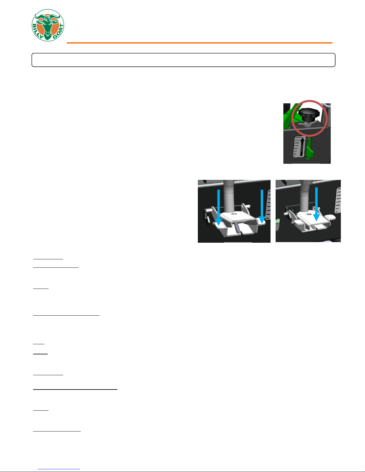
DEPTH
The wide range of depth adjustment on your unit is provided to allow for blade wear. Setting the reel deeper will not produce better results.
The flail reel is intended to be set so it just touches the surface on flat ground. The slicing reel should be set even with the ground for verti-
slicing work, and set to a maximum 1/2" depth for overseeding. Setting the reel deeper will only result in premature wear on the unit (i.e.
failed belt). If you desire to work the ground deeper than the above guidelines, it should be done gradually in multiple passes.
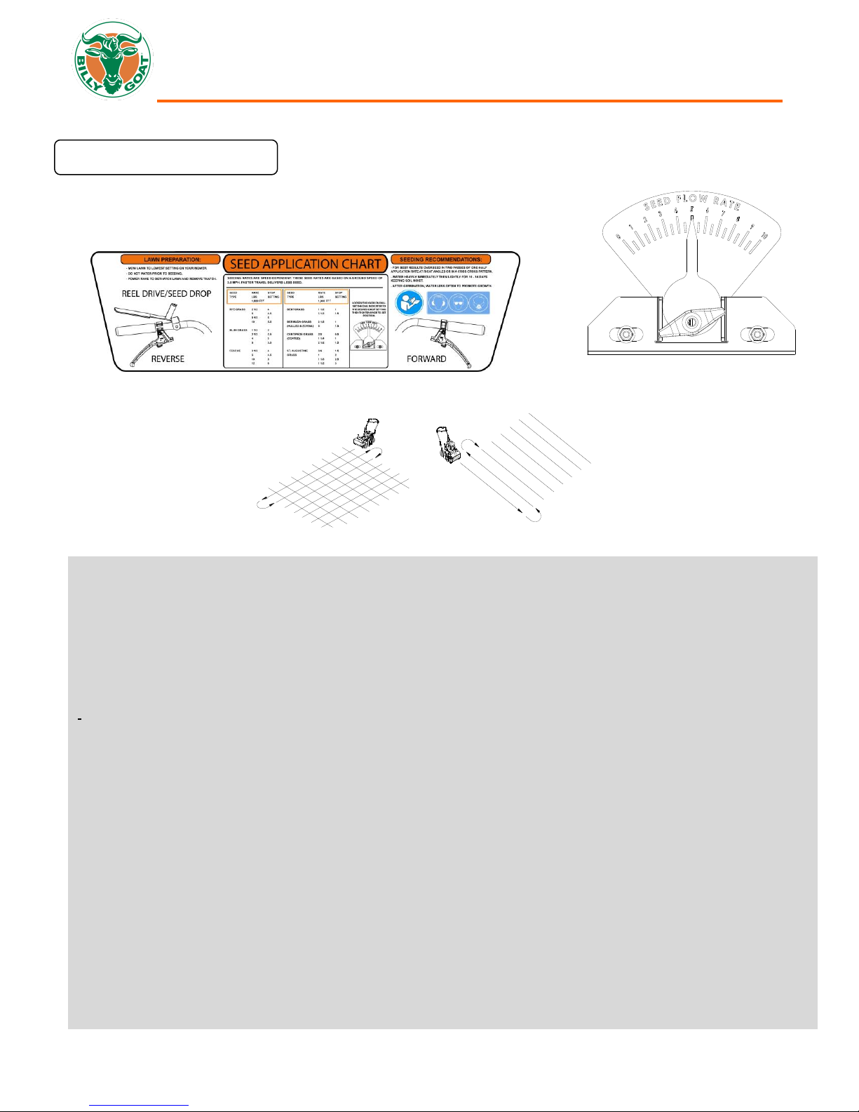
SLICING / OVERSEEDING: Mow the lawn to shorter than the normal cut height before starting (i.e. approximately 2" tall for fescue grass).
For the best result, slice/overseed in criss-cross pattern (See Fig. 5 & 6).
Fig. 4

OSSP Owner’s Manual
Part No 351520 Form No F020416C
9
MAINTENANCE
NOTE: Items in ( ) can be referenced in the Parts Illustrations and Parts Lists on pages 11-22.
PERIODIC MAINTENANCE
Periodic maintenance should be performed at the following intervals:
Maintenance Operation
Every Use (daily)
Every 25 Hours
Inspect for loose, worn or damaged parts
Check engine oil
Inspect belts
Engine (See Engine Manual)
Grease bearings
Inspect and clean engine air filter
Oil height adjustment linkage
SLICING BLADE WEAR
1. Wait for engine to cool and disconnect spark plug.
2. Close fuel valve on engine (if available).
3. Lean unit back onto lower handles and secure in place.
4. Inspect blades for wear and immediately replace any deformed or cracked blades. Measure the overall diameter of the
blade.
5. If blades are warped or the diameter of the blade is 6.75" (171 mm) in length, they must be replaced. NOTE: We
recommend replacing all the blades at once.
ENGINE BELT REPLACEMENT
1. Wait for engine to cool and disconnect spark plug.
2. Place the rear of the unit on blocks.
3. Remove the right rear tire (item 11) and spring (item 155) attaching the housing to the frame.
4. Remove three screws (item 114) holding the belt guard (item 19) in place.
5. Remove the four screws (item 107) holding the mule drive assembly (item 60) in place.
6. Remove the belt (item 14) by rotating the mule drive pulley and walking it out of the groove, and remove the mule
assembly leaving the belt on the transmission.
7. Remove the carriage bolt and nuts holding the right bearing on the jackshaft. Do not remove the bearing and pulley.
8. Remove the belt guard (item 58) by removing the three screws (item 114).
9. Walk the belt off of the crankshaft pulley, and then slide it down the jackshaft to the bearing hole. This will allow the belt
to be slid around the mule pulley.
10. Replace the belt by feeding it into the hole and around the pulley where the old one was removed. Make sure it is seated
in the jackshaft pulley and then walk it onto the crankshaft pulley making sure it is inside the belt fingers.
11. Reattach the bearing and tighten the hardware securely.
12. Reattach the mule drive and belt, making sure that the belt is seated properly in the transmission pulley and the mule
drive assembly.
13. Check the idler tension on the belt when the drive lever is engaged, if it is too loose, the spring (item 82) holding the idler
arm will need to be replaced.
14. Reattach the guards, tire, spring and spark plug and make sure of proper operation.

OSSP Owner’s Manual
Part No 351520 Form No F020416C
10
TROUBLESHOOTING
MULE BELT REPLACEMENT
1. Wait for engine to cool and disconnect spark plug.
2. Place the rear of the unit on blocks.
3. Remove the right rear tire (item 11) and spring (item 155) attaching the housing to the frame.
4. Remove (3) screws (item 114) holding the belt guard (item 19) in place.
5. Remove the four screws (item 107) holding the mule drive assembly (item 60) in place. This will allow access to the belt.
6. Remove the belt (item 14) by rotating the mule drive pulley and walking it out of the groove, and then sliding it off of the
transmission. Discard old belt.
7. Install new belt using same procedure to walk the belt into the groove, making sure it is seated fully in all pulleys. Reattach
the mule drive assembly.
8. With new belt installed, pull the drive levers up and make sure the idler pulley puts tension on the cable. The proper
adjustment should have the drive lever fully engaged and the belt should be snug on the pulleys.
9. Re-install the belt guard, spring, and tire, then reattach the spark plug.
REEL BELT REPLACEMENT
1. Wait for engine to cool and disconnect spark plug.
2. Remove two screws (item 38) holding the belt guard (item 20) in place
3. Remove the belt (item 17) by rotating the reel pulley (item16) and walking it out of the groove. Discard old belt.
4. Install new belt using same procedure to walk the belt into the groove, making sure that it is inside the belt fingers.
5. With new belt installed, push the reel drive lever down and make sure the idler pulley puts tension on the cable. The proper
adjustment should have the blade lever fully engaged and the belt should be snug on the pulleys.
6. Re-install the belt guard and reattach the spark plug.
Problem Possible Cause Solution
Abnormal vibration
Damaged or missing blades. Loose
handle bolts. Loose engine bolts.
Stop work immediately. Replace any
damaged or missing blades. Tighten all
loose nuts and bolts.
Engine stalls or labors when
raking
Blades set too deep into ground.
Raise blades so that they just touch
the ground on a level surface.
Engine will not start
Stop switch off (Honda only). Throttle
in off position.
Check choke position.
Out of gasoline or bad, old gasoline. Check gasoline.
Spark Plug wire disconnected. Connect spark plug wire.
Gas valve off. Turn on gas valve.
Dirty air cleaner.
Clean or replace air cleaner. Contact a
qualified service person.
Engine is locked, will not pull
over
Debris locked against reel, or drive
pulleys. Engine problem.
Pull spark plug wire and remove debris.
Contact an engine servicing dealer for
engine problems.

OSSP Owner’s Manual
Part No 351520 Form No F020416C
11
SLICING REEL ASSY P/N 351603
ITEM NO DESCRIPTION PART NO. QTY
1 SHAFT VERTICUTTING REEL OS900SP 351111 1
2 BLADE VERTICUT OS900SP 351305 11
3 SPACER PM REEL OS900SP 351261 10
4 SPACER HARDENED REEL OS900SP 351297 1
5 SPRING DISC 7/8" ID 351298 1
6 NUT 7/8"-14 NC 350341 1
6
5
4
2
3
1
45°
EACH BLADE SHOULD BE ROTATED CLOCKWISE 45 DEGREES. USE THE HOLE
IN THE BLADE TO SET ORIENTATION.
ORIENTATION HOLE

OSSP Owner’s Manual
Part No 351520 Form No F020416C
12
OSSP ENGINE ASSEMBLY PARTS DRAWING

OSSP Owner’s Manual
Part No 351520 Form No F020416C
13
OSSP ENGINE ASSEMBLY PARTS LIST
OS901SPH
OS901SPS
ITEM NO. DESCRIPTION PART NO. QTY PART NO. QTY
1 ENGINE HONDA 9HP 430287 1 - -
ENGINE SUBARU 9HP - - 351299 1
3 ENGINE BASE WA 351125 1351125 1
7 JACKSHAFT WA 351107 1351107 1
18 BELT GATES #8954-0298 351211 1351211 1
50 ENGINE BRACKET WA 351121 1351121 1
51 LINKAGE FOOT CONTROL WA 351122 1351122 1
57 BRACKET GUARD BELT UPPER 351203 1351203 1
58 GUARD BELT UPPER OS900SP 351116 1351116 1
78 PULLEY IDLER 4" OD X 3/8 BORE 500113 1500113 1
80 ARM IDLER WA UPPER 351113 1351113 1
81 PULLEY 3.50" OD X 1.00" BORE 351296 1351296 1
82 SPRING IDLER UPPER 351275 1351275 1
91 BOLT SHOULDER 1/2" X 2" 520031 1520031 1
93 NUT LOCK 5/16"-18 8160002 78160002 7
95 WASHER SPLIT LOCK 8177011 68177011 6
96 WASHER LOCK 7/16' S/T MED 8177013 18177013 1
99 SCREWCAP 7/16"-20 X 1" HCS GR. 8 W/PATCH 510213 1510213 1
101 SCREWCAP 5/16"-24 X 1" GR 8 W/PATCH 400164 6400164 6
102 SCREWCAP 3/8"-16 X 1 3/4" HCS ZP 8041053 18041053 1
108 WASHER 5/16 FLAT 8171003 88171003 8
112 BOLT CARRIAGE 5/16"-18 X 1 1/2" ZP 8024042 18024042 1
113 LOCK NUT 3/8-16 8160003 28160003 2
114 SCREW SELF TAP 1/4"-20 X 5/8" HWH TYPE F 890359 3890359 3
116 WASHER 3/8" SAE 8172009 28172009 2
118 NUT FLANGE 5/16-18 ZP 350346 2350346 2
119 PLATE IMPELLER WASHER PB110 850443 1850443 1
121 SPACER 1.25 OD X 1.010 ID X .938 THK 351413 2351413 2
133 LABEL DANGER 900327 2900327 2
134 SCREWCAP 5/16"-18 X 1 3/4" HCS ZP 8041031 58041031 5
135 KEY SQ 1/4" X 1" 9201113 19201113 1
196 ENGINE BASE WA OS900SP W/LABELS 351612 1351612 1
199 LABEL MADE IN U.S.A. 520116 1520116 1

OSSP Owner’s Manual
Part No 351520 Form No F020416C
14
OSSP REEL/REEL DRIVE ASSEMBLY PARTS DRAWING

OSSP Owner’s Manual
Part No 351520 Form No F020416C
15
OSSP REEL/REEL DRIVE ASSEMBLY PARTS LIST
OS901SPH OS901SPS
ITEM NO. DESCRIPTION PART NO. QTY PART NO. QTY
3 ENGINE BASE WA 351125 1351125 1
4 HOUSING VERTICUTTER WA OS900SP 351101 1351101 1
5 FRAME SUPPORT OS900SP WA 351126 1351126 1
13 BEARING 3/4" CAST FLANGE W/ZERK 350209 2350209 2
16 PULLEY 0.75" ID X 4" 4L SECTION 351210 2351210 2
17 BELT 4L 351213 2351213 2
20 GUARD REEL BELT OS900SP 351117 1351117 1
21 LABEL DECAL SM CIRCLE 890456 1890456 1
38 SER HEX WASHER 3/8" - 16 791080 2791080 2
41 WASHER 1.125 OD X .344 ID X 10 GA 441150 1441150 1
49 REEL ASSY OS900SP 351012 1351012 1
54 GUARD BEARING REEL OS900SP 351206 1351206 1
55 SPACER SEED BOX AXLE OS900SP 351408 1351408 1
68 DEFLECTOR RUBBER OS900SP 351269 1351269 1
69 BAR CLAMP DEFLECTOR 351268 1351268 1
76 ARM IDLER WA REEL ENGAGE 351112 1351112 1
77 PULLEY 350114 2350114 2
91 BOLT SHOULDER 1/2" X 2" 520031 1520031 1
93 NUT LOCK 5/16"-18 8160002 48160002 4
95 WASHER SPLIT LOCK 8177011 18177011 1
103 SCREWCAP 5/16-18 X 3 1/2" 8041038 28041038 2
104 SCREWCAP 3/8"-16 X 1" 8041050 48041050 4
108 WASHER 5/16" FC 8171003 28171003 2
118 NUT FLANGE 5/16-18 ZP 350346 4350346 4
120 NUT LOCK 3/8-16 LT WT THIN ZP 8161042 58161042 5
124 SPRING IDLER MULE DRIVE 351295 1351295 1
127 SER HEX WASHER FLNG SCREW 5/16"-18 X 3/4" 351264 6351264 6
129 BOLT CARRIAGE 5/16"-18 X 3/4" ZP 8024039 48024039 4
135 KEY 3/16" SQ X 1 1/4" 9201080 19201080 1
138 CABLE CLUTCH SEEDING CONTROL 351221 1351221 1
147 PIN CLEVIS 1/4" X .50" 440124 1440124 1
150 PIN CLIP HITCH 0.051" X 3/4" 440193 1440193 1
187 SCREWCAP 3/8"-16 X 2 1/2" ZP 8041056 18041056 1
191 SCREWCAP 5/16"-24 X 1" GR.8 ZP W/PATCH 400164 1400164 1
193 GUARD REEL BELT OS900SP W/LABELS 351607 1351607 1

OSSP Owner’s Manual
Part No 351520 Form No F020416C
16
OSSP HANDLE ASSEMBLY PARTS DRAWING

OSSP Owner’s Manual
Part No 351520 Form No F020416C
17
OSSP HANDLE ASSEMBLY PARTS LIST
OS901SPH
OS901SPS
ITEM NO. DESCRIPTION PART NO. QTY PART NO. QTY
5 FRAME SUPPORT OS900SP WA 351126 1351126 1
28 PLUG TUBE INSERT 1.25 OD 791056 2791056 2
29 HANDLE FOLDING OS900SP 351406 1351406 1
30 BUMPER RECESS 360298 1360298 1
31 BRACKET CONSOLE OS900SP 351208 1351208 1
32 GRIP HANDLE 500267 2500267 2
33 PLUG TUBE INSERT 1" OD 890132 2890132 2
34 CONTROL MAGURA OS900SP 351209 2351209 2
35 LOOP FOLDING HANDLE 351231 2351231 2
50 ENGINE BRACKET WA 351121 1351121 1
51 LINKAGE FOOT CONTROL WA 351122 1351122 1
52 PIN CLEVIS 3/8 X 2.125 520120 2520120 2
53 RETAINER 3/8" BOLT PUSH NUT 360279 2360279 2
56 LABEL INSTRUCTION OS900SP 351501 1351501 1
67 PEDAL SERVICE KIT 351615 1351615 1
70 LEVER CLUTCH/SEED DROP 351212 1351212 1
72 GRIP LEVER 0.125" X 1" X 5" ORANGE 500379 1500379 1
93 NUT LOCK 5/16"-18 8160002 58160002 5
102 SCREWCAP 3/8"-16 X 1 3/4" HCS ZP 8041053 28041053 2
107 SCREWCAP 3/8"-16 X 3" HCS ZP 8041058 48041058 4
110 BOLT CARRIAGE 3/8"-16 X 2" ZP 8024062 28024062 2
113 LOCK NUT 3/8-16 8160003 98160003 9
114 SCREW SELF TAP 1/4"-20 X 5/8" HWH TYPE F 890359 1890359 1
115 WASHER 1/4" SAE 8172007 18172007 1
117 LOCK NUT 1/4-20 8160001 18160001 1
128 TY WRAP 900407 2900407 2
129 BOLT CARRIAGE 5/16"-18 X 3/4" ZP 8024039 28024039 2
131 SCREWCAP 1/4"-20 X 1" HCS ZP 8041006 18041006 1
136 CABLE SPEED CONTROL RT 351219-S 1 351219 1
137 CABLE SPEED CONTROL LFT 351271-S 1 351271 1
138 CABLE CLUTCH SEEDING CONTROL 351221 1351221 1
140 LABEL LOGO OS900SP 351500 1351500 1
141 BOLT SHOULDER 3/8" X 1 1/4" 360284 1360284 1
142 LABEL CLUTCH BLADE 500177 1500177 1
144 WASHER 3/8 FC 8171004 12 8171004 12
194 BRACKET CONSOLE OS900SP W/LABELS 351605 1351605 1
200 RELEASE PEDAL WA 351124 1351124 1
201 SHAFT INNER PIVOT 351421 1351421 1
202 PIN COTTER 1/8" X 1" ZP 8197031 28197031 2
204 BRACKET PIN CATCH 351321 1351321 1
205 BOLT SHOULDER 3/8" DIA X 3.25 LG BLK OX 351316 1351316 1
206 SPRING PEDAL RELEASE 351309 1351309 1
208 HANDLE W/GRIP RIGHT OSSP SERVICE 351618 1351618 1
209 HANDLE W/GRIP LABEL LEFT OSSP SERVICE 351619 1351619 1

OSSP Owner’s Manual
Part No 351520 Form No F020416C
18
OSSP SEED BOX ASSEMBLY PARTS DRAWING

OSSP Owner’s Manual
Part No 351520 Form No F020416C
19
OSSP SEED BOX ASSEMBLY PARTS LIST
OS901SPH
OS901SPS
ITEM NO. DESCRIPTION PART NO. QTY PART NO. QTY
5 FRAME SUPPORT OS900SP WA 351126 1351126 1
6 SEED BOX WA 351103 1351103 1
10 FRONT WHEEL 14" ASSY 351013 2351013 2
12 BEARING & FLANGETTE ASSY 850232 4850232 4
27 AXLE SEED BOX 351223 1351223 1
44 WHEEL PADDLE SEED WA 351105 1351105 1
45 PLATE SEED CONTROL OS900SP 351220 1351220 1
46 BRACKET CONTROL SEED RATE 351222 1351222 1
48 SPRING EXTENSION .5 X 5.00 351303 1351303 1
55 SPACER SEED BOX AXLE OS900SP 351408 2351408 2
63 SPACER SEED PLATE OS900SP 351253 8351253 8
64 DIAL SEED INDICATOR 351265 1351265 1
65 KNOB 5/16"-18 X 5/8" FLUTED 400339 1400339 1
66 LABEL SEED FLOW RATE 351503 1351503 1
83 CLAMP ROUTING FUEL LINE 791070 1791070 1
100 SCREW 1/4" - 20 X .75 HWH 8041004 88041004 8
115 WASHER 1/4" SAE 8172007 88172007 8
117 LOCK NUT 1/4-20 8160001 88160001 8
125
NUT 5/16"-18 SER HEX WASHER FLNG ZP
350346 8350346 8
129 BOLT CARRIAGE 5/16"-18 X 3/4" ZP 8024039 88024039 8
138 CABLE CLUTCH SEEDING CONTROL 351221 1351221 1
145 LABEL WARNING OPEI 400424 1400424 1
147 PIN CLEVIS 1/4" X .61 350399 1350399 1
148 LABEL BADGING OS900SP 351505 1351505 1
149
WASHER LOCK 5/16" TWISTED TOOTH HEAVY
430298 2430298 2
150 PIN CLIP HITCH 0.051 X 3/4" 440193 1440193 1
151
BOLT CARRIAGE 5/16"-18 X 1 1/4" ZP
8024041 18024041 1
152 SCREWCAP 5/16"-18 X 3/4" HCS ZP 8041026 28041026 2
153 NUT LOCK 5/16"-18 LT WT TH ZP 8161041 18161041 1
154 WASHER FENDER 5/16" 8172020 28172020 2
192 SEED BOX WAS OS900SP W/LABELS 351604 1351604 1
207 SEED BOX SERVICE KIT 351616 1351616 1
211 SEED BOX BONNET 351344 1351344 1

OSSP Owner’s Manual
Part No 351520 Form No F020416C
20
OSSP TRANSMISSION ASSEMBLY PARTS DRAWING
Other manuals for OS901SPS
1
This manual suits for next models
1
Table of contents
Other Billy Goat Seeder manuals
Popular Seeder manuals by other brands

horsch
horsch Maestro 16 SW operating instructions

HE-VA
HE-VA Terra-seeder Series operating instructions

Land Pride
Land Pride 313-308M Operator's manual

Landoll
Landoll Brillion SSP4 Operator's manual

Husqvarna
Husqvarna DT22 Operator's manual

Prodana Seeds
Prodana Seeds Proseeder HP600 operating instructions