AGROFROST FrostGuard Basic B20 Installation and operation manual

~ 1 ~
Frostguard - Operating & Maintenance Instructions –www.agrofrost.eu
Operating & Maintenance Instructions
FrostGuard Basic B20 & B25
It’s strictly forbidden to operate the FrostGuard
if you haven’t read this manual.
Year of construction: ...................
Type: B20 / B25
Serial number: ..................................
Make life easy: buy our AGROFROST Frost Alarm !
This manual must be used according the European legislation. It must be considered as a part of the machine. The
manual must be kept with the machine until the final dismantle as described in the European legislation. The purpose
of this manual is to help use and maintain the FrostGuard safely.
The user manual must be kept by the owner or the user on a safe, dry and sun protected place on the working area. It
must always be available to consult. When the manual is damaged, the user must ask Agrofrost for a new one.
Copyright AGROFROST NV 2017.
All rights are strictly preserved. Reprinting, coping, changing, republishing and disclosure are strictly forbidden
without recognition of Agrofrost SA.
Furthermore, Agrofrost SA has the right to change this publication and fulfil changes to the content without
preannounce of such changes or rework.

~ 2 ~
Frostguard - Operating & Maintenance Instructions –www.agrofrost.eu
POINTS OF ATTENTION IN THIS MANUAL
Hint: to give suggestions and advice to ease certain tasks
Attention: a remark with extra information to call your
attention for possible problems
Warning: to call your attention for avoiding danger
ABOUT THE USERS OF THE FROSTGUARD
▪Required user characteristics.
Persons allowed to drive a tractor by law and familiar with the driving of a tractor may operate the
FrostGuard. They must be at least 18 years old and be able of all their physical and psychical
capacities. They must read this manual before using the FrostGuard.
Someone who has not read this manual cannot use the FrostGuard safely.
▪The profile of the user.
This user manual is created for two main groups:
-The user: the person who operates the FrostGuard
-The mechanic: the person who does the assembling, maintenance and repairs
Members of both groups must read this manual attentively before using the FrostGuard and before
doing any repairs or maintenance on the FrostGuard.

~ 3 ~
Frostguard - Operating & Maintenance Instructions –www.agrofrost.eu
1INTRODUCTION .......................................................................................................................................4
1.1 Intended conditions of use of the FrostGuard ..................................................................................................4
1.2 Improper use of the FrostGuard .......................................................................................................................4
1.3 Positioning the FrostGuard in the orchard, vineyard or field...........................................................................4
1.4 When to start? –When to stop? .......................................................................................................................4
2SAFETY........................................................................................................................................................5
2.1 Important: not to be used in closed areas .........................................................................................................5
2.2 Safety and health risks: residual risk................................................................................................................5
2.3 Safety precautions............................................................................................................................................6
2.4 Safety advice on maintenance, repairs and storage..........................................................................................6
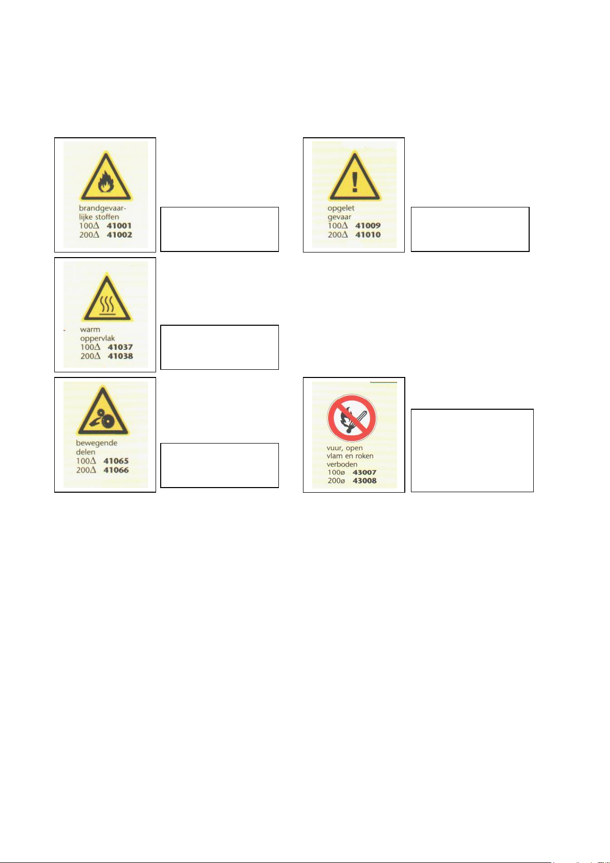
2.5 Explanation pictograms....................................................................................................................................7
3TRANSPORT AND STORAGE.................................................................................................................8
3.1 Transport..........................................................................................................................................................8
3.2 Storage .............................................................................................................................................................8
4FIRST USE AND PREPARATION...........................................................................................................9
4.1 First use............................................................................................................................................................9
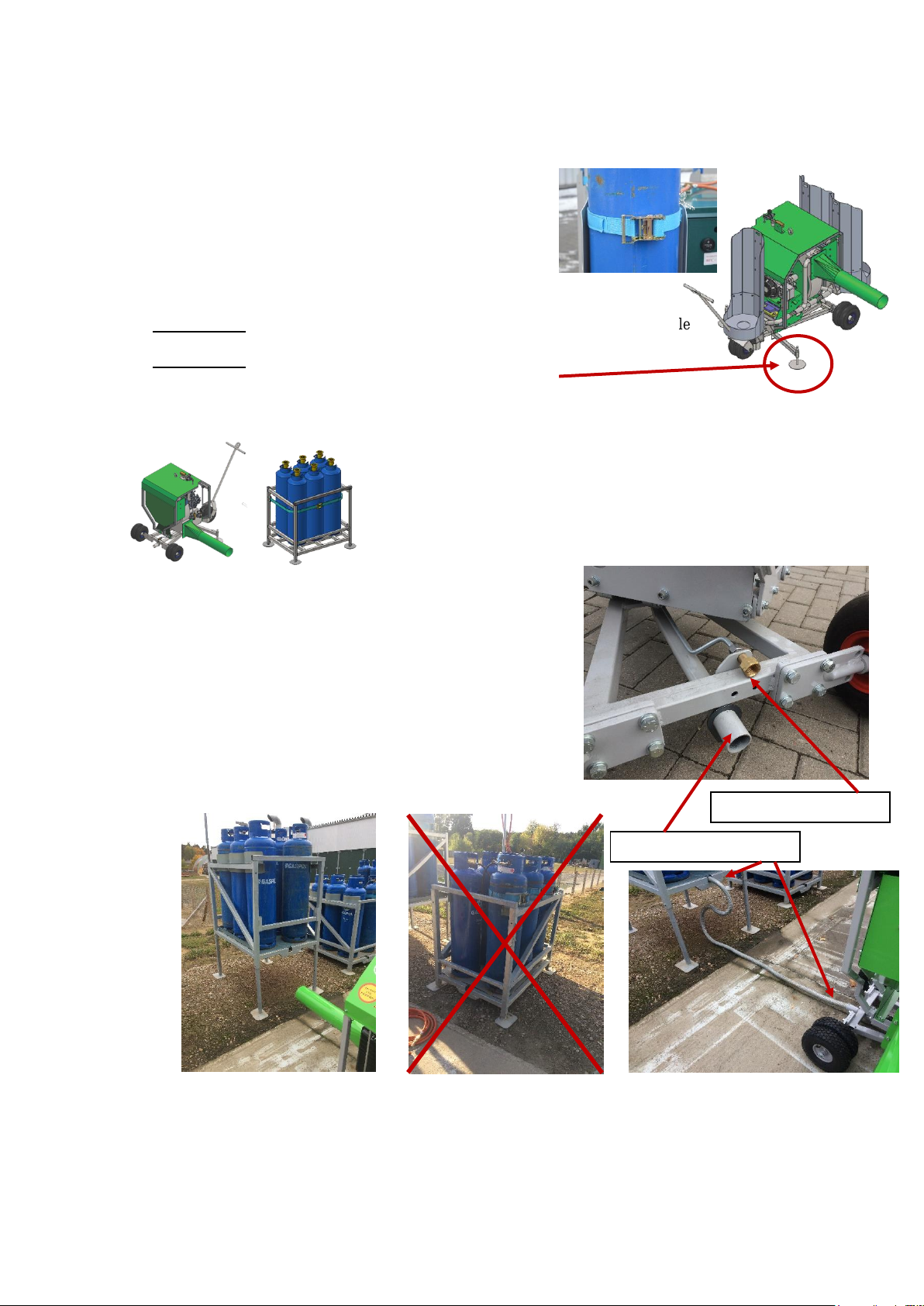
4.2 Set up the FrostGuard with 3 gas cylinder holders on the machine –B25 only.............................................10
4.3 Set up the FrostGuard with container for 5 or 6 gas cylinders –B20 only. ...................................................10
4.4 Set up the FrostGuard with support for 5 or 10 gas cylinders –B20 only. ....................................................11
4.5 Set up the FrostGuard with a gas tank of 300 kg, 500 kg or bigger. ..............................................................11
4.6 Setting the gas pressure..................................................................................................................................11
5OPERATING THE FROSTGUARD BASIC..........................................................................................12
5.1 The controls....................................................................................................................................................12
5.2 Start up and stop Procedure............................................................................................................................12
5.2.1 The Main Control Box..........................................................................................................................12
5.2.2 Starting Procedure. ...............................................................................................................................13
5.2.3 Stopping Procedure...............................................................................................................................14
5.3 During operation ............................................................................................................................................14
5.4 Replacing the gas cylinders during operation ................................................................................................14
6MAINTENANCE –CLEANING .............................................................................................................15
6.1 Cleaning.........................................................................................................................................................15
6.2 Maintenance...................................................................................................................................................15
6.2.1 Burner...................................................................................................................................................15
6.2.2 Engine...................................................................................................................................................15
6.3 Warranty –Scrapping –Spare parts list.........................................................................................................15
6.3.1 Warranty...............................................................................................................................................15
6.3.2 Scrapping..............................................................................................................................................15
6.3.3 Parts list ................................................................................................................................................15
7EC DECLARATION OF CONFORMITY .............................................................................................16

~ 4 ~
Frostguard - Operating & Maintenance Instructions –www.agrofrost.eu
1Introduction
1.1 INTENDED CONDITIONS OF USE OF THE FROSTGUARD
The FrostGuard is a rotating motor driven machine equipped with a powerful fan and a gas burning installation on the
side. It generates a lateral laminar flow of hot air to treat crops and trees with.
The FrostGuard may only be used outdoors where there is natural ventilation.
At the end of the season, the FrostGuard needs to be stored indoor with the propane bottles removed from the machine.
The propane bottles must be stored outside, according the prescriptions of the fire insurance company.
1.2 IMPROPER USE OF THE FROSTGUARD
The FrostGuard may not be used indoors or outdoors in a closed area without natural ventilation.
It is strictly prohibited to use the machine if not all safety requirements as described in Chapter 2, are complied.
The FrostGuard cannot be used, when one or more of the following parts are missing, loose, damaged or incomplete:
-Air outlet
-A fully loaded battery
Furthermore, it is strictly prohibited:
- to use the FrostGuard on slopes with gradients of more than 15%;
- to carry a charge of any kind in any circumstances on the machine;
- to transport persons or loads on the machine;
- to weld or to make any changes whatsoever on the original design of the FrostGuard.
1.3 POSITIONING THE FROSTGUARD IN THE ORCHARD, VINEYARD OR FIELD
Ask your dealer for the ideal setup of the machines, or send a plan of your orchard/vineyard by e-mail to
[email protected]e. Agrofrost will send you back instructions for the ideal set up.
•Orchards
The distances to respect between multiple machines depend on the density of the trees.
If trees are planted 4 x 4 or 4 x 5 or 5 x 5 or … the FrostGuard will protect a round area of approx. 1 hectare.
If trees are planted 0.5 x 3 or 1 x 3.5, the machine will protect an oval area of approx. 70 x 110 m
•Vineyards
In vineyards, we recommend keeping a distance between the machines of 80 meters.
Be aware that vines that are very close to the ground are more difficult to protect than vines of which the lowest
buds/leaves are at a height of 60 or 80 cm.
It’s always helpful to put 1 row of paraffin candles on the wind side. When temperatures drop below -3 °C, or
in case of wind, it’s very helpful to put one row of candles on the complete outside of the vineyard.
1.4 WHEN TO START? –WHEN TO STOP?
The starting temperature depends on the flowering stage.
Once the buds are in balloon stage or in full flowering, it’s very important that the machine
is started up before the wet temperature drops below 0 °C (+0,3 °C).
When the wet temperature outside the treated orchard/vineyard is positive again, the
machine may be stopped.

~ 5 ~
Frostguard - Operating & Maintenance Instructions –www.agrofrost.eu
2Safety
In this chapter, the FrostGuards most important safety aspects will be explained. It is essential that everybody who
works with the FrostGuard reads attentively the contents of this chapter.
The most important safety and health risks related for using the FrostGuard are listed in paragraph 2.2. The FrostGuard
is designed to reduce these risks as much as possible.
The safety precautions to be observed and to be taken by the FrostGuard user are listed in paragraph 2.3.
The safety advices for technicians come up in paragraphs 2.4 and the symbols found on the FrostGuard are clarified in
paragraph 2.5.
2.1 IMPORTANT: NOT TO BE USED IN CLOSED AREAS
It is not allowed to use the FrostGuard in a closed area, because of three reasons:
- The burner consumes oxygen. Therefore, the supply of fresh air is very important.
- The engine produces carbon monoxide. This is an odorless, colorless, poisonous gas. Breathing
carbon monoxide can cause nausea, fainting or death.
- If gas would escape because of a gas leak, it could create life threatening situations in a closed area
because of the danger of explosions.
2.2 SAFETY AND HEALTH RISKS: RESIDUAL RISK
The residual safety- and health risks related to parts of the FrostGuard are being mentioned below together with a series
of measures that are taken to keep these residual risks as little as possible.
•Presence of propane gas (= combustible)
-Risk of explosion in closed space has been averted by use of safety components and the explicit ban on indoor
use.
-Various safety components are built in the gas installation. The suppliers of these components ensure that
have been inspected by an official inspection service.
-Ignition of the gas is built in and works from a distance. The user ignites the machine in a safe way from a
safe position.
-An electric valve is built in. It stays only open automatically when the burner is working. If the flame goes
out, or if the electric power supply is cut off, the valve will close immediately.
-When the energy supply is cut off, the machine cannot function.
•Presence of propane under pressure.
There are 2 pressure regulators for pressure relief.
-The first one is sealed and reduces the incoming pressure to 0,8 bar. There is no need to alter the preset value.
-The second regulator is used to adjust the air temperature.
•Presence of high temperatures
-At the ignition on the inlet of the burner: the ignition is entirely shielded from contact with the user by the
isolated inlet. There's no chance for contact with the ignition flames.
-At the outlet of the fan: when the machine is working, the flow of the air prevents touching the inside of the
outlet of the fan. When the user stops working with the machine, he must leave the fan running for at least 2
minutes, so the outlet of the fan can cool sufficiently (30°C). There is a warning pictogram on the outlet of
the machine. The temperature at the outlet of the fan is shown on the control box so the user can check the
temperature before he starts to store the outlet. However, there is no shielding to prevent the user to touch the
fan outlet of the machine.
•Uncontrolled use of the FrostGuard
-The control box simplifies and secures the operation of the FrostGuard. Explanation is given in chapter 5.
-There’s one heat sensor at the outlet of the fan. This sensor is connected to the control box to show the working
temperature.

~ 6 ~
Frostguard - Operating & Maintenance Instructions –www.agrofrost.eu
•Presence of rotating parts
-Covering the exhaust pipe isn’t possible because this exhaust is needed for applying a laminar air flow.
•Dangerous situations involving third parties
-A fixed safety zone of 10 meters around the FrostGuard must be observed: no other people but the user may
be in that safety zone.
When disconnecting the propane supply to the burner, for any reason, always keep the machine running for
another 3 minutes to remove any amassed gas and to cool down the heat sensors of the electric valve.
Only after the electric valve has closed automatically, other people may enter the safety zone.
2.3 SAFETY PRECAUTIONS
Before use
First read attentively the instructions in the manuals of both the FrostGuard. The user has to be acquainted with
operating the controls of the machine.
•Check the propane connections for leaks with the leak spray.
During use
•When the machine is activated, make sure that no other people come within the safety zone, being 30 meters around
the machine. Keep children away from the machine. Do not let them without supervision if they could come within
the safety zone, being 30 meters around the machine.
•Remain within hearing distance when the machine is working.
•Beware of the fact that the entire machine is rotating. Therefore, don't come to close. You might influence the
working of the machine.
•Always keep the engine running at a stable pace (full throttle). When the number of revs lowers, the exhaust
temperature will rise sharply. Also the temperature of the exhaust pipe will rise, which results in potential danger
of burns.
When changing the propane bottles and ending operation
•Always close the propane bottles after use, and before changing them on the machine.
•Use leak spray to check the connections of the propane cylinders for leaks.
2.4 SAFETY ADVICE ON MAINTENANCE, REPAIRS AND STORAGE
•All screws and nuts must be tightened firmly, to keep the machine safe and in optimal condition.
•The FrostGuard must be stored inside, but not with the propane bottles on it. Store the FrostGuard horizontally in
a dry place.
•Always use genuine spare parts. Using non-genuine spare parts can enhance the chances of damage, even if they
fit on the machine.
•Replace damaged warning and instruction stickers.
•All the flexible propane hoses must be replaced every 5 years.
EXTRA WARNINGS:
DO NOT PUT YOUR HANDS IN THE EXHAUST FAN

~ 7 ~
Frostguard - Operating & Maintenance Instructions –www.agrofrost.eu
2.5 EXPLANATION PICTOGRAMS
FLAMMABLE
MATERIALS
HOT SURFACE
MOVING PARTS
CAUTION - DANGER
FIRE: OPEN FLAMES
AND SMOKING
PROHIBITED

~ 8 ~
Frostguard - Operating & Maintenance Instructions –www.agrofrost.eu
3Transport and Storage
3.1 TRANSPORT
•Before transporting or moving the machine, make sure it’s in the transport
position. You can rotate the machine –WITHOUT THE ENGINE RUNNING -
by pushing on the black button ‘M’ on the control box (see picture).
•When you want to transport the machine by road, you need to fix the machine firmly
onto the transportation vehicle.
•When you transport the machine towards the field, the FrostGuard can be pulled by a
tractor or by hand.
•It the machine is pulled by a tractor, there is a risk that it will tilt when the speed is to
high. Therefore, do not drive faster than 5 km/hour during transport in the field. The
maximum of 5 km/hour must even be lowered if bas soil conditions require so.
•The best and safest way to put the FrostGuard in place in the orchard is to pull it by
hand or behind the tractor.
•During transport, the bottles may not be placed in the bottle holders of the
machine.
3.2 STORAGE
During the season
During the period of use, you can leave the FrostGuard standing in the field for a while. The FrostGuard is protected
against all weather conditions.
After the season
Make sure that the FrostGuard is cleaned as described in chapter 7.
Store the FrostGuard in a covered, dry place and horizontally, even when storing it for a short while.
Store the FrostGuard in a place where you don’t need to cover it, because underneath a cover arises condensation. In
this way, the risk of absorbing moisture by insulation incorporated in the machine is avoided.
B20 only: if you use a container for 5 or 6 gas bottles, you can store the machine in the container and stack the
containers 3 high.
The propane bottles must be removed every time the machine is stored indoor.
The propane bottles or tanks must be stored outdoor, according to the prescriptions of the fire
department and your insurance company.
When you store the FrostGuard during summer and autumn, it is better that you take the battery out of the FrostGuard.
You can use it elsewhere or you can use a trickle charger to keep it in the best condition.
To take out the battery, you just need to unscrew the battery connectors.
First disconnect the negative pole with the black wire, then the other one.
To install the battery again, you can't connect this in a wrong way,
because one of the connectors is slightly bigger than the other.
Reconnect the positive pole and the red wire first.
Positive pole (red wire)
Negative pole (black wire)
M

~ 9 ~
Frostguard - Operating & Maintenance Instructions –www.agrofrost.eu
4First use and preparation
Mount all the pieces that are delivered separately.
The FrostGuard can be equipped with different systems for the propane bottles.
Every system is delivered with its own mounting instructions. Follow these instructions.
4.1 FIRST USE
You need to install the FrostGuard properly. Make sure it is placed in its best possible position: parallel or as close as
possible to parallel with the terrain, if the slope is not more than 15%. Otherwise, you must level out the machine until
the angle is not more than 15%.
For obtaining the best results, it needs to be levelled with its surroundings as well: for the best results
the air needs to travel parallel to the ground over a distance of ± 50 to 60 meter.
Make sure everything is tested in advance: use the leak spray to test the propane connections.
Check if the battery is connected.
Supply enough spare propane bottles. Make sure that these are within easy reach, so changing them
can be done as quickly as possible. Put the necessary tool out as well: a 28 mm open end spanner.
(In some countries, the open-end spanner maybe of a different size as 28 mm)
After connecting the gas hoses, check the gas connections with the leak spray.
Make sure that the outlet pipe of the fan is mounted. It’s strictly forbidden to use the machine if the outlet pipe is not
mounted at the fan’s exit.

~ 10 ~
Frostguard - Operating & Maintenance Instructions –www.agrofrost.eu
4.2 SET UP THE FROSTGUARD WITH 3 GAS CYLINDER HOLDERS ON THE MACHINE –B25
ONLY.
On the B25, it’s possible to mount 3 bottle holders for the propane bottles.
-Put the cylinders in the holders and fix them with the straps.
-Connect all the cylinders to the gas hoses.
-After connecting the gas hoses, check the propane connections
with the leak spray.
-You need to use them all together, otherwise the cylinders will
freeze. (open all the valves)
-Make sure there is enough propane to last all night. (consumption = 10 kg / h)
-ATTENTION: do not transport the B25 with the gas bottles placed in the bottle
holders.
-ATTENTION: make sure that the support feet (jacks) stabilize the
machine properly, before you put the gas bottles in the bottle
holders. Otherwise, the machine can turn over when it starts rotating.
4.3 SET UP THE FROSTGUARD WITH CONTAINER FOR 5 OR 6 GAS CYLINDERS –B20 ONLY.
The B20 can also be delivered with a container for 5 or 6 gas cylinders.
-Put the cylinders in the container and fix them with the straps.
-Connect all the cylinders to the gas hoses of the collector.
-Connect the gas hose between the machine and the collector.
-Make sure to connect the heating pipe to the container, otherwise
the cylinders will freeze.
-After connecting the gas hoses, check the gas connections with the
leak spray.
-You need to use the gas cylinders all together, otherwise the
cylinders will freeze.
-Make sure there is enough gas to last all night.
-Make sure that the legs of the container are pulled out to enable the
air flow to pass under the bottles. If not, the air flow will be blocked
by the gas bottles and a part of the orchard will not be protected.
+
Connection of heating pipe
Connection of gas hose

~ 11 ~
Frostguard - Operating & Maintenance Instructions –www.agrofrost.eu
4.4 SET UP THE FROSTGUARD WITH SUPPORT FOR 5 OR 10 GAS CYLINDERS –B20 ONLY.
If you mount the support, make sure to fix the square tube, on which the bottles are posed, on the correct height,
IN THIS CASE THE HIGHEST POSITION, so the air stream can pass under the bottles. Also make sure to
mount the tube with the holes upwards, otherwise the bottles are not heated and will freeze.
-Put the cylinders in the container and fix them with the straps.
-Connect all the cylinders to the gas hoses of the collector.
-Connect the gas hose between the machine and the collector. (see point 4.3)
-Always place 5 gas cylinders of the support and use them all together. Make sure there is enough gas to last
all night. After connecting the gas hoses, check the gas connections with the leak spray.
-To prevent the gas cylinders from freezing, the gas cylinders must be heated with the exhaust gases of the
engine. To do so, connect the flexible exhaust tube to the support of the gas cylinders. The main tube that
supports the gas cylinders has 5 holes, one for each gas cylinders, where the hot air exits. It’s important to
place the cylinders exactly on top of these holes. (see point 4.3)
4.5 SET UP THE FROSTGUARD WITH A GAS TANK OF 300 KG, 500 KG OR BIGGER.
It’s also possible to use bigger gas tanks for the gas supply. Because the distance from the gas tank to the machine has
a big influence on the gas supply, please ask the manufacturer how to set it up if your tank is more than 5 meters away.
You can also use 2 tanks of 250 kg. Make sure that if you put the tank close to
the machine that:
-the tanks are put on a frame to allow the air flow to go under the tanks in
case you use a B20 with low outlet (see picture on the left)
-the tanks or not too high and block the air blow in case of a B25 with
higher outlet.
A special heating pipe can be delivered if using a thank, smaller than 500 kg. The tank needs to be warmed with the
special heating pipe, and the distance between tank and machine may not exceed 5 meters. You need a special gas hose
for the gas supply (and a special heating pipe to warm up the tank if the tank is smaller than 500 kg)
If you want to use big storage tanks, with an underground pipeline network, please ask the manufacturer how to set it
up.
4.6 SETTING THE GAS PRESSURE.
There is a gas limiter at the entrance of the machine which automatically reduces the gas pressure.
Before you open the gas bottles, make sure that they are in a vertical position for at least 10 minutes.
Support for 10 cylinders

~ 12 ~
Frostguard - Operating & Maintenance Instructions –www.agrofrost.eu
5Operating the FrostGuard Basic.
5.1 THE CONTROLS
A
main switch / key
CONTROL BOX
With this switch the FrostGuards engine can be started or turned off.
0 = all functions shut off
1 = electric power on control box
2 = to start the engine
B
Screen
Shows status of the machine. (RPM of engine, burner temperature etc. )
PRESSURE REGULATORS
C
Push button
To rotate the machine into transport position.
D
Frist Regulator
This regulator is sealed and preset in the factory. It should give a reading of
approximately 0.9 –1.1 bar whilst the machine is operating.
E
Second Regulator
This is regulator is used to adjust the working temperature of the burner. The
temperature must be between 75 and 85 °C.
5.2 START UP AND STOP PROCEDURE.
5.2.1 The Main Control Box
The control box has a screen, a key and a push button.
-The screen shows all relevant information
-The key is used to start the engine
-The push button is used to rotate the machine manually.
E
D
A
B
C
C
A
B
C

~ 13 ~
Frostguard - Operating & Maintenance Instructions –www.agrofrost.eu
5.2.2 Starting Procedure.
1. Open all the gas cylinders or gas tanks (propane supply).
2. Turn the key (A) to position ‘1 - ON’.
The screen will show first “Hall System –Basic v1.2” and will then show “Rpm=0 –Burner=Off”
3. Press the choke 4 times during 1 second.
4. Start the engine by turning the ignition key (A) to position ‘2 – START’.
Let the engine run idle for 1 minute to warm it up. The screen will show the
RPM of the engine and will also indicate that the burner is off.
5. Put the ‘gas throttle’ to Full Throttle. The engine accelerates
and the burner will ignite after a few seconds. The screens show
that the burner is igniting.
6. If the burner does not ignite from the first time, the screen will
show “Burner-Fault” and the machine will do two more
attempts to ignite. This will also be shown on the screen, where
you can read “Try=2” or “Try=3”. Normally, the burner ignites
from the first time.
7. When the burner has ignited, it will be
shown on the screen. The yellow and green
LED on the blue box (burner controller)
light up. Go to point number 10.
8. If the burner did not ignite, the screen will
show following message: “General-Fault”.
In this case, put the gas throttle to IDLE and
turn the key to ‘0 – OFF’.
9. Restart from point 4. When you put the gas throttle to Full
Throttle, check the pressure on the second pressure regulator
(E). Probably the gas pressure is too low and there is not enough
gas supply to ignite the burner. While the burner ignites, the gas
pressure should be at least 0.5 bar. If this is not the case, adjust
the pressure.
10. Check the gas pressure on the sealed pressure regulator (=the
left one). It should indicate approx. 0,8 bar.
11. Check the gas pressure on the other pressure regulator. It should
indicate approx. 0,5 bar.
7
5
3
9
7
6
6
5
4
8
2
2

~ 14 ~
Frostguard - Operating & Maintenance Instructions –www.agrofrost.eu
12. Check the temperature with the small digital thermometer. There is a small hole
on top to the outlet pipe of the fan, close to the fan. Put the thermometer in this hole
to verify the temperature.
13. The correct temperature is between 75 °C and 85 °C. It can take up to 10 minutes
before the machine is warmed up so do not start changing the gas pressure
immediately after start-up to change the temperature.
14. If necessary, adjust the gas pressure to get a temperature of 80 °C. Do not exceed
85 °C. After adjusting the gas pressure, wait long enough until the temperature is
stable before you make another correction. Check the temperature at the beginning
of the fan’s exit pipe with the small digital temperature to read the exact
temperature.
5.2.3 Stopping Procedure.
1. Put the ‘gas throttle’ down to “IDLE”. The burner will stop. The screen will show “Off – Low Speed”.
2. Let the engine run IDLE for at least 3 minutes to cool down the fan.
3. Turn the key on the control box to “0 - OFF”.
4. Close all gas cylinders.
5. Before transporting or moving the machine, make sure it’s in the transport position. You can rotate
the machine –WITHOUT THE ENGINE RUNNING - by pushing on the black button (C) on the
control box.
5.3 DURING OPERATION
During operation, there is no need to be close to the FrostGuard all the time.
Check the temperature after 10 minutes and adjust the pressure to obtain an air temperature of 80 °C. If the temperature
remains stable, you can leave the FrostGuard.
The normal working pressure will be approx. 0,5 bar. However, this could change depending on air temperature,
humidity, wind etc. Always let the engine run at full throttle.
5.4 REPLACING THE GAS CYLINDERS DURING OPERATION
When the temperature drops 20 degrees in a few minutes, the propane cylinders must be replaced. It is of course
recommendable to keep the replacing time as short as possible, and below 10 minutes.
1. Put the ‘gas throttle’ down to “IDLE”. The burner will stop. The screen will show “Off – Low Speed”..
2. Let the engine run IDLE while you change the bottles..
3. Disconnect the propane bottles and take them out of the holders or container.
4. Put new bottles in. Fix all bottles with the straps, connect all the bottles and open them ALL.
5. Check the connections with the LEAK-spray. To start the FrostGuard again, the start procedure must be
followed.
12
14

~ 15 ~
Frostguard - Operating & Maintenance Instructions –www.agrofrost.eu
6Maintenance – Cleaning
6.1 CLEANING
You can clean the outside of the FrostGuard by hand, but you may not use a high-pressure cleaner. You can
use a garden hose, but not nearby electrical parts or sensors. Don't use water inside of the machine.
6.2 MAINTENANCE
6.2.1 Burner
The burner does not require any maintenance.
6.2.2 Engine
There is a manual for the engine, provided by the manufacturer of the engine. As the manual of the engine is
also part of the manual of the machine, you need to follow all the instructions written in that manual to.
The issues mentioned below are just a brief summary and not a complete list of actions to do. This brief
summary does not replace any other actions written in the manufacturer's manual.
Check the oil level every 20 hours.
Replace the oil of the engine every 75 hours of operation.
If the machine did not operate 75 hours a year, you need replace the oil every year in the beginning of the working
season.
Clean the air filter with compressed air every 75 hours of operation.
Replace the air filter every 225 hours of operation.
If the machine did not operate 75 hours a year, you must clean it every year in the beginning of the working season.
Mandatory replacement is every 3 years.
Replace the oil filter of the engine every 75 hours of operation.
If the machine did not operate 75 hours a year, you must replace the oil filter every year in the beginning of the working
season.
6.3 WARRANTY –SCRAPPING –SPARE PARTS LIST.
6.3.1 Warranty
The warranty covers the parts that are defective from the start, and that are produced by AGROFROST. This warranty
expires when it is a matter of normal wear, when a malfunction is caused by incorrect operation or maintenance of the
machine, in case the user has not observed the instructions in the manual, or when non-genuine parts, not produced by
AGROFROST are used.
We do not accept complaints about changes that will be introduced in the future to improve the machine.
It is important that the document, called “INSTALLATION PROCEDURE” is filled up and send back to the address
of the manufacturer: AGROFROST NV - Canadezenlaan 62 - 2920 Kalmthout - BELGIUM
If this document is not sent back, the manufacturer reserves the right to cancel any warranty.
6.3.2 Scrapping
The following table gives an overview of the correct way of disposal of the different parts, in case the FrostGuard
has to be dismantled.
Part Way of disposal
Bearings –Engine - Frame scrap
Screws, bolts, washers scrap
Gaskets container for synthetic material
Insulation construction / building waste
6.3.3 Parts list
If you need a parts list, you can ask for it at the manufacturer.

~ 16 ~
Frostguard - Operating & Maintenance Instructions –www.agrofrost.eu
7EC Declaration of Conformity
EC Declaration of Conformity.
We declare under ourown responsibility that the machine complies with the safety and health
requirements established by the European Directive 2006/42/EG.
EN standard codes:
BS EN 1672-2:2005+A1:2009 ; BS EN ISO 14123-2:2015 ; BS EN ISO 12100:2010 ;
BS EN 1005-1:2001+A1:2008 ; EN 894-1:1997+A1:2008 ; BS EN 1037:1995+A1:2008 ;
BS EN ISO 13857:2008 ; BS EN 60204-1:2006+A1:2009 ; BS EN ISO 13850:2006 ;
BS EN ISO 13850:2015 ; BS EN 61310-1:2008 ; BS EN ISO 14119:2013 ;
BS EN ISO 13732-1:2006
Manufacturer : Agrofrost S.A.
Address : Kunstlaan 56 –1000 Brussels - Belgium
Telephone : +32 495 517689
Fax : +32 3 2958428
Authorized representative : Patrik Stynen
Address : Kunstlaan 56 –1000 Brussels - Belgium
Machine : FrostGuard Basic Type ……………
Serial number : ………………………
Production date : ………………………
Year in which CE mark was affixed : ………………………
Signature:
Patrik Stynen
Director
This manual suits for next models
1
Table of contents