aguilera AE/SA-IDC User manual

Algorithmic system
Communication Interface
AE/SA-IDC -AE/SA-GAT
Installation Manual
VERSION 2.3
MAR/12


Ae-man-817-0.0 v2.3 1AGUILERA ELECTRONICA
AE/SA-IDC AE/SA-GAT COMMUNICATION INTERFACE
TABLE OF CONTENTS PAGE
TECHNICAL DESCRIPTION...........................................................................................3
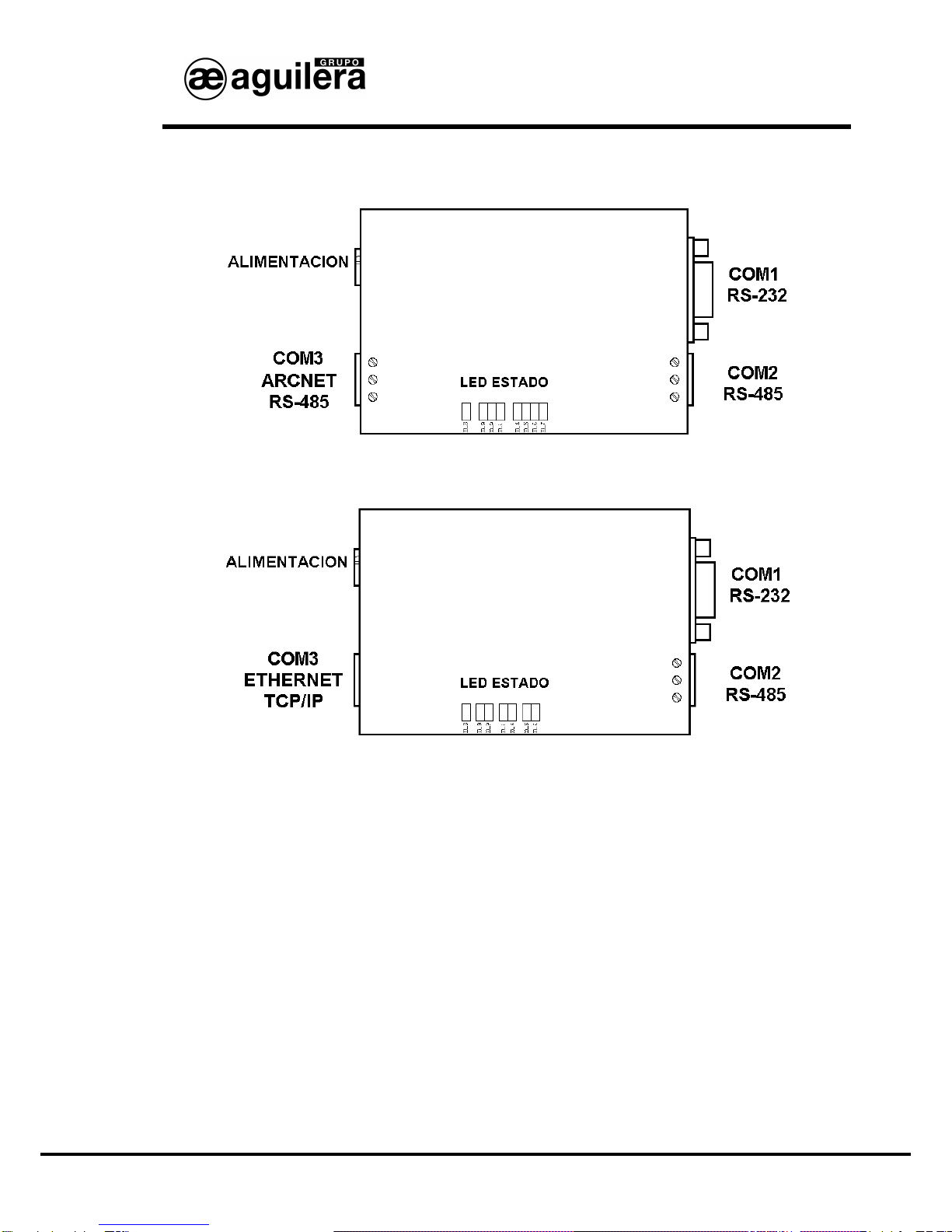
1CONNECTION SYSTEM AND STATUS LED...........................................................5
1.1 COM1 RS-232................................................................................................................5
1.2 COM2 RS-485................................................................................................................6
1.2.1 End of Line Resistors...............................................................................................................6
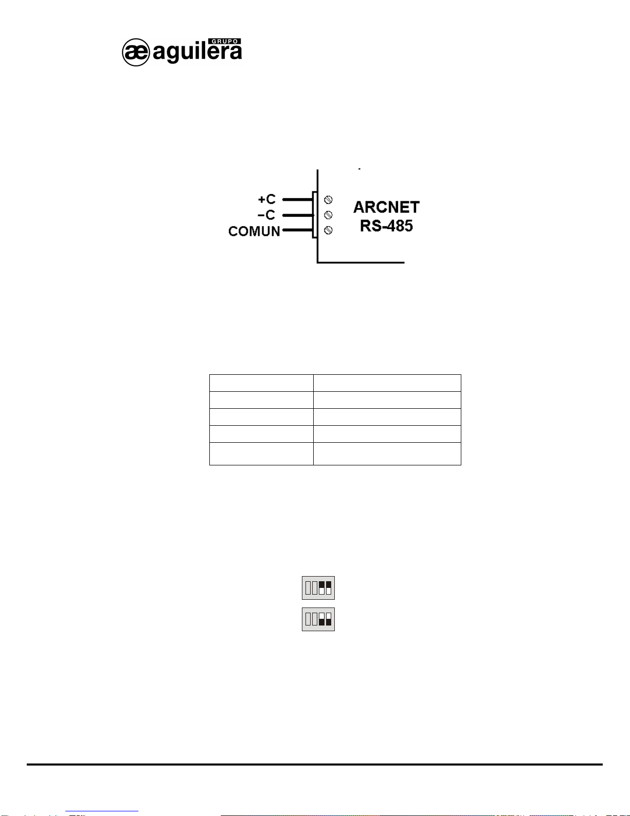
1.3 COM3 ARCNET RS-485................................................................................................7
1.3.1 End of Line Resistors...............................................................................................................7
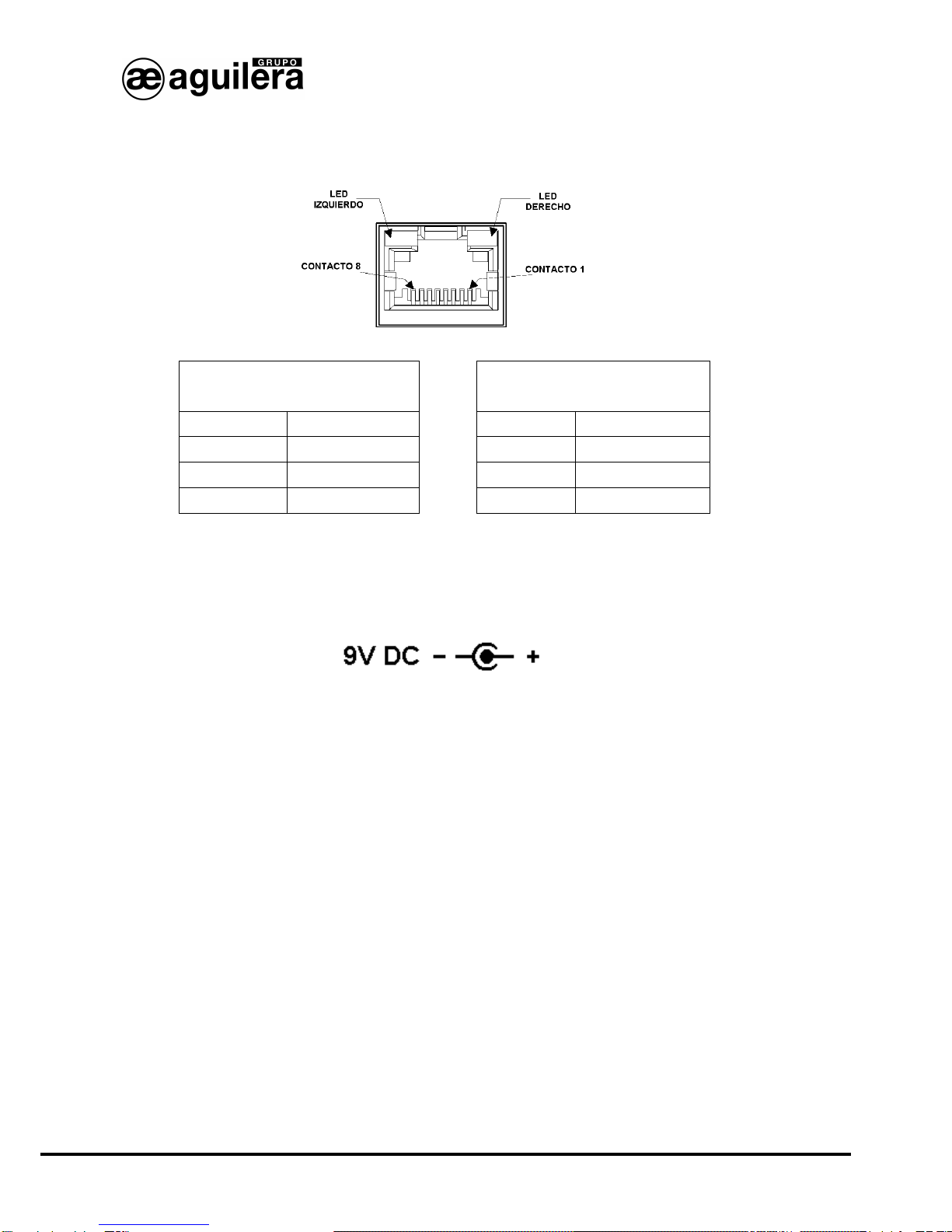
1.4 COM3 ETHERNET TCP/IP. ...........................................................................................8
1.5 POWER SUPPLY. .........................................................................................................8
2CUSTOMIZATION OF THE EQUIPMENT. ...............................................................9
2.1 PORT SELECTION. ............................................................................................................9
2.2 EQUIPMENT DETECTION..................................................................................................10
2.3 SELECTION OF THE WORK MODE.....................................................................................11
2.4 ORIGIN OF THE DATA.....................................................................................................12
2.5 COMMUNICATION SUPERVISION.......................................................................................13
2.6 CONFIGURATION OF THE WORK MODE.............................................................................14
2.6.1 Aguilera..................................................................................................................................14
2.6.2 MODBUS/RTU.......................................................................................................................15
2.6.3 MODBUS/TCP.......................................................................................................................16
2.6.4 N2 PROTOCOL.....................................................................................................................17
2.6.5 ESPA 4.4.4. ...........................................................................................................................18
2.6.6 Optimus. ................................................................................................................................19
2.6.7 Gateway.................................................................................................................................20
2.7 END OF THE PROCESS....................................................................................................21
3PARAMETER CONFIGURATION OF MODBUS PROTOCOL. ..............................23
3.1 DISCRETE INPUTS..........................................................................................................23
3.2 DISCRETE OUTPUTS.(COILS)..........................................................................................23
3.3 INPUT REGISTERS..........................................................................................................24
3.3.1 Limits. ....................................................................................................................................24
3.3.2 General: sectors. ...................................................................................................................24
3.3.3 General: zones. .....................................................................................................................25
3.3.4 System zone..........................................................................................................................26
3.3.5 Sector status..........................................................................................................................26
3.3.6 Zone status............................................................................................................................27
3.4 OUTPUT REGISTERS (HOLDING REGISTERS)...............................................................27
3.4.1 System clock..........................................................................................................................27
3.4.2 Resetting................................................................................................................................28
3.4.3 Sequences.............................................................................................................................28
3.5 ADDRESS MAP. ..............................................................................................................29
3.6 REPORTED STATUS. .......................................................................................................30
4PARAMETER CONFIGURATION OF ESPA 4.4.4 PROTOCOL.............................31
4.1 GENERAL....................................................................................................................31
4.1.1 Pager options.......................................................................... ¡Error! Marcador no definido.
4.1.2 Call end..................................................................................................................................31
4.2 ALARM. .......................................................................................................................32
4.2.1 Outputting messages.............................................................................................................32
4.3 PREALARM.................................................................................................................33
4.4 FAILURE......................................................................................................................34

Ae-man-817-0.0 v2.3 2AGUILERA ELECTRONICA
AE/SA-IDC AE/SA-GAT COMMUNICATION INTERFACE
5PARAMETER CONFIGURATION OF OPTIMUS PROTOCOL. ............................. 35
5.1 GENERAL PARAMETERS.................................................................................................35
5.2 PUBLIC ADDRESS GROUPS.............................................................................................35
5.3 ASSIGNMENT OF GROUPS TO ZONES...............................................................................36
6CONFIGURATION OF THE ETHERNET PORT....................................................39
6.1 CONFIGURATION OF THE MOXA MIINEPORT MICRO SERVER. ............................................40
6.1.1 Nport search Utility................................................................................................................40
6.1.2 Configuration of the Micro server..........................................................................................41
6.1.2.1 Network configuration. .....................................................................................................................42
6.1.2.2 Configuration of the serial port.........................................................................................................42
6.1.2.3 Operation modes. ............................................................................................................................44
6.1.2.3.1 TCP Server. ..............................................................................................................................44
6.1.2.3.2 TCP Client.................................................................................................................................46
6.1.2.4 Saving data and resetting. ...............................................................................................................47
6.2 CONFIGURATION OF THE LANTRONIX XPORT MICRO SERVER...........................................48
6.2.1 Device Installer...................................................................................................................... 48
6.2.2 Assignment of an IP address ...............................................................................................50
6.2.3 Configuration of the Micro server..........................................................................................52
6.2.3.1 Network configuration. .....................................................................................................................53
6.2.3.2 Configuration of the serial port.........................................................................................................54
6.2.3.3 Operation modes. ............................................................................................................................55
6.2.3.3.1 TCP Passive connection...........................................................................................................56
6.2.3.3.2 TCP Active connection..............................................................................................................58
6.2.3.4 Saving data and resetting. ...............................................................................................................59
7CONNECTION EXAMPLES......................... ¡ERROR! MARCADOR NO DEFINIDO.
7.1 AGUILERA ELECTRONICA AE2NET NETWORK.......................................................61
7.2 INTEGRATION WITH MODBUS OR N2 (METASYS)............................................................61

Ae-man-817-0.0 v2.3 3AGUILERA ELECTRONICA
AE/SA-IDC AE/SA-GAT COMMUNICATION INTERFACE
TECHNICAL DESCRIPTION.
AE/SA-IDC and AE/SA-GAT Communication Interface are multifunction and multiprotocol equipments that
can be customized to operate in different operation modes.
Designed by Aguilera Electrónica to allow the integration of the Algorithmic System equipments with
different communication protocols by other manufacturers.
It is provided with the following communication ports:
AE/SA-IDC AE/SA-GAT
COM1 RS-232 RS-232
COM2 RS-485 RS-485
COM3 ARCNET RS-485 ETHERNET TCP/IP
The equipment configuration is made through an external software and the configuration values are kept in
the EEPROM memory, which assures correct performance after a power supply failure.
Supported communication protocols to the present day are:
AE/SA-IDC AE/SA-GAT
Aguilera Electrónica ARCNET YES NO
MODBUS/RTU YES YES
MODBUS/TCP NO YES
N2 de METASYS YES YES
GATEWAY NO YES
ESPA 4.4.4 YES YES
OPTIMUS NO YES
This manual is valid for the version of firmware V3.0 or higher, but how to maintain the compatibility in
installations where equipments with firmware series 1 and 2 is also shown.

Ae-man-817-0.0 v2.3 4AGUILERA ELECTRONICA
AE/SA-IDC AE/SA-GAT COMMUNICATION INTERFACE

Ae-man-817-0.0 v2.3 5AGUILERA ELECTRONICA
AE/SA-IDC AE/SA-GAT COMMUNICATION INTERFACE
1CONNECTION SYSTEM AND STATUS LED.
AE/SA-IDC Communication Interface is equipped with the following connectors:
AE/SA-GAT is equipped with the following connectors:
1.1 COM1 RS-232.
It has a DB9 connector with the following pin assignment:
•Pin 2 TXD
•Pin 3 RXD
•Pin 5 GND
The connection to a RS-232 port of a PC is made through a direct serial cable as shown in the diagram
It has two status-indicator LEDs:
•Yellow reception.
•Red transmission.

Ae-man-817-0.0 v2.3 6AGUILERA ELECTRONICA
AE/SA-IDC AE/SA-GAT COMMUNICATION INTERFACE
1.2 COM2 RS-485.
It has connection terminals up to 4mm Ø, with the following assignment:
-Pin 1 +C
-Pin 2 -C
-Pin 3 Common
•It has two status-indicator LEDs LEDs:
•Yellow reception.
•Red transmission.
1.2.1 END OF LINE RESISTORS.
Through the selectors placed at the bottom of the equipment, an internal end of line resistor can be
enabled.
To enable it, selectors 1 and 2 of the back dilswitch1have to be ON.
ON
ON
1 2 3 4
1 2 3 4
TERMINACIÓN
SI
NO
1In model AE/SA-GAT, only selectors 1 and 2 are available.

Ae-man-817-0.0 v2.3 7AGUILERA ELECTRONICA
AE/SA-IDC AE/SA-GAT COMMUNICATION INTERFACE
1.3 COM3 ARCNET RS-485.
Only available in the model AE/SA-IDC, it has connection terminals up to 4 mmØ, with the following
assignment:
-Pin 1 +C
-Pin 2 -C
-Pin 3 Common
This port is exclusively to be used by Aguilera Electrónica protocol, for connections of AE2NET
networked equipments using an ARCNET network on RS-485.
It has three status-indicator LEDs:
•Yellow reception.
•Red transmission.
•Yellow failure (depending on the number of flashes).
Number of flashes Meaning
1 Wrong address
2 Error in hardware diagnostics
3 Duplicated network address
4
There are no more nodes in the
network
1.3.1 END OF LINE RESISTOR.
Through the selectors placed at the bottom of the equipment, a 120Ωinternal end of line resistor can be
enabled
To enable it, selectors 3 and 4 have to be ON.
ON
ON
1 2 3 4
1 2 3 4
TERMINACIÓN
SI
NO
The connexion should be carried out in a “Daisy chain” configuration and only the end of line resistors of
the equipments placed at the ends have to be enabled, whenever the impedance of the cable used is the
same value as the end of line resistor.

Ae-man-817-0.0 v2.3 8AGUILERA ELECTRONICA
AE/SA-IDC AE/SA-GAT COMMUNICATION INTERFACE
1.4 COM3 ETHERNET TCP/IP.
Only available in the model AE/SA-GAT, the connection is carried out through a 8-pin RJ-45 connector.
Left LED
Connection Right LED
Activity
Colour Meaning Colour Meaning
Off without connection Off Without activity
Orange 10 Mbps Orange Half Duplex
Green 100 Mbps Green Full Duplex
1.5 POWER SUPPLY.
The Communication Interface is fed through the connector, by means of a 9V DC/0.5A external feeder.
Polarity shown has to be observed.
There is a green indicator light showing that the equipment is fed and its performance is correct.
During the first five seconds, the indicator light flashes to show that it can be recognized by the
customizer, before starting the normal operation.

Ae-man-817-0.0 v2.3 9AGUILERA ELECTRONICA
AE/SA-IDC AE/SA-GAT COMMUNICATION INTERFACE
2CUSTOMIZATION OF THE EQUIPMENT.
Customization of the Communication Interface is carried out through the programme “Interface
Customizer”(AGE42IDC).
2.1 PORT SELECTION.
After running the application, the following window is shown where we will select the communication port
we are going to use for communication with the Communication Interface and then press the button
“Next”.
A communication port which is present in the PC should be selected, otherwise an error message will be
shown.
It also allows to select the language used for the programme operation.

Ae-man-817-0.0 v2.3 10 AGUILERA ELECTRONICA
AE/SA-IDC AE/SA-GAT COMMUNICATION INTERFACE
2.2 EQUIPMENT DETECTION.
In this step the programme tries to communicate with the AE/SA-IDC or AE/SA-GAT communication
Interface through the communication port selected in the previous step. Steps to be followed are shown
on the screen.
If communication is successful, the present equipment customization can be red to allow to be modified in
later steps.
Otherwise, the process can be repeated by pressing the button “Detect” or back to the previous step and
selecting another communication port if we have made a mistake.
NOTE:Unless the interface has not been customized, it is necessary to switch the equipment off and
then switch it on again. Press the button “Detect” before 5 seconds for the customizer to detect the
interface correctly. During these first 5 seconds, the interface remains in a special mode of configuration,
“listening” in its two ports the arrival of a customizer command. If no command arrives after some
seconds, the equipment will be reset automatically and starts to operate according to its customization.

Ae-man-817-0.0 v2.3 11 AGUILERA ELECTRONICA
AE/SA-IDC AE/SA-GAT COMMUNICATION INTERFACE
2.3 SELECTION OF THE WORK MODE.
In this step, the programme shows the currently configured work mode in the equipment, allowing us to
leave it or select another of the modes available.
Operation modes available change depending on the type of Communication Interface, AE/SA-IDC or
AE/SA-GAT.
Only operation modes available for the hardware detected are shown to be active.

Ae-man-817-0.0 v2.3 12 AGUILERA ELECTRONICA
AE/SA-IDC AE/SA-GAT COMMUNICATION INTERFACE
2.4 ORIGIN OF THE DATA.
The customizer programme allows us to choose the origin of the data to be used in order to carry out the
equipment customization.
•Editing a new customization initialized with default values, according to the work mode
selected.
•Editing the customization that the equipment is already provided with, maintaining the same
work mode but allowing some of the values to be modified.
•Obtaining a previously created customization from a file, that was saved for a later use or as
a back-up copy
•Use the classic customization for MODBUS,- COMPATIBILITY WITH VERSION 1.0 – Allows
the compatibility of equipments with firmware V2.0 or higher in installations where there are
equipments with firmware series 1. Same addresses base for the register sub-table are
automatically applied.
Only options adapting to the existing customization in the equipment and the work mode selected will be
available.

Ae-man-817-0.0 v2.3 13 AGUILERA ELECTRONICA
AE/SA-IDC AE/SA-GAT COMMUNICATION INTERFACE
2.5 COMMUNICATION SUPERVISION.
Algorithmic central units with firmware version v3.0 and higher are provided with a supervision device
allowing for failure signalization in the communications with third-party equipments.
As a general rule, enabling this option is recommendable as any failure in the communications between
the Interface and the integration equipment will be reported to the central unit to be properly signalized.
This option can only be enabled if the equipment is connected to a central unit with firmware version v3.0
or higher.

Ae-man-817-0.0 v2.3 14 AGUILERA ELECTRONICA
AE/SA-IDC AE/SA-GAT COMMUNICATION INTERFACE
2.6 CONFIGURATION OF THE WORK MODE.
Depending on the previously selected work mode, different operation windows will be displayed.
2.6.1 Aguilera.
This operation mode is only available in the model AE/SA-IDC.
Parameters necessary for the Aguilera work mode will be configured in this window.
-Address.It is the address the IDC will answer to in the network ARCNET. Range [1..31].
-ARCNET speed.Speed that communications by the port COM3 ARCNET RS-485 make. All
equipments that make up the ARCNET network should be configured at the same speed.
o39 Kbps
o78 Kbps
o156 Kbps
o312 Kbps
-COM1 (RS-232) Port. This port will be used for connecting to a PC through the AGE43 Control
Station software or AGE44 Remote Management of Installations through a RS-232 port. It should
be configured with the same parameters as the equipment to be connected.
oSpeed. (2400, 4800, 9600, 19200, 38400, 57600 bauds)
oParity.(None, Even, Odd)
oStop Bits. (1 bit, 2 bits)
-COM2 (RS-485) Port.This port will be used for connecting to a PC through the AGE43 Control
Station software or AGE44 Remote Management of Installations through a RS-485 port. It should
be configured with the same parameters as the equipment to be connected.
oSpeed. (2400, 4800, 9600, 19200, 38400, 57600 bauds)
oParity.(None, Even, Odd)
oStop Bits.(1 bit, 2 bits)

Ae-man-817-0.0 v2.3 15 AGUILERA ELECTRONICA
AE/SA-IDC AE/SA-GAT COMMUNICATION INTERFACE
2.6.2 MODBUS/RTU.
Parameters necessary for the Modbus/RTU work mode will be configured in this window.
-Address: It is the address the interface will answer to in the network Modbus. Range [1..255]
-COM1 (RS-232) Port.By default, this is the default port for the interface to communicate with the
central unit. It should be configured with the same parameters as the port of the central unit to be
connected.
oSpeed. (2400, 4800, 9600, 19200, 38400, 57600 bauds)
oParity.(None, Even, Odd)
oStop Bits.(1 bit, 2 bits)
-COM2 (RS-485) Port.It is the default port for the interface to communicate with the master
Modbus equipment. The configuration of this port should be the same as the other devices of the
Modbus network.
oSpeed. (2400, 4800, 9600, 19200, 38400, 57600 bauds)
oParity.(None, Even, Odd)
oStop Bits.(1 bit, 2 bits)
-Physical Interface. Optionally the use of both ports can be exchanged in such a way that
communications between master Modbus equipment and the interface are made via RS-232 and
communications between the interface and the central unit are RS-485. This option can be
selected by pressing the screen-printed key with two opposite arrows.
Once parameter selection has finished, the register configuration for MODBUS protocol is started, which
is described in section 3. Parameter configuration of MODBUS protocol

Ae-man-817-0.0 v2.3 16 AGUILERA ELECTRONICA
AE/SA-IDC AE/SA-GAT COMMUNICATION INTERFACE
2.6.3 MODBUS/TCP.
This operation mode is only available in the model AE/SA-GAT.
Parameters necessary for the Modbus/TCP work mode will be configured in this window.
-Address.It is the address the GAT will answer to in the network Modbus. Range [1..255]
-Port. This is the default port for the GAT to communicate with the central unit. It should be
configured in the same way and with the same parameters as the port of the central unit to be
connected.
oCOM1 (RS-232)
oCOM2 (RS-485).
-Speed.(2400, 4800, 9600, 19200, 38400, 57600 bauds)
-Parity.(None, Even, Odd)
-Stop Bits.(1 bit, 2 bits)
Once parameter selection has finished, the register configuration for MODBUS protocol is started, which
is described in section 3. Parameter configuration of MODBUS protocol
For the correct performance of the MODBUS/TCP mode, the Ethernet TCP/IP port should be configured.
This process is described in section 6 Configuration of the Ethernet port.The operation mode of the micro
server should be the appropriate one for this type of operation.

Ae-man-817-0.0 v2.3 17 AGUILERA ELECTRONICA
AE/SA-IDC AE/SA-GAT COMMUNICATION INTERFACE
2.6.4 N2 PROTOCOL.
Parameters necessary for the work mode of the N2 Protocol will be configured in this window.
-Address: It is the address the interface in the N2 network will answer to Range [1..255]
-Port COM1 (RS-232). This is the default port for the interface to communicate with the central
unit. It should be configured with the same parameters as the port of the central unit to be
connected.
oSpeed. (2400, 4800, 9600, 19200, 38400, 57600 bauds)
oParity.(None, Even, Odd)
oStop Bits.(1 bit, 2 bits)
-Port COM2 (RS-485). This is the default port for the interface to communicate with the
equipment with the N2 Protocol. Configuration of this port should be the same as other network
devices.
oSpeed. (2400, 4800, 9600, 19200, 38400, 57600 bauds)
oParity.(None, Even, Odd)
oStop Bits.(1 bit, 2 bits)
-Physical Interface. Optionally the use of both ports can be exchanged in such a way that
communications between equipment with N2 protocol and the interface are made via RS-232 and
communications between the interface and the central unit are RS-485. This option can be
selected by pressing the screen-printed key with two opposite arrows.

Ae-man-817-0.0 v2.3 18 AGUILERA ELECTRONICA
AE/SA-IDC AE/SA-GAT COMMUNICATION INTERFACE
2.6.5 ESPA 4.4.4.
Parameters necessary for the work mode of the ESPA 4.4.4 Protocol will be configured in this window.
-Port COM1 (RS-232). This is the default port for the interface to communicate with the central
unit. It should be configured with the same parameters as the port of the central unit to be
oSpeed. (2400, 4800, 9600, 19200, 38400, 57600 bauds)
oBits data. (7 bits, 8 bits)
oParity.(None, Even, Odd)
oStop Bits.(1 bit, 2 bits)
-Port COM2 (RS-485). This is the default port for the interface to communicate with the equipment
with ESPA 4.4.4 Protocol. Configuration of this port should be the same as the device to be
connected.
oSpeed. (2400, 4800, 9600, 19200, 38400, 57600 bauds)
oBits data. (7 bits, 8 bits)
oParity.(None, Even, Odd)
oStop Bits.(1 bit, 2 bits)
-Physical Interface. Optionally the use of both ports can be exchanged in such a way that
communications between equipment with ESPA 4.4.4 protocol and the interface are made via
RS-232 and communications between the interface and the central unit are RS-485. This option
can be selected by pressing the screen-printed key with two opposite arrows.
Once parameter selection has finished, the register configuration for the ESPA 4.4.4 protocol is started,
which is described in section 4. Parameter configuration of ESPA 4.4.4 protocol.
This manual suits for next models
1
Table of contents