manuals.online logo
Brands
  1. Home
  2. •
  3. Brands
  4. •
  5. Zennio
  6. •
  7. Recording Equipment
  8. •
  9. Zennio ZRX-KCI4SO User manual

Zennio ZRX-KCI4SO User manual

© Zennio Avance y Tecnología S.L. Edition 5 Futher information www.zennio.com Page 1/2
KCI
KNX Consumption Interface
ZRX-KCI4SO TECHNICAL DOCUMENTATION
FEATURES
•4 channels for consumption counters (meters) with S0-pulse outputs
(UNE-EN 62053-31) *.
•Registration of consumed electric power, cost and CO2 emissions that
can be split in up to 4 time intervals.
•Compliant with UNE-EN 62053-31 Class B.
•Total data saving on KNX bus power failure.
•KNX BCU integrated.
•Size 90 x 60 x 35 mm (2 DIN units).
•DIN rail unit assembly (EN 50022), with snap fit clamp.
•CE directives compliant (CE mark on the front side).
*Other counters (meters) with dry-voltage output or not complying S0 standard
may also work (previous test is recommended)
1. Battery holder
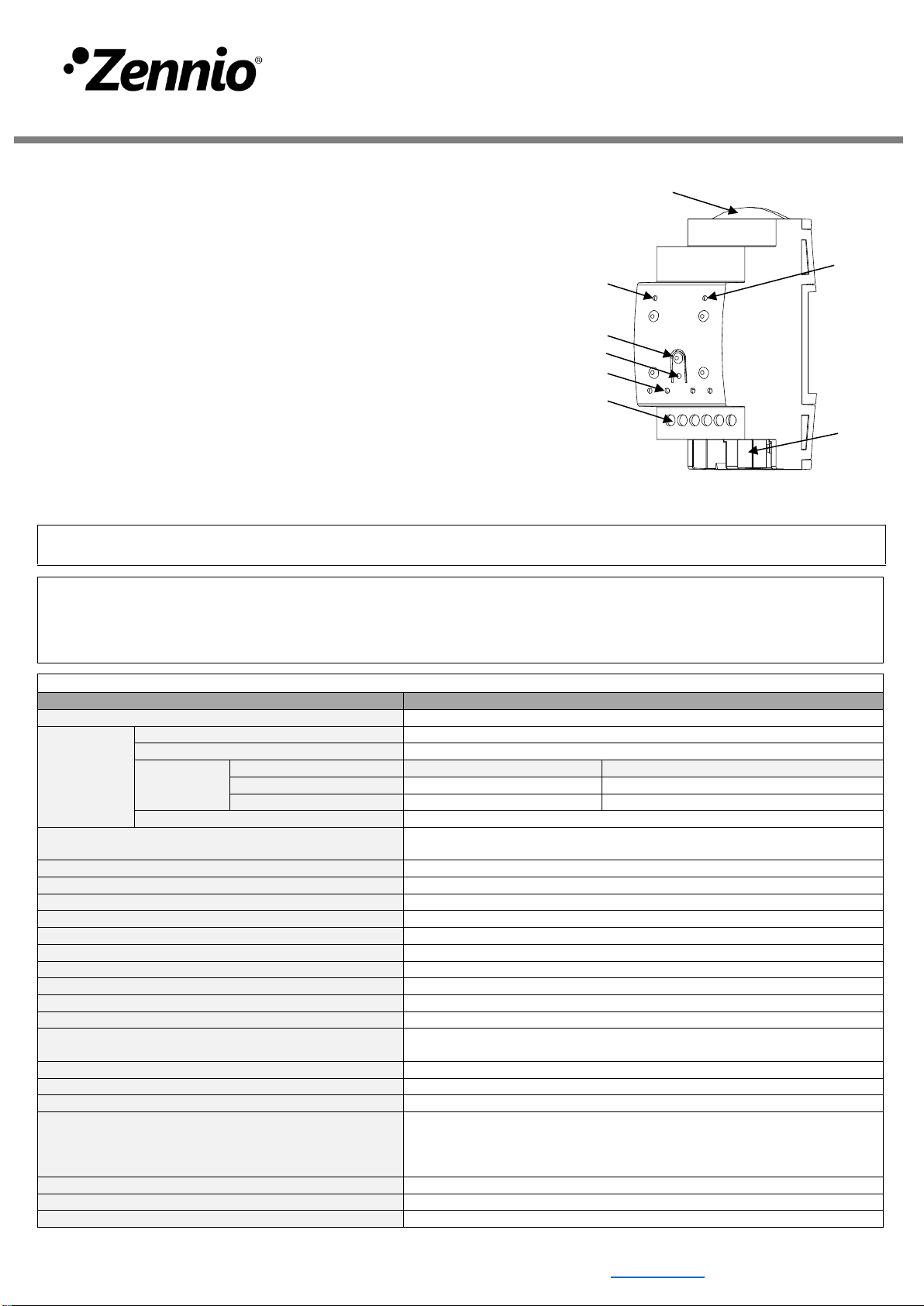
2. EMPTY batt. LED indicator
3. LOW batt. LED indicator
4. Programming button
5. Programming LED
6. Input Indicator LED
7. Input connectors
8. KNX connector
Figure 1: KCI
Programming button: short press to set programming mode. If this button is held while plugging the device into the KNX bus, it enters the safe mode.
Programming LED: programming mode indicator (red). When the device enters the safe mode, it blinks (red) every half second. During the start-up
(reset or after KNX bus failure) and if the device is not in safe mode, it emits a red flash.
LOW batt. LED: if this LED is blinking in red, replace the batteries as soon as possible.
EMPTY batt. LED: if this LED is blinking in red, the batteries are empty.
GENERAL SPECIFICATIONS
CONCEPT
DESCRIPTION
Type of device
Electric operation control device
KNX supply
Voltage (typical)
29VDC SELV
Voltage range
21..31VDC
Maximum
consumption
Voltage
mA
mW
29VDC (typical)
12.5
363
24VDC¹
15
360
Connection type
Typical TP1 bus connector for 0.80mm Ø rigid cable
External power supply
2 CR2032 battery (2 x 3V). It allows to keep counting pulses without the
KNX bus power supply
Operation temperature
0°C .. +55°C
Storage temperature
-20°C .. +55°C
Operation humidity
5 .. 95% (No condens.)
Storage humidity
5 .. 95% (No condens.)
Complementary characteristics
Class B
Protection class
III
Operation type
Continuous operation
Device action type
Type 1
Electrical stress period
Long
Degree of protection
IP20, clean environment
Installation
Independent device to be mounted inside electrical panels with DIN rail (EN
50022)
Minimum clearances
Not required
Response on KNX bus failure
Data saving according to parameterization
Response on KNX bus restart
Data recovery according to parameterization
Operation indicator
Programming LED indicates programming mode (red) or safe mode
(blinking red). LOW and EMPTY batt. LED indicate the battery level when
blinking in red (KNX supply necessary). LED input indicator blinks when a
pulse is received
Weight
89g (+ 6g bat.)
PCB CTI index
175V
Housing material
PC FR V0 halogen free
¹ Maximum consumption in the worst case scenario (KNX Fan-In model)
1
2
3
4
5
6
7
8
© Zennio Avance y Tecnología S.L. Edition 5 Futher information www.zennio.com Page 2/2
SAFETY INSTRUCTIONS
•Installation should only be performed by qualified professionals according to the laws and regulations applicable in each country.
•Do not connect the mains voltage nor any other external voltage to any point of the KNX bus; it would represent a risk for the entire
KNX system. The facility must have enough insulation between the mains (or auxiliary) voltage and the KNX bus or the wires of other
accessories, in case of being installed.
•Once the device is installed (in the panel or box), it must not be accessible from outside.
•Keep the device away from water and do not cover it with clothes, paper or any other material while in use.
•The WEEE logo means that this device contains electronic parts and it must be properly disposed of by following the instructions at
http://zennio.com/weee-regulation.
INPUTS SPECIFICATIONS AND CONNECTIONS
CONCEPT
DESCRIPTION
Number of S0 or dry
inputs
4
Inputs per common
2
Operation voltage
6VDC
Connection method
Screw terminal block
Cable cross-section
0.5-2.5mm² (IEC) / 26-12AWG (UL)
Maximum cable length
30m
Minimum pulse duration
30ms
WIRINGDIAGRAMS
Figure 2: Example of connections with SO pulse generators
Attaching KCI to DIN rail:
Removing KCI from DIN rail:
BATTERIES REPLACEMENT
1.
Extract the battery holder from the upper side of KCI. It is recommended to have the bus KNX connected during this
process to prevent S0 pulses loss.
2. Place the batteries in the battery holder (respecting the polarity shown) and insert it as indicated in the figure.
2
1
Figure 3: Mounting KCI on DIN rail

Other Zennio Recording Equipment manuals

Zennio KIPI User manual

Zennio

Zennio KIPI User manual

Zennio DALIBOX ZDI-DLB6 Guide

Zennio

Zennio DALIBOX ZDI-DLB6 Guide

Zennio KLIC-DD User manual

Zennio

Zennio KLIC-DD User manual

Zennio KLIC-DI SKY User manual

Zennio

Zennio KLIC-DI SKY User manual

Zennio BIN 44 User manual

Zennio

Zennio BIN 44 User manual

Zennio DALIBOX ZDI-DLB4 Guide

Zennio

Zennio DALIBOX ZDI-DLB4 Guide

Zennio KLIC-DI Quick start guide

Zennio

Zennio KLIC-DI Quick start guide

Zennio DALIBOX Interface 64/32 User manual

Zennio

Zennio DALIBOX Interface 64/32 User manual

Zennio ZRX-KCI4SO Guide

Zennio

Zennio ZRX-KCI4SO Guide

Zennio KNX USB SC User manual

Zennio

Zennio KNX USB SC User manual

Zennio DALIBOX ZDI-DLB4 Guide

Zennio

Zennio DALIBOX ZDI-DLB4 Guide

Zennio KNX ZRX-KCI4S0 Guide

Zennio

Zennio KNX ZRX-KCI4S0 Guide

Zennio ZDI-DLI User manual

Zennio

Zennio ZDI-DLI User manual

Zennio KLIC-DI User manual

Zennio

Zennio KLIC-DI User manual

Zennio ZDID64V3 User manual

Zennio

Zennio ZDID64V3 User manual

Zennio DALIBOX ZDI-DLB4 Guide

Zennio

Zennio DALIBOX ZDI-DLB4 Guide

Zennio KNX KCI 4 S0 User manual

Zennio

Zennio KNX KCI 4 S0 User manual

Zennio KNX ZRX-KCI4S0 Guide

Zennio

Zennio KNX ZRX-KCI4S0 Guide

Popular Recording Equipment manuals by other brands

Klein + Hummel K8-AI8 operating manual

Klein + Hummel

Klein + Hummel K8-AI8 operating manual

BSS Audio FDS-334T manual

BSS Audio

BSS Audio FDS-334T manual

Telos Alliance xNode Quick start installation guide

Telos Alliance

Telos Alliance xNode Quick start installation guide

Korg AmkII owner's manual

Korg

Korg AmkII owner's manual

midiphy LOOPA user manual

midiphy

midiphy LOOPA user manual

Cochlear Baha 5 Power user manual

Cochlear

Cochlear Baha 5 Power user manual

Akai MPC Renaissance quick start guide

Akai

Akai MPC Renaissance quick start guide

Solid State Logic SSL UC1 user guide

Solid State Logic

Solid State Logic SSL UC1 user guide

Elk ELK-M1XSLC instructions

Elk

Elk ELK-M1XSLC instructions

NewTek TriCaster 40 quick start guide

NewTek

NewTek TriCaster 40 quick start guide

Electro-Harmonix OCEANS 12 quick start guide

Electro-Harmonix

Electro-Harmonix OCEANS 12 quick start guide

Simplex 4100-1340 installation instructions

Simplex

Simplex 4100-1340 installation instructions

Tascam US-224 owner's manual

Tascam

Tascam US-224 owner's manual

Tegeler Raumzeitmaschine user manual

Tegeler

Tegeler Raumzeitmaschine user manual

SecEng SED-VTI Installation & user manual

SecEng

SecEng SED-VTI Installation & user manual

Neutron Sound Orgone Accumulator V3 Build guide

Neutron Sound

Neutron Sound Orgone Accumulator V3 Build guide

ETAS ES132.1 user guide

ETAS

ETAS ES132.1 user guide

SCIDYNE XIO-DI8 User's reference manual

SCIDYNE

SCIDYNE XIO-DI8 User's reference manual

manuals.online logo
manuals.online logoBrands
  • About & Mission
  • Contact us
  • Privacy Policy
  • Terms and Conditions

Copyright 2025 Manuals.Online. All Rights Reserved.