IXXAT tinCAN161 User manual

The expert for industrial and automotive communication
Hardware Manual
tinCAN161
Intelligent PC/CAN Interface

IXXAT
Headquarter US Sales Office
IXXAT Automation GmbH IXXAT Inc.
Leibnizstr. 15 120 Bedford Center Road
D-88250 Weingarten USA-Bedford, NH 03110
Tel.: +49 (0)7 51 / 5 61 46-0 Phone: +1-603-471-0800
Fax: +49 (0)7 51 / 5 61 46-29 Fax: +1-603-471-0880
Internet: www.ixxat.de Internet: www.ixxat.com
Support
In case of unsolvable problems with this product or other IXXAT products
please contact IXXAT in written form by:
Fax: +49 (0)7 51 / 5 61 46-29
Copyright
Duplication (copying, printing, microfilm or other forms) and the electronic
distribution of this document is only allowed with explicit permission of
IXXAT Automation GmbH. IXXAT Automation GmbH reserves the right to
change technical data without prior announcement. The general business
conditions and the regulations of the license agreement do apply. All rights
are reserved.
Document number: 4.01.0026.20000
Version: 1.4

Contents
1Introduction................................................................................5
1.1 Overview ............................................................................. 5
1.2 Performance features ......................................................... 5
1.3 Block diagram ..................................................................... 6
1.4 Support ............................................................................... 7
1.5 Returning hardware............................................................ 7
2Installation ..................................................................................8
2.1 Software installation .......................................................... 8
2.2 Hardware installation ......................................................... 8
3Configuration .............................................................................9
3.1 Memory range/Interrupt ..................................................... 9
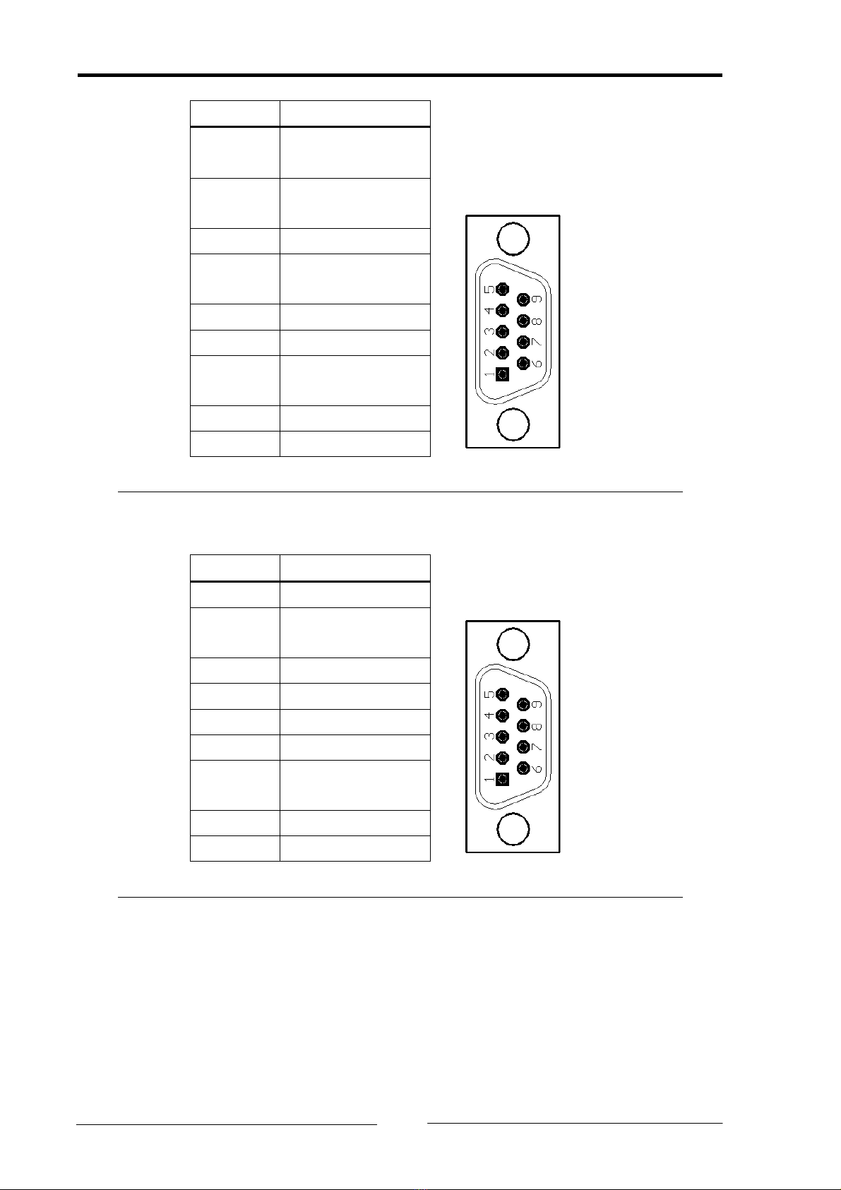
3.2 CAN bus interface ............................................................... 9
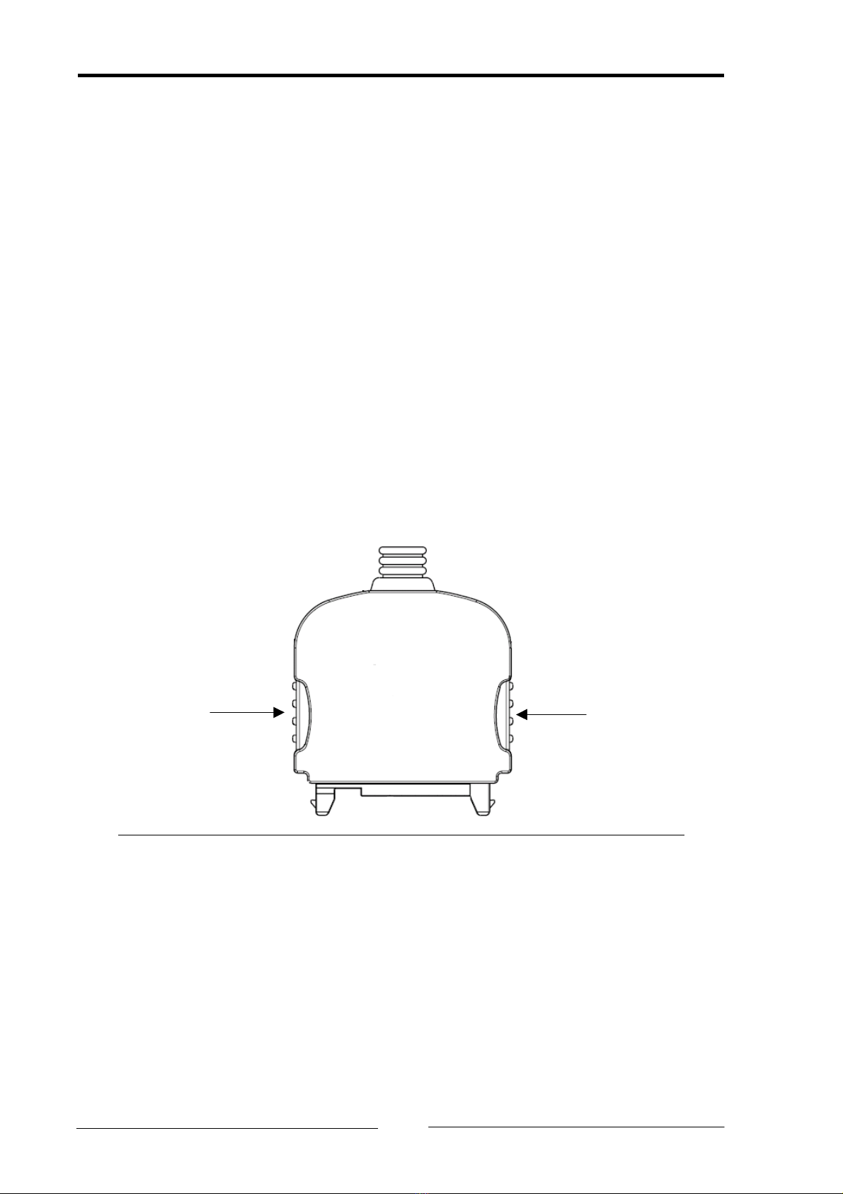
4Status LEDs ...............................................................................11
4.1 Bootloader ........................................................................ 11
4.2 Standard mode (with IXXAT VCI driver) ........................... 11
4.2.1 CAN1 / CAN2 LED...................................................................11
4.2.2 Low speed LED .......................................................................11
Appendix..........................................................................................12
Technical specifications............................................................ 12
EC declaration of conformity .................................................. 13
Copyright IXXAT Automation GmbH tinCAN161 - Manual, Version 1.4
3


Introduction
1 Introduction
1.1 Overview
Congratulations on your purchase of the IXXAT-PC-CAN interface tinCAN161, a
high-quality electronic component developed and manufactured according to the
latest technological standards.
This manual is intended to familiarize you with your interface, also referred to in
the following as tinCAN161. Please read this manual before beginning with the
installation.
1.2 Performance features
• Designed as PC-card type II (PCMCIA type II, 16 bit)
• Basic address plug & play via PC-card driver
• PC interrupts plug & play via PC-card driver
• Microcontroller Infineon C161, 25MHz
• Two CAN lines with Phillips SJA1000 controllers, 16 MHz
• 8 Kbyte Dual-Port-RAM, 8 semaphore register
• 16 bit memory mapped access (uses 16 Kbyte address space)
• “Hot-plug“ compatible (plug-in during operation of computer)
• Bus interface with two CAN channels in accordance with ISO/IS 11898-2 gal-
vanically isolated in external housing. CAN channel 1 can be switched to low
speed ISO11898-3 via software
Copyright IXXAT Automation GmbH tinCAN161 - Manual, Version 1.4
5

Introduction
1.3 Block diagram
PC-Card Slot
Interface logic
(DPRAM, Flags, CIS)
Microcontroller
Infineon C161
Flash
512KB
TxCAN1
RxCAN1
TxCAN2
RxCAN2
tinCAN161
15 pin plug
tinCAN161
bus interface
ISO11989-2/-3
RAM
1MB
1. CAN
controller
SJA1000
2. CAN
controller
SJA1000
VCC
GND
Port P3.4 (LED)
VCC
GND
CAN bus interface 1
Highspeed/Lowspeed
CAN bus interface 2
Highspeed
Fig. 1-1 Block diagram tinCAN161
Copyright IXXAT Automation GmbH tinCAN161 - Manual, Version 1.4
6

Introduction
1.4 Support
For more information on our products, FAQ lists and installation tips, please refer
to the support section of our website (http://www.ixxat.de), which also contains
information on current product versions and available updates.
If you have any further questions after studying the information on our website
and the manuals, please contact our support department. The support section on
our website contains the relevant forms for your support request. In order to fa-
cilitate our support work and enable a fast response, please provide precise in-
formation on the individual points and describe your question or problem in de-
tail.
If you would prefer to contact our support department by phone, please also
send a support request via our website first, so that our support department has
the relevant information available.
1.5 Returning hardware
If it is necessary to return hardware to us, please download the relevant RMA
form from our homepage and follow the instructions on this form. In the case of
repairs, please also describe the problem or fault in detail on the RMA form. This
will enable us to carry out the repair quickly.
Copyright IXXAT Automation GmbH tinCAN161 - Manual, Version 1.4
7

Installation
2 Installation
2.1 Software installation
A driver is required in order to operate the interface.
For the installation of the CAN driver VCI under Windows, please refer to the
VCI installation manual.
2.2 Hardware installation
Before you plug the tinCAN161 into the PCMCIA slot, install the software driver
(see Section 2.1).
Connect the tinCAN161 to the bus interface. For this the locking mechanism of
the plug of the bus interface must be pressed (see Fig. 2-1). The plug is protected
against polarity reversal, so that incorrect connection of the bus interface to the
microcontroller hardware is not possible.
press together
Fig. 2-1 Locking mechanism of the plug
Caution: Windows NT is not hot-plug-compatible. Under Windows NT the com-
puter must be switched off when you plug in the card.
Copyright IXXAT Automation GmbH tinCAN161 - Manual, Version 1.4
8

Configuration
3 Configuration
3.1 Memory range/Interrupt
The tinCAN161 is fully configured by the driver using the data in the Card Infor-
mation Structure (CIS). For operation with IXXAT software, no user interventions
are necessary.
3.2 CAN bus interface
The bus interface of the tinCAN161 is housed in a separate housing (see also
Fig. 1-1). The two CAN lines bus interfaces are galvanically isolated from each
other and from the PC. CAN line 1 can be switched between high speed (ISO
11898-2) and low speed (ISO 11898-3) via software. CAN line 2 has a high-speed
bus interface. The mechanical connection to the CAN bus is made in each case
with a 9-pin SUB-D connector. Pin allocation for high speed is in accordance with
CiA (CAN in Automation) DS-102, low speed (only CAN1) is connected to pin 1
and pin 4 (see Table 3-1 and Table 3-2).
Due to the galvanic isolation, the GND of CAN1 and CAN2 is isolated in each case
from the rest of the circuit.
The shielded connections of CAN1 and CAN2 are connected to the PC housing.
Copyright IXXAT Automation GmbH tinCAN161 - Manual, Version 1.4
9

Configuration
Pin no. Signal
1 CAN_L
(low speed)
2 CAN_L
(high speed)
3 GND
4 CAN_H
(low speed)
5 -
6 -
7 CAN_H
(high speed)
8 -
9 -
Table 3-1 Pin allocation of high / low speed bus interface (CAN1)
Pin no. Signal
1 -
2 CAN_L
(high speed)
3 GND
4 -
5 -
6 -
7 CAN_H
(high speed)
8 -
9 -
Table 3-2 Pin allocation of high-speed bus interface (CAN2)
Copyright IXXAT Automation GmbH tinCAN161 - Manual, Version 1.4
10

Status LEDs
4 Status LEDs
The tinCAN161 bus interface has three two-color status LEDs. Depending on the
operating mode of the tinCAN161, the LEDs behave as follows.
4.1 Bootloader
After plugging in the PCMCIA card, the bootloader of the tinCAN161 is active. In
this case the three LEDs flash green with a frequency of approx. 2 Hz.
4.2 Standard mode (with IXXAT VCI driver)
4.2.1 CAN1 / CAN2 LED
The LED CAN1 and CAN2 are lit green every time a message is received or trans-
mitted without errors. When the CAN error warning level is reached, the corre-
sponding LED is let red during reception or transmission. In the ’CAN BUS OFF’
state, communication is no longer possible and the LED is permanently lit red.
4.2.2 Low speed LED
The low speed LED is lit green when the low speed transceiver is activated on
CAN1. The LED switches to red when the low speed transceiver detects a bus er-
ror. Communication may still be possible if the automatic bus error management
can compensate for the bus error.
Copyright IXXAT Automation GmbH tinCAN161 - Manual, Version 1.4
11

Appendix
Appendix
Technical specifications
PC-card type: PCMCIA type II, 16-bit
Microcontroller: Infineon C161, 25MHz
RAM / Flash: 1 Mbyte / 512 Kbyte
Capacity: 20,000 CAN messages/s
CAN controller: 2x Phillips SJA1000, 16MHz
CAN transceiver: Texas Instruments SN65HVD251D or
Philips PCA82C251T
Max. number of CAN bus nodes: 120
Power supply: 5V DC ±5%
Power consumption typically 300 mA
Dimensions (L x B x H) in mm 89.5 x 54.0 x 4.5
Dimensions of bus interface in mm: 80 x 45 x 20
Weight incl. bus interface: approx. 130 g
Working temperature range 0 – 55 °C
Relative humidity 10-95%, non-condensing
Signal delay due to
galv. isolation typically 50 ns
EMC test in accordance with EN 55022:1998 + A1:2000 + A2:2003
EN 55024:1998 + A1:2000 + A2:2003
Protection type IP 40
Galv. isolation bus interface: 250 V AC between CAN1, CAN2 and PC
Notes on EMC
In order to comply with the EC directive on electro-magnetic compatibility, the
PCMCIA interface tinCAN161 may only be installed in a PC with a CE-symbol and
an RF-shielded housing. All leads connected to the interface must have a shielded
lead. The shield braiding must be connected to the connector housing using the
largest possible surface area.
Copyright IXXAT Automation GmbH tinCAN161 - Manual, Version 1.4
12

Appendix
Declaration of conformity
IXXAT Automation declares that the product: tinCAN161
Model: tinCAN161
with the article number: 1.01.0026.00020
complies with the EC-directive: 89/336/EEC
09.11.06, Dipl.-Ing. Christian Schlegel , Managing Director
IXXAT Automation GmbH
Leibnizstraße 15
88250 Weingarten
Copyright IXXAT Automation GmbH tinCAN161 - Manual, Version 1.4
13
Table of contents
Other IXXAT Recording Equipment manuals

IXXAT
IXXAT CAN@net II User manual

IXXAT
IXXAT iPC-I XC16/PCI User manual

IXXAT
IXXAT PC-I 03 User manual

IXXAT
IXXAT VCI User manual

IXXAT
IXXAT CANblue User manual

IXXAT
IXXAT iPC-I 165/PCI User manual

IXXAT
IXXAT iPC-I XC16/PCI User manual

IXXAT
IXXAT USB-to-CAN II User manual

IXXAT
IXXAT iPC-I 165 User manual

IXXAT
IXXAT iPC-I 320/PCI II User manual