AHL Solar Revolution User manual

Before assembling or turning on the motor please read and heed all
instructions.
• Be sure to have all necessary tools prior to beginning assembly.
• Please do not turn the motor on prior to installation. The unit is positioned at the factory to
enable accurate and proper installation. Turning the motor on before completing installa-
tion will disrupt the proper position for installation.
Tools required
2 (two) 7/16 inch wrenches
1 (one) 1/2 inch wrench
chain to hang lamps
tools and material to secure Solar RevolutionTM and to shelve the ballasts
SOLAR REVOLUTION™
The light mover for the next millennium
Congratulations! You have just purchased the most state of the art, high per-
formance, circular light mover ever offered to our industry–the SOLAR REVOLUTION™.
I embarked on the concept of the Solar Revolution™ over 2 years ago primarily out of
displeasure with what the industry had to offer. Customers kept asking me, “why can’t
somebody build a reliable circular mover that is extremely durable but also user friend-
ly?” At that moment the Solar Revolution™ was conceived. Now two years and several
designs later, the Solar Revolution™ has arrived.
Benefits of the Solar RevolutionTM
• heavy duty drive motor
• heavy duty microswitch rated to last for years
• heavy duty bearings and housing
• all-aluminum arms for strength and light weight
• whisper quiet operation and design
• extremely low profile, compact design provides maximum plant-to-light clearance
• no need to cut your lamp cords because no hard wiring is necessary
• extremely versatile–the unit can run one, two, or four lights with the same motor
• the Solar RevolutionTM runs 355 degrees in one direction then reverses and runs 355
degrees in the opposite direction, providing complete blending of metal halide and
high pressure sodium light
• light reflectors are easily adjusted both vertically and horizontally
• when used properly, the Solar RevolutionTM will dramatically increase garden efficiency
and plant performance
• 2 year warranty on workmanship, one year warranty on motor from the date of purchase

ASSEMBLY INSTRUCTIONS
1) Remove the Solar RevolutionTM from its box and visu-
ally inspect the unit for any damage.
2) The Solar RevolutionTM should include:
• 1 motor housing with two center bar assemblies attached
• 4 2 “ arm mounting bolts (already attached to center arm)
• 4 1/4” nuts for mounting bolts (already attached to center arm)
• 4 bolts to attach mounting plate to framing member in ceiling
• 2 aluminum extender arms
• 2 u-bracket assemblies to hang reflectors from the arms
• 8 zip ties
• Be sure that the Solar RevolutionTM is fastened to the framing members in the ceiling of
your greenhouse or grow room.
• If using multiple reflectors, please follow these directions:
• Each reflector with bulb should weigh about the same.
• If reflectors of different brands are used, the weight must be checked and
adjusted if necessary.
• If reflectors of the same brand are used, no adjustments are necessary.
• The reflectors should be the same distance from the center motor.
AHL has “ruler” tape attached to the arms to make this easier.
• If using multiple lamps do not exceed a combined total of 80 pounds.
• Make sure the the mounting surface is level.
• If using only one light, a counter-weight must be used.
• Make sure that the unit has enough circular clearance for the arm to rotate unobstructed.
If an arm gets impeded, damage may occur to the unit. Also make sure there are no wires
or cords hanging down that could impede the proper revolution of the motor.
WARNING:
If you only read one paragraph in these directions make it this one!

3) Note: one 1/2 inch wrench is necessary for
this step of installation. Using the four screws
provided attach the mounting plate SECURELY
to overhead framing members or other sturdy
wooden or metal structure.
4) There are two center bars: an upper and a lower.
The upper bar has yellow and pink stickers, the lower
has green and blue. Unscrew mounting nuts and
remove both mounting bolts from the upper bar. Slide
one extender arm into the bar with the yellow dot until
the holes in the bar and the arm align. Replace bolt,
and tighten nuts securely.
Repeat this step for the side of the center bar with the
pink dot .
5) AHL has included U-bracket hardware to hang your reflectors.
Take one of the brackets and place it onto one side arm.
Take the other and place it onto the other side. The U on
the U-bolt should be facing up, thus providing hanging
points at the base.
Note: there are 2 nuts per side for safety. One regular, one nyloc.
There is “ruler” tape on the arms to enable placing the lamps at
equal distances from the center motor. Position the brackets
where you want the lamp to hang and tighten the screws provid-
ed. Make sure that they are equally distant from the center.
upper center bar
extender arms
securely attached to
framing members!
NOTE:
It is important NOT to
move the arm in any way.
The arm should only move
via the motor.
O
securely
screwed to 2”X4”
lower center bar

6) Take one lamp cord and socket and drape it over the U-bracket on the extender arm on
the side of the center bar with the yellow dot. Make sure to leave enough slack in the cord
between the the socket and the U-bracket to enable hanging the reflector at its lowest point.
Zip tie the cord to the U-bracket hardware at the top of the arm.
7) Take the lamp cord and zip tie it to the YELLOW eye bolt
on the motor. The cord MUST pass on the side of the motor
with the GREEN eye bolt–not on the other side! Make sure
you leave enough slack in the lamp cord to accommodate
proper rotation of the light mover–about a 6” bow should be
sufficient.
yellow eye bolt
green eye
bolt
pink eye
bolt
bar with
the yel-
low dot
cord to
socket
allow enough
slack for
rotation (6”)
blue eye
bolt on
back side
lowest reach
of reflector

8) Take the second lamp cord and socket and drape it over the U-bracket on the extender
arm on the side of the center bar with the pink dot. Make sure to leave enough slack in the
cord between the the socket and the U-bracket to enable hanging the reflector at its lowest
point. Zip tie the cord to the U-bracket hardware at the top of the arm.
9) Take the lamp cord and zip tie it to the PINK eye bolt on the motor. The cord MUST pass
on the side of the motor with the BLUE eye bolt–not the other side! Make sure you leave
enough slack in the lamp cord to accommodate proper rotation of
the light mover–about a 6” bow should be sufficient.
10) Note: mounting chain (not included) is necessary for this step;
for optimum stability we recommend two chains per reflector.
Attach mounting chain onto each side of the U-bracket. Attach
both chains to the reflector and repeat for the other arm of the
mover.
A“third hand” (small, empty, sturdy box) may be
helpful to hang the reflectors since their weight
may over-tilt the arms, potentially damaging the
mover.
yellow
eye
bolt
green
eye bolt
pink eye
bolt
allow enough
slack for
rotation
bar with
the pink
dot
lamp cords and
power cord
going to ballasts
blue eye
bolt on
back side
weight
“third hand”
secured to ceiling

11) Attach the sockets
to each reflector with
the hardware provided
by the manufacturer.
Each lamp cord should
now come from a
reflector, up to and
attaching to the U-bolt
on the arm, past the
motor on its left side,
attaching to the eye bolt
on the opposite side,
and finally toward the
ballast.
12) Be sure that both lamp cords and the motor
cord are securely attached to the ceiling. It is
extremely important to make sure that the
arms can rotate without obstruction.
13) Ballast positioning: we recommend building
shelves to mount the ballasts at a height which allows
the cord to easily reach the reflectors. Remember that
most ballasts are heavy. The shelf needs to be well
built and attached to a wall stud or other sturdy struc-
ture.
Solar
Revolution
power cord and
lamp cords
ballast positioned on
secure shelf!

14) Finally, a note about the original position of the motor
assembly. When you purchased the Solar RevolutionTM it
came positioned from the factory ensuring these instruc-
tions are exact. Should the factory position be disrupted or
should you want to change the location of your mover, you
will have to reset the motor to its original position. When
you received your mover, the original position had the side
of the center bar with the yellow dot aligned with the pink
eye-bolt; the initial direction was counter-clockwise. To
return to these conditions turn on the motor and watch for
rotation in the clock-wise direction. When the yellow dot on
the center bar approaches the pink eye-bolt, the
microswitch that changes the direction of the motor will click and the motion will turn to
counter clock-wise. Immediately turn off the motor, and your mover will be ready to set up
according to these instructions.
yellow
dot
pink
eye
bolt
IMPORTANT ITEMS TO REMEMBER!
• Always use a counter weight if using just one reflector.
• When using two (2) reflectors, make sure they are positioned at equal distances from
the drive motor. Never have one reflector further in on one arm and further out on the
other!
• Always make sure that the reflector weights are the same. This only applies if different
brands of reflectors are being used.
• Make sure there is enough cord slack for the unit to rotate as described in step 9-10.
• If using chain and/or hooks make sure the “load” rating is adequate to handle the
weight.
• Make sure each ballast shelf is extremely secure.
• Make sure the Solar Revolution is mounted to the framing members in the ceiling of the
grow room or greenhouse.
• This unit is rated for a specified voltage identified by the label on the drive motor. Never
use this unit on a different voltage than specified.
• The unit is equipped with a 3 prong, grounded electrical plug. This unit will only fit into
a 3 prong outlet. Do not defeat the grounding connection. If unable to insert into wall out-
let, call an electrician to replace the outlet.
• Do not overload your household circuit. Two (2) 1000 watt lamps will consume 75-80%
of a standard house 20 amp breaker! The Solar RevolutionTM motor uses only 5.5 watts.
• Always unplug the unit if you are adjusting Grow Light height.
• The electrical portion of the unit is not serviceable. Do not attempt to open the unit
under any circumstances–this will void the warranty! If the unit fails or malfunctions, call
AHL Garden Supply at 505-255-3677 for further instructions.

Four reflectors
Four reflector
cord configuration
additional extender arms
for four lamps
original
extender arms
additional cords must
pass over upper
(original) extender
arms

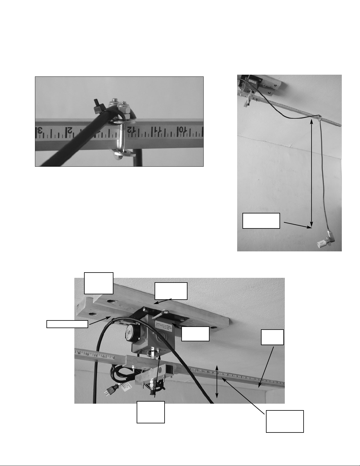
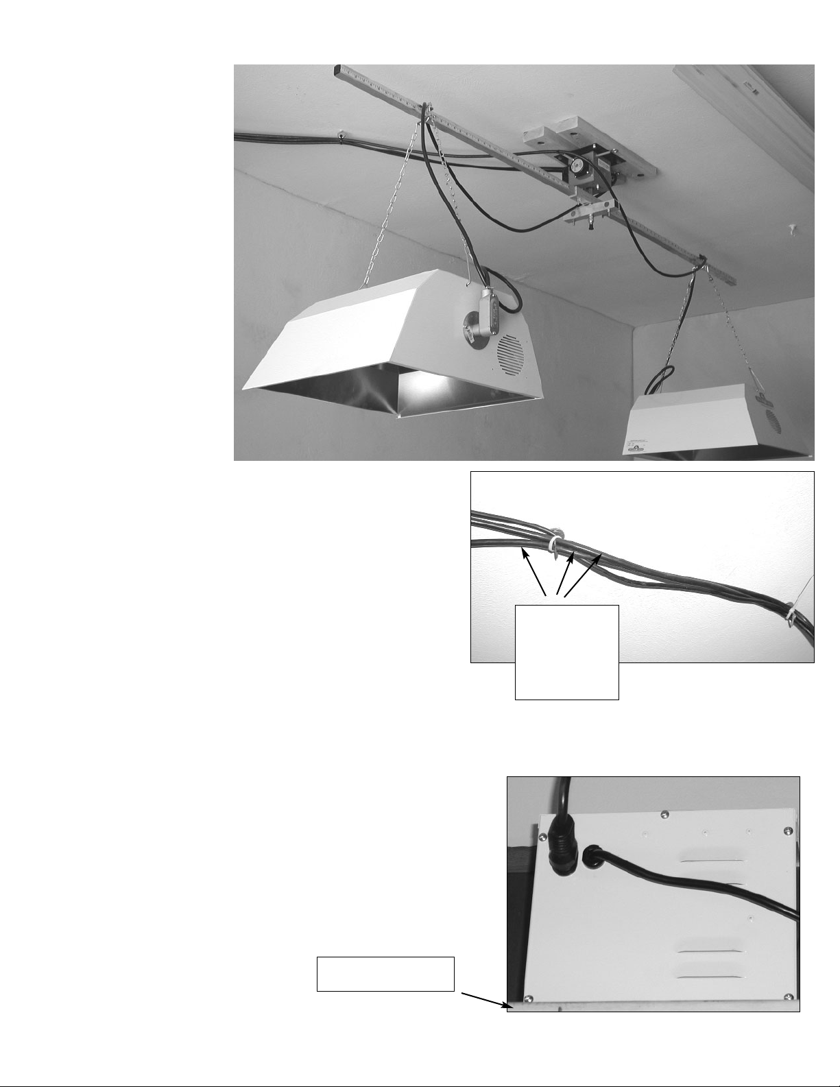
The photos on the previous page show the socket cord configuration for four reflectors.
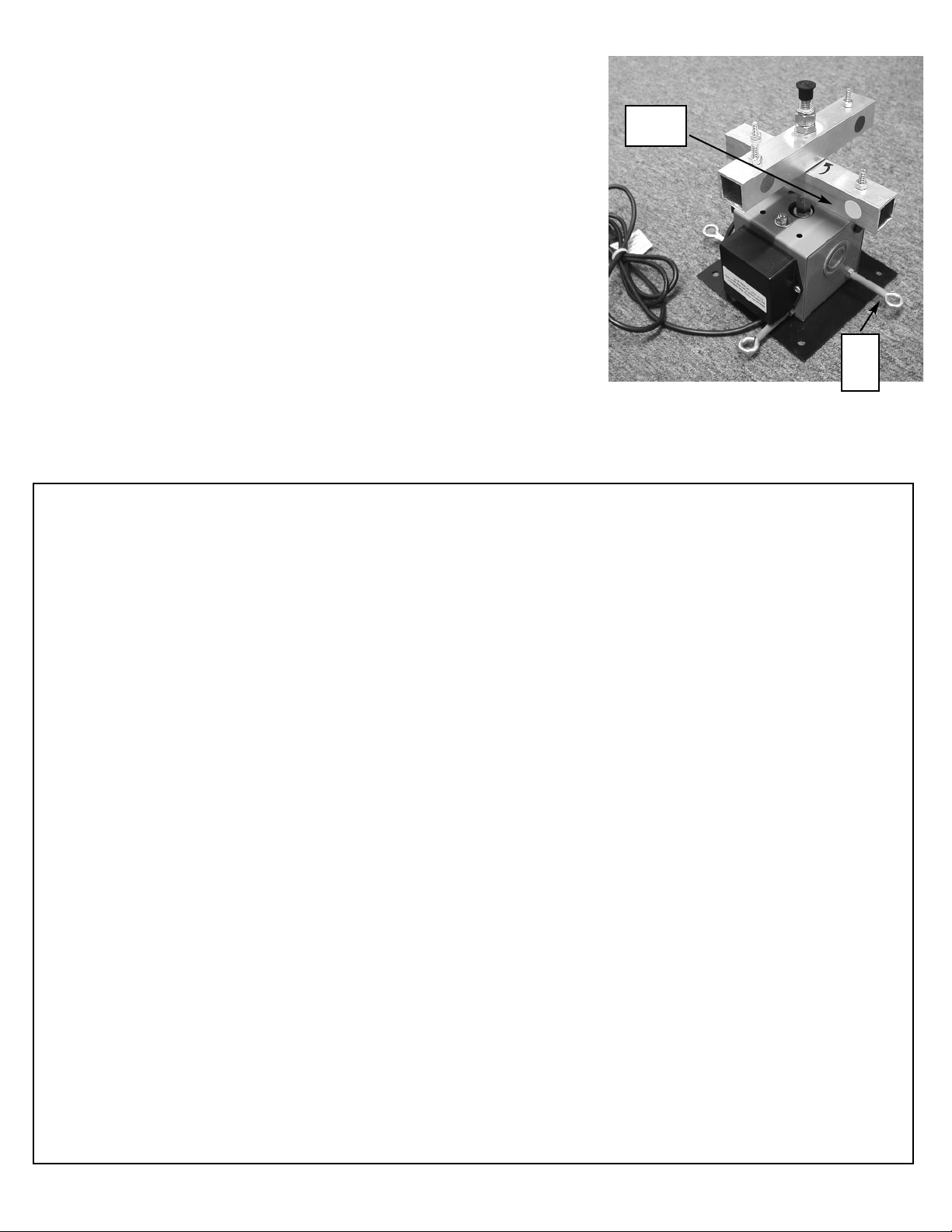
Two additional extender arms will slide into the lower center bar-the one with the blue and
green dots. The cord from the reflector on the side of the center bar with the blue dot ought
to attach to the U-bracket, go over the extender arm perpendicular while passing on the
side of the motor with the yellow eye bolt, and attach to the blue eye bolt. The cord from
the reflector on the side of the center bar with the green dot ought to attach to the U-brack-
et, go over the extender arm perpendicular while passing on the side of the motor with the
pink eye bolt, and attach to the green eye bolt. The same principle applies for each exten-
der arm. The cord comes up from the socket, attaches securely to the U-bracket assembly,
passes on the left of the motor, and attaches securely to the eyebolt opposite, leaving about
six inches hanging slack. Also, it is very important when using four extender arms that the
cord goes OVER the extender arm situated cross-wise to the original.
LIMITED WARRANTY
AHL inc. (company) warrants to the original purchaser that said product (Solar Revolution TM) will be free
rom defect in workmanship and materials for a period of two (2) years, one (1) year on all motors from the
date of purchase. If there is a perceived problem with the Solar Revolution, contact AHL inc. (505)-255-
3677 with a description of the problem. If necessary, AHL will issue a warranty return authorization num-
ber. Once received, AHL inc. will inspect the unit and repair or replace any defective part. AHL inc.
eserves the right to refuse warranty service if the unit has been opened, misused, damage or modified in
any way. If sending the unit, customer is responsible for initial postage, and AHL inc. will cover the postage
back within the continental United States. Under no circumstance will AHL inc. accept warranty work with-
out the return authorization number printed on the OUTSIDE of the box! If there is a failure, please contact
AHL inc. prior to sending.
Limitations:
mplied warranties, including those of fitness for a particular purpose and merchantability (an unwritten war-
anty that the product is fit for ordinary use), are limited to Two (2) years from the date of purchase on
workmanship and materials, one (1) year on the drive motor. We will not pay for loss of time, inconve-
nience, loss of use of your Solar Revolution TM or property damage caused by your Solar RevolutionTM or
ts failure to work, or any other incidental or consequential damages.
Some states do not allow limitations on how long an implied warranty lasts or the exclusion or limitation of
ncidental or consequential damages, so the above exclusion or limitations may not apply to you.
AHL
Albuquerque Hydroponics & Lighting
1051 San Mateo Blvd SE
Albuquerque,NM 87108
phone 505.255.3677
fax 505.255.7417
email [email protected]
Table of contents
Popular Light Fixture manuals by other brands

Core Lighting
Core Lighting ColourPoint Mini quick start guide

HUBBELL LIGHTING
HUBBELL LIGHTING DUAL LITE DYN Series Installation, operation and service instructions

WESTEK
WESTEK NEONW4M quick start guide

Philips
Philips 6911232PH Instruction leaflet

Lightolier
Lightolier Calculite CS8142 specification

Heitronic
Heitronic 38166 installation instructions

Home Accents Holiday
Home Accents Holiday TY232-2014-1 Assembly instructions

RSA Lighting
RSA Lighting Combolight LV Series LV240MH Specifications

for Living
for Living 25050 operating instructions

HOLOPHANE
HOLOPHANE Illuminaire installation instructions

LUG
LUG HI-BAY installation instructions

Lightolier
Lightolier Calculite C6P30A specification