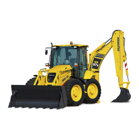
ahlmann AS 65 User manual

BETRIEBS-
ANLEITUNG
SCHWENK-
LADER
Ahlmann Baumaschinen GmbH D-24782 Büdelsdorf
Telefon 04331/351-325 ·Teletex (17) 433 111 ·Telefax 04331/351404
BETRIEBS-
ANLEITUNG
SCHWENK-
LADER
Ahlmann Baumaschinen GmbH D-24782 Büdelsdorf
Telefon 04331/351-325 ·Teletex (17) 433 111 ·Telefax 04331/351404
MANUEL DE
L'OPERATEUR
CHARGEUSE
PIVOTANTE
MANUEL DE
L'OPERATEUR
CHARGEUSE
PIVOTANTE
OPERATING
INSTRUCTIONS
SWING SHOVEL
LOADER
OPERATING
INSTRUCTIONS
SWING SHOVEL
LOADER
1002879A 1002879A
AS 65 AS 85 AS 65 AS 85

I S05D/S06DI S05D/S06D
Einführung
Vorwort
Ahlmann Schwenklader, Knicklader
und Frontlader sind Erzeugnisse aus
der umfangreichen Produktpalette
der Ahlmann Baumaschinen für
breitgestreute, verschiedenartige
Einsätze.
Jahrzehntelange Erfahrungen beim
Bau von Erdbewegungsmaschinen
und umfangreichen Zusatzprogrammen,
moderne Konstruktions- und Ferti-
gungsverfahren, sorgfältige Erprobung
und höchste Qualitätsanforderungen
garantieren die Zuverlässigkeit Ihres
Ahlmann Radladers.
Umfang der von dem Hersteller mit-
gelieferten Dokumentation:
- Betriebsanleitung Gerät
- Betriebsanleitung Motor
- Ersatzteilliste Gerät
- Ersatzteilliste Motor
- EG-Konformitätserklärung
Betriebsanleitung
Die Betriebsanleitung enthält An-
gaben, die der Betreiber zur sach-
gemäßen Bedienung und Wartung
benötigt.

S05D/S06DS05D/S06D I I
Introduction
Préface
Les chargeuses pivotantes, les
chargeuses articulées et les
chargeuses frontales de la vaste
gamme de production de Ahlmann
Baumaschinen, sont des machi-
nes destinées à des utilisations
très diverses.
Une expérience de plusieurs dé-
cennies dans la construction
d’engins de terrassement et
d’équipements complémentaires,
des procédés modernes de con-
ception et de fabrication, des es-
sais méticuleux et des exigences
de qualité très strictes garantissent
la fiabilité de votre chargeuse sur
pneus Ahlmann.
La documentation constructeur
fournie comprend:
- Manuel de l’opérateur pour la
machine
- Manuel de l’opérateur pour le
moteur
- Liste des pièces de rechange
pour la machine
- Liste des pièces de rechange
pour le moteur
- Déclaration de conformité CE
Manuel de l’opérateur
Le manuel de l’opérateur contient
toutes les informations nécessaires
à l’opérateur pour une utilisation
et un entretien appropriés de la
machine.
Introduction
Preface
Ahlmann’s swivel shovel loader,
articulated loader and loader exca-
vator with backhoe are machines
included in Ahlmann’s vast product
range covering a wide variety of
working tasks.
Decades of experience in the con-
struction of earthmoving machines,
the wide range of attachments
available as well as modern produc-
tion facilities, careful testing and
highest quality demand guarantee
the highest degree of reliability of
your Ahlmann machine.
Theextentofdocumentationdelivered
by the manufacturer includes the
following:
- Equipment operating instructions
- Engine operating instructions
- Equipment spare parts list
- EC conformity declaration
Operationinstructions
The operation instruction contains
all the information which the user
requires for operation and mainte-
nance.

S05D/S06D S05D/S06D
II
Im Abschnitt "Wartung" sind alle
Wartungsarbeiten und Funktions-
prüfungen beschrieben, die von ein-
gewiesenem Personal durchgeführt
werden müssen.
Nicht beschrieben sind größere
Instandsetzungen, welche nur vom
Hersteller autorisierten und geschul-
ten Personal durchgeführt werden
dürfen. Hierzu gehören insbeson-
dere Anlagen, die der StVZO und
der UVV unterliegen.
Durch Konstruktionsänderungen,
die sich der Hersteller vorbehält,
kann es zu abweichender bildlicher
Darstellung kommen, die aber auf
den sachlichen Inhalt keinen Ein-
fluß hat.
Handhabung dieser
Betriebsanleitung
Begriffserläuterungen
- Die Bezeichnung "links" bzw.
"rechts" ist für das Grundgerät
vom Fahrerstand aus in Fahrt-
richtung zu sehen.
- Sonderausstattung
bedeutet: Wird nicht serienmäßig
eingebaut
Bildhinweise
- (3-35)
bedeutet: Kapitel 3, Bild 35
- (3-35/1)
bedeutet: Kapitel 3, Bild 35,
Position 1
- (3-35/Pfeil)
bedeutet: Kapitel 3, Bild 35,

S05D/S06DS05D/S06D II II
Dans le chapitre „entretien“, vous
trouverez la description de tous les
travaux d’entretien et de contrôles
de fonction pouvant être faits par
des spécialistes formés à cet effet.
Les travaux de réparations plus
importants n’y figurent pas, du fait
qu’ils ne peuvent être réalisés que
par des spécialistes compétents ou
du personnel autorisé ou formé par
le fabricant. Ceci est surtout le cas
pour des véhicules étant soumis
aux prescriptions de l’arrêté ministé-
riel pour véhicules routiers (Code
de la Route et Instructions pour la
Prévention des Accidents).
Sous réserve de modifications de
construction de la part du fabricant,
il est possible que les représenta-
tions graphiques ne correspondent
pas tout à fait au véhicule fourni
mais cela n’a aucune importance
pratique.
Indications pratiques pour se
servir du manuel de service
Explication des termes
- L’indication „gauche“, resp.
„droite“ valent pour l’équipement
de base à partir de la position du
conducteur dans le sens de
marche.
- Installations optionnelles
signifie que ces installations ne
sont pas montées en série.
Légende pour les figures
- (3-35)
signifie: chapitre 3, figure 35
- (3-35/1)
signifie: chapitre 3, figure 35,
position 1
- (3-35/flèche)
signifie: chapitre 3, figure 35,
In the “Maintenance” section, all
maintenance work and operation
tests are described which can be
carried out by trained personnel.
Repairs on a larger scale which may
only be carried out by specialized
personnel or by personnel authori-
zed and trained by the manufacturer,
in particular those units subject to
the Motor Vehicle Construction and
Use Regulations and the Regula-
tions for the Prevention of Accidents,
are not described.
Due to the construction modifica-
tions reserved by the manufacturer,
there may be differences in the
figures; however, this has no
influence on the technical contents.
How to handle this manual
Explanations
- The designation “left” and “right”
is to be seen from the driver’s seat
in driving direction.
- Optional equipment means: not
fitted in series.
Information about illustrations
- (3-35)
means: chapter 3, fig. 35
- (3-35/1)
means: chapter 3, fig. 35, item 1
- (3-35/arrow)
means: chapter 3, fig. 35,

S05D/S06D S05D/S06D
III
Verwendete Abkürzungen
UVV = Unfallverhütungsvor-
schrift
StVZO = Straßenverkehrszulas-
sungsordnung
Ausgabe: 09.1997
Druck: 04.2002
III
Verwendete Abkürzungen
UVV = Unfallverhütungsvor-
schrift
StVZO = Straßenverkehrszulas-
sungsordnung
Ausgabe: 09.1997
Druck: 04.2002

S05D/S06DS05D/S06D III III
Abréviations
UVV = Unfallverhütungsvorschrift
(Règlement de Prévoyance
contre les Accidents)
StVZO= Straßenverkehrszulas-
sungsordnung (prescrip-
tions de l’arrêté ministériel
en vue des véhicules
routiers)
Edition 09.97
Abréviations
UVV = Unfallverhütungsvorschrift
(Règlement de Prévoyance
contre les Accidents)
StVZO= Straßenverkehrszulas-
sungsordnung (prescrip-
tions de l’arrêté ministériel
en vue des véhicules
routiers)
Edition 09.97
Abbreviations used:
UVV =
Unfallverhütungsvorschrift
(Accident Prevention
Regulations)
StVZO = Straßenverkehrzulas-
sungsordnung (German
Traffic Regulations)
Edition: 09.97
Abbreviations used:
UVV =
Unfallverhütungsvorschrift
(Accident Prevention
Regulations)
StVZO = Straßenverkehrzulas-
sungsordnung (German
Traffic Regulations)
Edition: 09.97

S05D/S06DS05D/S06D V
Inhaltsverzeichnis
1 Grundlegende Sicherheitshinweise 1 - 1
1.1 Warnhinweise und Symbole 1 - 1
1.2 Bestimmungsgemäße Verwendung 1 - 1
1.3 Organisatorische Maßnahmen 1 - 2
1.4 Personalauswahl und -qualifikation 1 - 4
1.5 Sicherheitshinweise zu bestimmten Betriebsphasen 1 - 5
1.5.1 Normalbetrieb 1 - 5
1.5.2 Sonderarbeiten im Rahmen der Nutzung des Gerätes
und Störungsbeseitigung im Arbeitsablauf; Entsorgung 1 - 10
1.6 Hinweise auf besondere Gefahrenarten 1 - 14
1.6.1 Elektrische Energie 1 - 14
1.6.2 Hydraulik 1 - 16
1.6.3 Lärm 1 - 16
1.6.4 Öle, Fette und andere chemische Substanzen 1 - 17
1.6.5 Gas, Staub, Dampf, Rauch 1 - 17
1.7 Transport und Abschleppen; Wiederinbetriebnahme 1 - 18
1.8 Sicherheitshinweise für den Unternehmer
oder sein weisungsbefugtes Personal 1 - 19
1.8.1 Organisatorische Maßnahmen 1 - 19
1.8.2 Personalauswahl und -qualifikation;
grundsätzliche Pflichten 1 - 19
2 Beschilderung 2 - 1
2.1 Warn- und Hinweisschilder 2 - 1
2.2 Sicherungen 2 - 2
2.3 Symbolschilder 2 - 3
3 Technische Daten 3 - 1
3.1.1 Gerät 3 - 1
3.1.2 Motor 3 - 1
3.1.3 Anlasser 3 - 1
3.1.4 Drehstromgenerator 3 - 1
3.1.5 Hydrostatischer Fahrantrieb 3 - 2
3.1.6 Achslasten 3 - 2
3.1.7 Reifen 3 - 2
3.1.8 Lenkanlage 3 - 2
3.1.9 Bremsanlage 3 - 3
3.1.10 Elektrische Anlage 3 - 3
D
V
D
Inhaltsverzeichnis
1 Grundlegende Sicherheitshinweise 1 - 1
1.1 Warnhinweise und Symbole 1 - 1
1.2 Bestimmungsgemäße Verwendung 1 - 1
1.3 Organisatorische Maßnahmen 1 - 2
1.4 Personalauswahl und -qualifikation 1 - 4
1.5 Sicherheitshinweise zu bestimmten Betriebsphasen 1 - 5
1.5.1 Normalbetrieb 1 - 5
1.5.2 Sonderarbeiten im Rahmen der Nutzung des Gerätes
und Störungsbeseitigung im Arbeitsablauf; Entsorgung 1 - 10
1.6 Hinweise auf besondere Gefahrenarten 1 - 14
1.6.1 Elektrische Energie 1 - 14
1.6.2 Hydraulik 1 - 16
1.6.3 Lärm 1 - 16
1.6.4 Öle, Fette und andere chemische Substanzen 1 - 17
1.6.5 Gas, Staub, Dampf, Rauch 1 - 17
1.7 Transport und Abschleppen; Wiederinbetriebnahme 1 - 18
1.8 Sicherheitshinweise für den Unternehmer
oder sein weisungsbefugtes Personal 1 - 19
1.8.1 Organisatorische Maßnahmen 1 - 19
1.8.2 Personalauswahl und -qualifikation;
grundsätzliche Pflichten 1 - 19
2 Beschilderung 2 - 1
2.1 Warn- und Hinweisschilder 2 - 1
2.2 Sicherungen 2 - 2
2.3 Symbolschilder 2 - 3
3 Technische Daten 3 - 1
3.1.1 Gerät 3 - 1
3.1.2 Motor 3 - 1
3.1.3 Anlasser 3 - 1
3.1.4 Drehstromgenerator 3 - 1
3.1.5 Hydrostatischer Fahrantrieb 3 - 2
3.1.6 Achslasten 3 - 2
3.1.7 Reifen 3 - 2
3.1.8 Lenkanlage 3 - 2
3.1.9 Bremsanlage 3 - 3
3.1.10 Elektrische Anlage 3 - 3
3.1 AS 65 3 - 1 3.1 AS 65 3 - 1

S05D/S06D S05D/S06D
VI
D
VI
D
3.1.11 Hydraulikanlage 3 - 3
3.1.11.1 Schwenkwerk 3 - 3
3.1.11.2 Abstützanlage 3 - 3
3.1.12 Kraftstoffversorgungsanlage 3 - 4
3.1.13 Heizungs- und Belüftungsanlage 3 - 4
3.1.14 Vollstrom-Saugfilterung 3 - 4
3.1.15 Elektrische Verschmutzungsanzeige 3 - 4
3.1.16 Ölkühler mit temperaturgeregeltem Lüfter 3 - 4
3.2.1 Gerät 3 - 5
3.2.2 Motor 3 - 5
3.2.3 Anlasser 3 - 5
3.2.4 Drehstromgenerator 3 - 5
3.2.5 Hydrostatischer Fahrantrieb 3 - 6
3.2.6 Achslasten 3 - 6
3.2.7 Reifen 3 - 6
3.2.8 Lenkanlage 3 - 6
3.2.9 Bremsanlage 3 - 7
3.2.10 Elektrische Anlage 3 - 7
3.2.11 Hydraulikanlage 3 - 7
3.2.11.1 Schwenkwerk 3 - 7
3.2.11.2 Abstützanlage 3 - 7
3.2.12 Kraftstoffversorgungsanlage 3 - 8
3.2.13 Heizungs- und Belüftungsanlage 3 - 8
3.2.14 Vollstrom-Saugfilterung 3 - 8
3.2.15 Elektrische Verschmutzungsanzeige 3 - 8
3.2.16 Ölkühler mit temperaturgeregeltem Lüfter 3 - 8
3.3.1 Schaufeln 3 - 9
3.3.2 Staplervorsatz 3 - 10
3.3.3 Frontbagger 3 - 11
3.3.4 Greifer 3 - 12
3.3.5 Lasthaken 3 - 13
3.4.1 Schaufeln 3 - 14
3.4.2 Staplervorsatz 3 - 15
3.4.3 Frontbagger 3 - 16
3.4.4 Greifer 3 - 17
3.4.5 Lasthaken 3 - 18
4 Beschreibung 4 - 1
4.1 Übersicht 4 - 1
4.2 Gerät 4 - 2
3.3 Anbaugeräte AS 65 3 - 9
3.4 Anbaugeräte AS 85/AZ 85 3 - 14
3.2 AS 85/AZ 85 3 - 5 3.2 AS 85/AZ 85 3 - 5
3.3 Anbaugeräte AS 65 3 - 9
3.4 Anbaugeräte AS 85/AZ 85 3 - 14

S05D/S06DS05D/S06D VII
D
VII
D
4.3 Radwechsel 4 - 8
4.4 Bedienelemente 4 - 11
4.5 Armaturenkasten 4 - 12
5 Bedienung 5 - 1
5.1 Prüfungen vor Inbetriebnahme 5 - 1
5.2 Inbetriebnahme 5 - 1
5.2.1 Dieselmotor anlassen 5 - 1
5.2.2 Winterbetrieb 5 - 2
5.2.2.1 Kraftstoff 5 - 2
5.2.2.2 Motorölwechsel 5 - 3
5.2.2.3 Ölwechsel Hydraulikanlage 5 - 3
5.2.2.4 Frostschutz für Scheibenwaschanlage 5 - 4
5.2.3 Fahren mit dem Gerät auf öffentlichen Straßen 5 - 4
5.2.3.1 Mitführen einer Schaufel 5 - 5
5.2.3.2 Mitführen einer Schaufel mit Frontbagger 5 - 6
5.2.4 Arbeiten mit dem Gerät 5 - 8
5.2.5 Heizungs- und Belüftungsanlage 5 - 11
5.2.5.1 Luftmenge einstellen 5 - 11
5.2.5.2 Heizung einschalten 5 - 11
5.3 Außerbetriebsetzen 5 - 12
5.3.1 Gerät abstellen 5 - 12
5.3.2 Dieselmotor abstellen 5 - 12
5.3.3 Heizungs- und Belüftungsanlage ausschalten 5 - 13
5.3.4 Gerät verlassen 5 - 13
5.4 Fahrersitz einstellen 5 - 13
5.5 Lenkung umschalten 5 - 14
6 Anbaugeräte 6 - 1
6.1 An- und Abbau von Anbaugeräten
ohne hydraulischen Anschluß 6 - 1
6.1.1 Standard-/Leichtgutschaufel 6 - 1
6.1.2 Staplervorsatz 6 - 2
6.1.3 Lasthaken 6 - 2
6.2 An- und Abbau von Anbaugeräten
mit hydraulischem Anschluß 6 - 3
6.2.1 Mehrzweckschaufel 6 - 3
6.2.2 Frontbagger 6 - 6
6.2.2.1 Löffelwechsel 6 - 7
6.2.3 Greifer 6 - 7
6.3 Verwendung weiterer Anbaugeräte 6 - 9
7 Bergen, Abschleppen, Verzurren, Kranverlasten 7 - 1
7.1 Bergen, Abschleppen, Verzurren 7 - 1

S05D/S06D S05D/S06D
7.1.1 Bergen/Abschleppen des Schwenkladers bei
ausgefallenem Motor oder ausgefallenem Fahrantrieb 7 - 1
7.1.1.1 Abschleppen des Schwenkladers
bei ausgefallenem Motor 7 - 1
7.1.1.2 Abschleppen des Schwenkladers
bei ausgefallenem Fahrantrieb 7 - 4
7.2 Kranverlasten 7 - 7
8 Wartung 8 - 1
8.1 Wartungshinweise 8 - 1
8.2 Wartungsarbeiten 8 - 2
8.2.1 Ölstandskontrolle Motor 8 - 2
8.2.2 Ölstandskontrolle Achsen 8 - 2
8.2.2.1 Hinterachse Langsamläufer » 20 km/h « 8 - 2
8.2.2.2 Hinterachse Schnelläufer » 30 km/h « 8 - 3
8.2.2.3 Planetengetriebe 8 - 3
8.2.2.4 Vorderachse 8 - 3
8.2.3 Ölstandskontrolle Hydraulikölbehälter 8 - 4
8.2.4 Ölwechsel Motor 8 - 4
8.2.5 Ölwechsel Achsen 8 - 4
8.2.5.1 Hinterachse Langsamläufer » 20 km/h « 8 - 4
8.2.5.2 Hinterachse Schnelläufer » 30 km/h « 8 - 5
8.2.5.3 Planetengetriebe 8 - 6
8.2.5.4 Vorderachse 8 - 7
8.2.6 Ölwechsel Hydraulikanlage 8 - 7
8.2.7 Hydraulikölfilter-Einsätze wechseln 8 - 8
8.2.8 Luftfilter warten/wechseln 8 - 9
8.2.9 Sicherheitspatrone wechseln 8 - 11
8.2.10 Kraftstoffilter wechseln 8 - 12
8.2.11 Starterbatterie wechseln 8 - 12
8.2.12 Frischluftfilter warten/wechseln 8 - 13
8.2.13 Betriebsbremse prüfen/einstellen 8 - 13
8.2.14 Feststellbremse prüfen/einstellen 8 - 15
8.3 Fettschmierstellen/Ölschmierstellen 8 - 16
8.4 Wartungsplan 8 - 21
9 Störung, Ursache und Abhilfe 9 - 1
10 Anhang
10.1 Elektro-Schaltplan
10.2 Hydraulik-Schaltplan
10.3 Muster “Prüfhinweise für Schaufellader”
D
VIII
D
VIII
7.1.1 Bergen/Abschleppen des Schwenkladers bei
ausgefallenem Motor oder ausgefallenem Fahrantrieb 7 - 1
7.1.1.1 Abschleppen des Schwenkladers
bei ausgefallenem Motor 7 - 1
7.1.1.2 Abschleppen des Schwenkladers
bei ausgefallenem Fahrantrieb 7 - 4
7.2 Kranverlasten 7 - 7
8 Wartung 8 - 1
8.1 Wartungshinweise 8 - 1
8.2 Wartungsarbeiten 8 - 2
8.2.1 Ölstandskontrolle Motor 8 - 2
8.2.2 Ölstandskontrolle Achsen 8 - 2
8.2.2.1 Hinterachse Langsamläufer » 20 km/h « 8 - 2
8.2.2.2 Hinterachse Schnelläufer » 30 km/h « 8 - 3
8.2.2.3 Planetengetriebe 8 - 3
8.2.2.4 Vorderachse 8 - 3
8.2.3 Ölstandskontrolle Hydraulikölbehälter 8 - 4
8.2.4 Ölwechsel Motor 8 - 4
8.2.5 Ölwechsel Achsen 8 - 4
8.2.5.1 Hinterachse Langsamläufer » 20 km/h « 8 - 4
8.2.5.2 Hinterachse Schnelläufer » 30 km/h « 8 - 5
8.2.5.3 Planetengetriebe 8 - 6
8.2.5.4 Vorderachse 8 - 7
8.2.6 Ölwechsel Hydraulikanlage 8 - 7
8.2.7 Hydraulikölfilter-Einsätze wechseln 8 - 8
8.2.8 Luftfilter warten/wechseln 8 - 9
8.2.9 Sicherheitspatrone wechseln 8 - 11
8.2.10 Kraftstoffilter wechseln 8 - 12
8.2.11 Starterbatterie wechseln 8 - 12
8.2.12 Frischluftfilter warten/wechseln 8 - 13
8.2.13 Betriebsbremse prüfen/einstellen 8 - 13
8.2.14 Feststellbremse prüfen/einstellen 8 - 15
8.3 Fettschmierstellen/Ölschmierstellen 8 - 16
8.4 Wartungsplan 8 - 21
9 Störung, Ursache und Abhilfe 9 - 1
10 Anhang
10.1 Elektro-Schaltplan
10.2 Hydraulik-Schaltplan
10.3 Muster “Prüfhinweise für Schaufellader”

S05D/S06DS05D/S06D VV
FF
Table des matières
1 Consignes de sécurité fondamentales 1 - 1
1.1 Signaux d’attention et symboles 1 - 1
1.2 Utilisation conforme à l'emploi prévu 1 - 1
1.3 Mesures d’organisation 1 - 2
1.4 Choix du personnel et qualification 1 - 4
1.5 Consignes de sécurité pour des phases
de fonctionnement déterminées 1 - 5
1.5.1 Service normal 1 - 5
1.5.2 Travaux particuliers dans le cadre de l’exploitation de
la machine et de travaux d’entretien et de dépannage
pendant le travail; Evacuation 1 - 10
1.6 Instructions concernant des catégories de dangers
particuliers 1 - 14
1.6.1 Energie électrique 1 - 14
1.6.2 Hydraulique 1 - 16
1.6.3 Bruit 1 - 16
1.6.4 Huile, graisses et autres substances chimiques 1 - 17
1.6.5 Gaz, poussière, vapeur, fumée 1 - 17
1.7 Transport et remorquage; remise en service 1 - 18
1.8 Consignes de sécurité pour l’entrepreneur ou son
personnel autorisé à donner des instructions 1 - 19
1.8.1 Mesures d’organisation 1 - 19
1.8.2 Choix du personnel et qualification;
obligations fondamentales 1 - 19
2 Signalisation 2 - 1
2.1 Signaux de danger et d´indication 2 - 1
2.2 Protections 2 - 2
2.3 Panneaux de symboles 2 - 3
3 Caractéristiques techniques 3 - 1
3.1.1 Machine 3 - 1
3.1.2 Moteur 3 - 1
3.1.3 Démarreur 3 - 1
3.1.4 Alternateur triphasé 3 - 1
3.1.5 Organe de translation hydrostatique 3 - 2
3.1.6 Charges par essieu 3 - 2
3.1.7 Pneus 3 - 2
3.1.8 Système de direction 3 - 2
3.1.9 Système de freinage 3 - 3
3.1.10 Installation électrique 3 - 3
3.1 AS 65 3 - 1 3.1 AS 65 3 - 1

S05D/S06D S05D/S06D
VI VI
F F
3.1.11 Equipement hydraulique 3 - 3
3.1.11.1 Système de pivotement 3 - 3
3.1.11.2 Equipement de support 3 - 3
3.1.12 Système d´alimentation en combustible 3 - 4
3.1.13 Système de chauffage et d´aération 3 - 4
3.1.14 Filtrage à aspiration 3 - 4
3.1.15 Indicateur électrique d´encrassement 3 - 4
3.1.16 Réfrigérant d´huileavec réglage par thermostat 3 - 4
3.2.1 Machine 3 - 5
3.2.2 Moteur 3 - 5
3.2.3 Démarreur 3 - 5
3.2.4 Alternateur triphasé 3 - 5
3.2.5 Organe de translation hydrostatique 3 - 6
3.2.6 Charges par essieu 3 - 6
3.2.7 Pneus 3 - 6
3.2.8 Système de direction 3 - 6
3.2.9 Système de freinage 3 - 7
3.2.10 Installation électrique 3 - 7
3.2.11 Equipement hydraulique 3 - 7
3.2.11.1 Système de pivotement 3 - 7
3.2.11.2 Equipement de support 3 - 7
3.2.12 Système d´alimentation en combustible 3 - 8
3.2.13 Installation de chauffage et d´aération 3 - 8
3.2.14 Filtrage à aspiration 3 - 8
3.2.15 Indicateur électrique d´encrassement 3 - 8
3.2.16
Réfrigérant d´huile par ventilateur réglé par température
3- 8
3.3.1 Godets 3 - 9
3.3.2 Palettiseur 3 - 10
3.3.3 Pelle frontale 3 - 11
3.3.4 Benne-preneuse 3 - 12
3.3.5 Crochets de grue 3 - 13
3.4.1 Godets 3 - 14
3.4.2 Palettiseur 3 - 15
3.4.3 Pelle frontale 3 - 16
3.4.4 Benne-preneuse 3 - 17
3.4.5 Crochets de grue 3 - 18
4 Description 4 - 1
4.1 Vue d´ensemble 4 - 1
4.2 Machine 4 - 2
3.2 AS 85/AZ 85 3 - 1
3.3 Equipements complémentaires AS 65 3 - 9
3.4 Equipements complémentaires AS 85/AZ 85 3 - 14 3.4 Equipements complémentaires AS 85/AZ 85 3 - 14
3.3 Equipements complémentaires AS 65 3 - 9
3.2 AS 85/AZ 85 3 - 1

S05D/S06DS05D/S06D VIIVII
FF
4.3 Changement de roue 4 - 8
4.4 Organes de commande 4 - 11
4.5 Tableau de bord 4 - 12
5 Conduite du véhicule 5 - 1
5.1 Contrôle avant la mise en service 5 - 1
5.2 Mise en marche 5 - 1
5.2.1 Lancement du moteur diesel 5 - 1
5.2.2 Fonctionnement hivernal 5 - 2
5.2.2.1 Carburant 5 - 2
5.2.2.2 Vidange de l´huile moteur 5 - 3
5.2.2.3 Vidange de l´installation hydraulique 5 - 3
5.2.2.4 Antigel pour le lave-glace 5 - 4
5.2.3 Conduite avec le véhicule sur voies publiques 5 - 4
5.2.3.1 Machine équipée d´un godet 5 - 5
5.2.3.2 Machine équipée d´un godet avec pelle frontale 5 - 6
5.2.4 Travailler avec la machine 5 - 8
5.2.5 Système de chauffage et d´aération 5 - 11
5.2.5.1 Réglage du volume d´air 5 - 11
5.2.5.2 Mettre le chauffage 5 - 11
5.3 Arrêt de l´utilisation de la machine 5 - 12
5.3.1 Rangement de la machine 5 - 12
5.3.2 Arrêter le moteur diesel 5 - 12
5.3.3 Arrêt du chauffage et du système d´aération 5 - 13
5.3.4 Quitter le véhicule 5 - 13
5.4 Réglage du siège du conducteur 5 - 13
5.5 Inversion de la direction 5 - 14
6 Equipements complémentaires 6 - 1
6.1 Montage et démontage d´équipements
complémentaires sans branchement hydraulique 6 - 1
6.1.1 Godet standard/godet pour matériaux légers 6 - 1
6.1.2 Palettiseur 6 - 2
6.1.3 Crochet de grue 6 - 2
6.2 Montage et démontage d´équipements
complémentaires avec branchement hydraulique 6 - 3
6.2.1 Godet multi-fonctions 6 - 3
6.2.2 Pelle frontale 6 - 6
6.2.2.1 Changement de pelle 6 - 7
6.2.3 Benne-preneuse 6 - 7
6.3 Utilisation d´autres équipements complémentaires 6 - 9
7 Dépannage, remorquage, amarrage, grutage 7 - 1
7.1 Dépannage, remorquage, amarrage 7 - 1

S05D/S06D S05D/S06D
VIII VIII
F F
7.1.1 Dépannage/remorquage d´une chargeuse pivotante
en panne de moteur ou de dispositif de translation 7 - 1
7.1.1.1
Remorquage d´une chargeuse pivotante en panne de moteur
7- 1
7.1.1.2 Remorquage d´une chargeuse pivotante en panne
de dispositif de translation 7 - 4
7.2 Grutage 7 - 7
8 Entretien 8 - 1
8.1 Instructions pour l´ entretien 8 - 1
8.2 Travaux d´entretien 8 - 2
8.2.1 Contrôle du niveau d´huile moteur 8 - 2
8.2.2 Contrôle du niveau d´huile des essieux 8 - 2
8.2.2.1 Essieu AR véhicules à vitesse lente » 20 km/h « 8 - 2
8.2.2.2 Essieu AR véhicules à vitesse élevée » 30 km/h « 8 - 3
8.2.2.3 Engrenage planétaire 8 - 3
8.2.2.4 Essieu AV 8 - 3
8.2.3 Contrôle du niveau d´ huile du réservoir hydraulique 8 - 4
8.2.4 Vidange moteur 8 - 4
8.2.5 Vidange essieux 8 - 4
8.2.5.1 Essieu AR véhicules à vitesse lente » 20 km/h « 8 - 4
8.2.5.2 Essieu AR véhicules à vitesse élevée » 30 km/h « 8 - 5
8.2.5.3 Engrenage planétaire 8 - 6
8.2.5.4 Essieu AV 8 - 7
8.2.6 Vidange de l´équipement hydraulique 8 - 7
8.2.7 Remplacer la cartouche du filtre à huile hydraulique 8 - 8
8.2.8 Entretien/remplacement du filtre à air 8 - 9
8.2.9 Remplacer la cartouche de sécurité 8 - 11
8.2.10 Remplacer le filtre du carburant 8 - 12
8.2.11 Remplacer la batterie du démarreur 8 - 12
8.2.12 Entretien/remplacement du filtre d´air frais 8 - 13
8.2.13 Contrôler/régler le frein de service 8 - 13
8.2.14 Contrôler/régler le frein de parking 8 - 15
8.3 Points de graissage/Points d´huilage 8 - 16
8.4 Tableau d´entretien 8 - 21
9 Dérangements, causes et remèdes 9 - 1
10
Appendice
10.1 Schéma électrique
10.2 Schéma hydraulique
10.3 Echantillon “Remarques sur le contrôle pour chargeuse”

S05D/S06DS05D/S06D VV
GB
Table of contents
1 Fundamental safety instructions 1 - 1
1.1 Warnings and symbols 1 - 1
1.2 Use of the loader as authorized 1 - 1
1.3 Organizational measures 1 - 2
1.4 Selection of personnel and necessary qualification 1 - 4
1.5 Safety information for certain operating phases 1 - 5
1.5.1 Normal operation 1 - 5
1.5.2 Special work within the exploitation of the machine
and elimination of defects during process of work; disposal 1 - 10
1.6 Instructions regarding special categories 1 - 14
1.6.1 Electrical energy 1 - 14
1.6.2 Hydraulic systems 1 - 16
1.6.3 Noise 1 - 16
1.6.4 Oil, grease and other chemical substances 1 - 17
1.6.5 Gas, dust, steam, smoke 1 - 17
1.7 Transport and towing; restart 1 - 18
1.8 Safety information for the contractor or the
contractor’s authorized personnel 1 - 19
1.8.1 Organizational measures 1 - 19
1.8.2 Selection of personnel and necessary qualification;
additional duties 1 - 19
2 Signs 2 - 1
2.1 Warning and information signs 2 - 1
2.2 Fuses 2 - 2
2.3 Symbols 2 - 3
3 Technical Data 3 - 1
3.1.1 Loader 3 - 1
3.1.2 Engine 3 - 1
3.1.3 Starter 3 - 1
3.1.4 Alternator 3 - 1
3.1.5 Hydrostatic drive unit 3 - 2
3.1.6 Axle loads 3 - 2
3.1.7 Tires 3 - 3
3.1.8 Steering system 3 - 3
3.1.9 Brake system 3 - 3
3.1.10 Electrical system 3 - 3
3.1 AS 65 3 - 1 3.1 AS 65 3 - 1

S05D/S06D S05D/S06D
VI VI
GB
3.1.11 Hydraulic system 3 - 3
3.1.11.1 Swivel mechanism 3 - 3
3.1.11.2 Stabilizers 3 - 3
3.1.12 Fuel supply system 3 - 4
3.1.13 Heating and ventilation system 3 - 4
3.1.14 Full flow suction filter 3 - 4
3.1.15 Electrical contamination indicator 3 - 4
3.1.16 Oil cooler with thermostat control 3 - 4
3.2.1 Loader 3 - 5
3.2.2 Engine 3 - 5
3.2.3 Starter 3 - 5
3.2.4 Alternator 3 - 5
3.2.5 Hydrostatic drive unit 3 - 6
3.2.6 Axle loads 3 - 6
3.2.7 Tires 3 - 6
3.2.8 Steering system 3 - 6
3.2.9 Brake system 3 - 7
3.2.10 Electrical system 3 - 7
3.2.11 Hydraulic system 3 - 7
3.2.11.1 Swivel mechanism 3 - 7
3.2.11.2 Stabilizers 3 - 7
3.2.12 Fuel supply system 3 - 8
3.2.13 Heating and ventilation system 3 - 8
3.2.14 Full flow suction filter 3 - 8
3.2.15 Electrical contamination indicator 3 - 8
3.2.16 Oil cooler with thermostat control 3 - 8
3.3.1 Bucket 3 - 9
3.3.2 Fork-lift attachment 3 - 10
3.3.3 Front-end excavator 3 - 11
3.3.4 Grab 3 - 12
3.3.5 Lifting hook 3 - 13
3.4.1 Shovels 3 - 14
3.4.2 Fork-lift attachment 3 - 15
3.4.3 Front-end excavator 3 - 16
3.4.4 Grab 3 - 17
3.4.5 Lifting hook 3 - 18
4 Description 4 - 1
4.1 Overview 4 - 1
4.2 Loader 4 - 2
3.2 AS 85/AZ 85 3 - 1
3.3 Attachments AS 65 3 - 9
3.4 Attachments AS 85/AZ 85 3 - 14
3.2 AS 85/AZ 85 3 - 1
3.3 Attachments AS 65 3 - 9
3.4 Attachments AS 85/AZ 85 3 - 14

S05D/S06DS05D/S06D VIIVII
GB
4.3 Changing a wheel 4 - 8
4.4 Controls 4 - 11
4.5 Instrument panel 4 - 12
5 Operation 5 - 1
5.1 Checks before start-up 5 - 1
5.2 Starting up 5 - 1
5.2.1 Starting the diesel engine 5 - 1
5.2.2 Winter operation 5 - 2
5.2.2.1 Fuel 5 - 2
5.2.2.2 Engine oil change 5 - 3
5.2.2.3 Changing the oil in the hydraulic system 5 - 3
5.2.2.4 Anti-freezing agent for the windshield washer system 5 - 4
5.2.3 Driving the loader on public roads 5 - 4
5.2.3.1 Transporting a bucket 5 - 5
5.2.3.2 Transport of an excavator in the bucket 5 - 6
5.2.4 Working with the loader 5 - 8
5.2.5 Heating and ventilation system 5 - 11
5.2.5.1 Adjusting the amount of air 5 - 11
5.2.5.2 Switching on the heater 5 - 11
5.3 Stopping loader operation 5 - 12
5.3.1 Parking the loader 5 - 12
5.3.2 Switching off the engine 5 - 12
5.3.3 Switching off the heating and ventilation system 5 - 13
5.3.4 Leaving the loader 5 - 13
5.4 Adjusting the operator’s seat 5 - 13
5.5 Changing the steering 5 - 14
6 Attachments 6 - 1
6.1 Mounting and dismounting the attachments
without hydraulic connections 6 - 1
6.1.1 Standard/lightweight bucket 6 - 1
6.1.2 Fork-lift attachment 6 - 2
6.1.3 Lifting hook 6 - 2
6.2 Mounting and dis-mounting attachments
with a hydraulic connection 6 - 3
6.2.1 Multi-purpose bucket 6 - 3
6.2.2 Front-end excavator 6 - 6
6.2.2.1 Changing the backhoe 6 - 7
6.2.3 Grab 6 - 7
6.2.4 Temporary use of a working platform 6 - 9
6.3 Using other attachments 6 - 12

S05D/S06D S05D/S06D
VIII VIII
GBGB
7 Rescue, towing, lashing, lifting by crane 7 - 1
7.1 Rescue, towing, lashing 7 - 1
7.1.1.1 Rescue/towing of the swivel loader
if the engine or drive has failed 7 - 1
7.1.1.2 Towing the swivel loader if the engine has failed 7 - 4
7.2 Lifting by crane 7 - 6
8 Manitenance 8 - 1
8.1 Notes regarding maintenance 8 - 1
8.2 Maintenance work 8 - 2
8.2.1 Checking the oil level in the engine 8 - 2
8.2.2 Checking the oil level in the axles 8 - 2
8.2.2.1 Rear axle - slow loader » 20 km/h « 8 - 2
8.2.2.2 Rear axle - fast loader » 30 km/h « 8 - 3
8.2.2.3 Planetary gear 8 - 3
8.2.2.4 Front axle 8 - 3
8.2.3 Checking the oil level in the hydraulic oil reservoir 8 - 4
8.2.4 Changing the engine oil 8 - 4
8.2.5 Changing the oil in the axles 8 - 4
8.2.5.1 Rear axle - slow loader » 20 km/h « 8 - 4
8.2.5.2 Rear axle - fast loader » 30 km/h « 8 - 5
8.2.5.3 Planetary gear 8 - 6
8.2.5.4 Front axle 8 - 7
8.2.6 Changing the oil in the hydraulic system 8 - 7
8.2.7 Changing the hydraulic oil filter inserts 8 - 8
8.2.8 Maintaining/replacing the air filter 8 - 9
8.2.9 Changing the safety cartridge 8 - 11
8.2.10 Replacing the fuel filter 8 - 12
8.2.11 Exchanging the starter battery 8 - 12
8.2.12 Maintaining/replacing the fresh air filter 8 - 13
8.2.13 Checking/adjusting the service brake 8 - 13
8.2.14 Checking/adjusting the parking brake 8 - 15
8.3 Greasing points/lubrication points 8 - 16
8.4 Maintenance plan 8 - 21
9.1 Malfunctions, causes and remedies 9 - 1
10 Appendix
10.1 Wiring diagram
10.2 Hydraulic circuit diagram
10.3 Sample “Notes on testing earth-moving machines”

S05D/S06D S05D/S06D
Sicherheitsregeln Sicherheitsregeln
Règles de sécurité Règles de sécurité
Safety regulations Safety regulations
This manual suits for next models
1
Table of contents