8
SKP 20
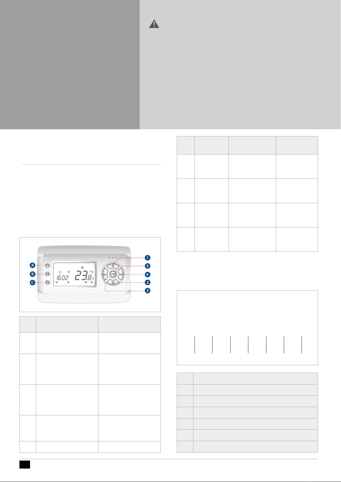
1.3.5 Alarm Display (AL)
1.3.6 Example of how to set the setpoint (SP)
Forexample,wewillmodifythesetpointinCOOLmodefrom12.0degreescentigradeto12.5de-
grees centigrade.
Setpoint edit function enable from main screen
Parameter Ui25 allows you to enable Set Point modication on the main display with the UP and
DOWNkeys.Forexample,wewillmodifythesetpointinCOOLmodefrom12.0degreescentigrade
to 12.5 degrees centigrade.
Parameter UI25=1 (folder Par/Ui/UI25) must be set.
See Parameters section (folder PAr)
Press the set key from the main display.
Label Ai appears on the display.
UsetheUPandDOWNkeysto
browse the other labels until you nd
the AL label.
Press the set key to view the label of
the rst active alarm (if it exists).
Inthiscase,therstalarmisEr01.
Scroll using the“up”and“down”keys
to nd other active alarms.
-------------------------------------
N.B.: the menu is not cyclical.
Forexample,iftheactivealarmsare
ER01,Er02andEr03,thedisplaywillshow:
Er01 ->Er02->Er03 <-Er02<-Er01
NOTE:->UP,<-DOWN
Press the esc key to go back to the
main display.
Tochangethesetpointonyour
machine,startingfromthemain
display,pressthesetkey.
Let’ssaywewanttochangetheCOOLmode
setpoint.
ThedevicemustbeinCOOLmode
(or in StdBy mode from COOL).
TochangethesetpointoftheHEATmode,
proceed in the same way by rst changing the
device”smodefromCOOLtoHEAT
See Operating Mode Menu chapter.
Tochangethesetpointonyourmachine,press
theUPorDOWNkeyinthemaindisplay
Label Ai appears on the display.
UsetheUPandDOWNkeysto
scroll the other labels until you
nd the SP label
Press the set key to open the SP
menu.
TherstdisplaywillbeCOOL
mode,andthenscrollingwiththe
UPandDOWNkeys,theHEAT
mode (the various displays are
shown at the side).
Let’ssaywewanttochangethe
COOL mode setpoint.
Press the set key beside the COOL
label.
Thedevicewillshowthecurrent
setpointofthemachine,whichis
12.0 degrees centigrade in this case).
- - -
Toincreaseordecreasethis,press
the“up”and“down”keys. For
example,ifyouwanttochange
thesetpointto12.5degrees,press
the“up arrow”key until you reach
therequiredvalue.
- - -
Torepeattheprocedurein
reverse until you get back to the
maindisplay,presstheesckeyor
wait for the 15-second timeout to elapse.
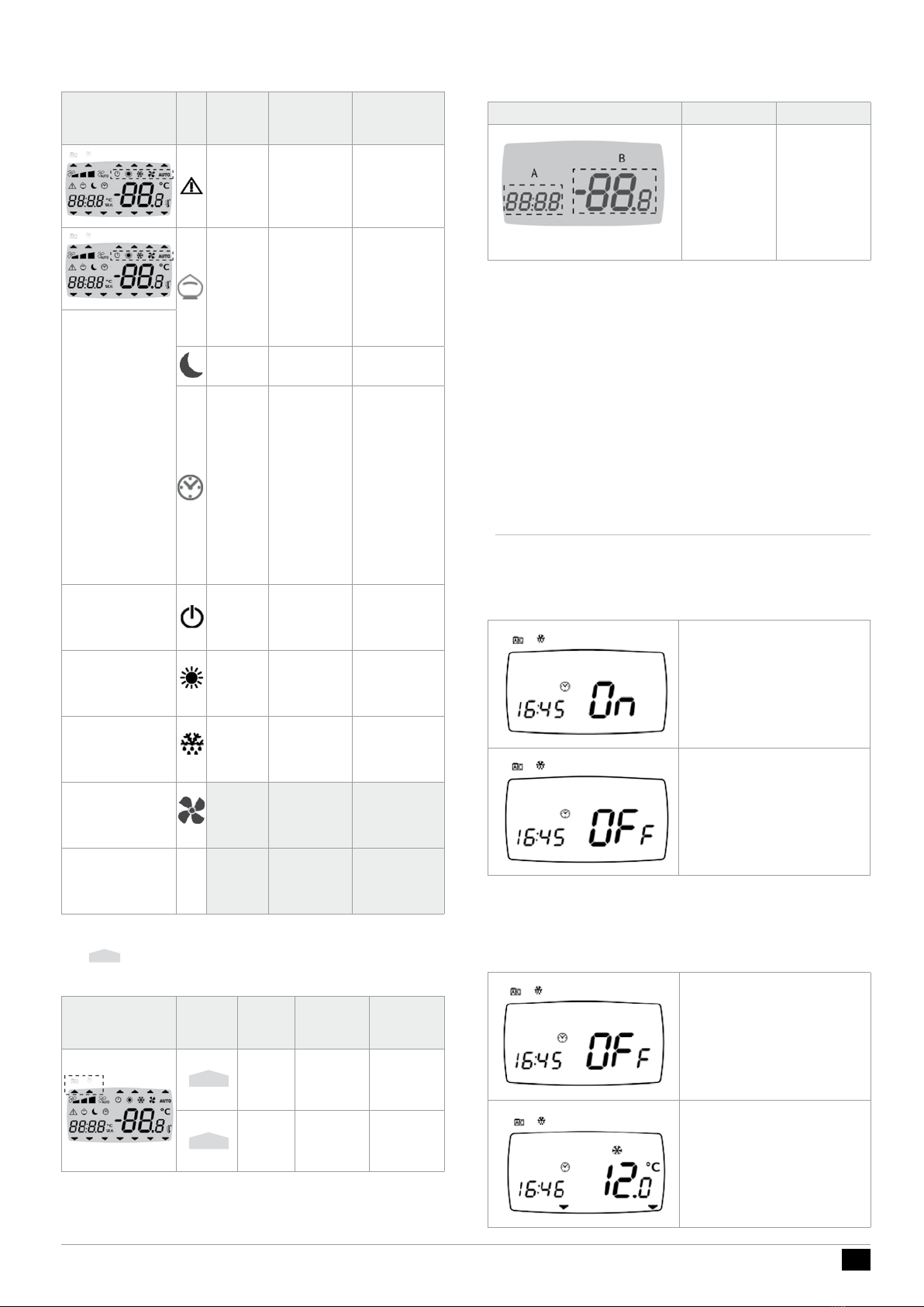
Change time/date/day menu
Note: Display A blinks.
Usethe“UP”and“DOWN”keys
toselectthetime,dateoryear.
Once you have decided what you
want to set (for example the
time),pressthesetkeyagainto
open the modication menu for
the variable selected.
- - -
Tosetthetime(thesame
procedure applies to the date
andyear),usethe“UP”and
“DOWN”keystoenterthe
requiredvalueandpressthe
- - -
Toexitthesettimemenu,press
the esc key until you are returned
to the main display.
Change time