AHRI RLNL-C 13 SEER Series User manual

INSTALLATION INSTRUCTIONS
Package Air Conditioners Featuring Industry
Standard R-410A Refrigerant
RLNL-C 13 SEER (3-5 TONS) SERIES
RLPL-C 14 SEER (3-5 TONS) SERIES
[ ] IN ICATES METRIC CONVERSION 92-23577-103-01
SUPERSE ES 92-23577-103-00
(14 SEER ONLY)
ISO 9001:2008

2
I. TABLE OF CONTENTS
I. Table of Contents ...........................................................................2
II. Introduction.....................................................................................3
III. Checking Product Received ...........................................................3
IV. Specifications .................................................................................3
A. General .....................................................................................3
B. Major Components....................................................................3
C. R-410A Refrigerant ...................................................................3
1. Specification of R-410A ........................................................3
2. Quick Reference Guide for R-410A ......................................3
3. Evaporator Coil/TXV .............................................................4
V. Equipment Protection .....................................................................4
Vi. Installation ......................................................................................7
1. Pre-Installation Check Points................................................7
2. Location ................................................................................7
B. Outside Slab Installation ...........................................................7
C. Clearances................................................................................8
. Rooftop Installation ...................................................................8
VII. uctwork ........................................................................................9
VIII. Filters............................................................................................10
IX. Conversion Procedure..................................................................10
X. Condensate rain ........................................................................10
XI. Electrical Wiring............................................................................11
A. Power Wiring ...........................................................................11
B. Special Instructions for Power Wiring with
Aluminum Conductors .............................................................11
C. Control Wiring .........................................................................12
. Internal Wiring.........................................................................13
E. Grounding ...............................................................................13
F. Thermostat..............................................................................13
XII. Indoor Air Flow ata.....................................................................14
XIII. Crankcase Heat............................................................................14
XIV. Pre-Start Check............................................................................14
XV. Startup..........................................................................................14
XVI. Operation......................................................................................15
XVII. Auxiliary Heat ...............................................................................15
XVIII. General ata...........................................................................16-23
XIX. Miscellaneous...............................................................................24
Electrical & Physical ata .......................................................24-27
Airflow Performance................................................................28-30
Heater Kit Characteristics .......................................................31-38
Wiring iagram.............................................................................39
Charge Charts.........................................................................40-44
Troubleshooting............................................................................45

3
II. INTRODUCTION
This booklet contains the installation and operating instructions for your package air con-
ditioner. There are a few precautions that should be taken to derive maximum satisfac-
tion from it. Improper installation can result in unsatisfactory operation or dangerous con-
ditions.
Read this booklet and any instructions packaged with separate equipment required to
make up the system prior to installation. Give this booklet to the owner and explain its
provisions. The owner should retain this booklet for future reference.
III. CHECKING PRODUCT RECEIVED
Upon receiving the unit, inspect it for any damage from shipment. Claims for damage,
either shipping or concealed, should be filed immediately with the shipping company.
Check the unit model number, electrical characteristics, and accessories to determine if
they are correct.
IV. SPECIFICATIONS
A. GENERAL
The Packaged Air Conditioner is available without heat or with 6, 10, 12, 15, 20 or 24
kW electric heat. Cooling capacities of 3, 31⁄2, 4 and 5 nominal tons of cooling are avail-
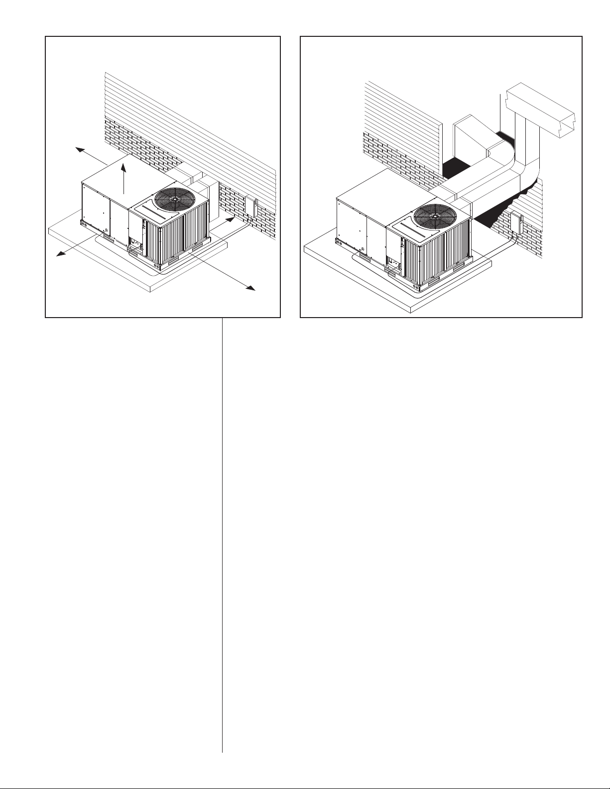
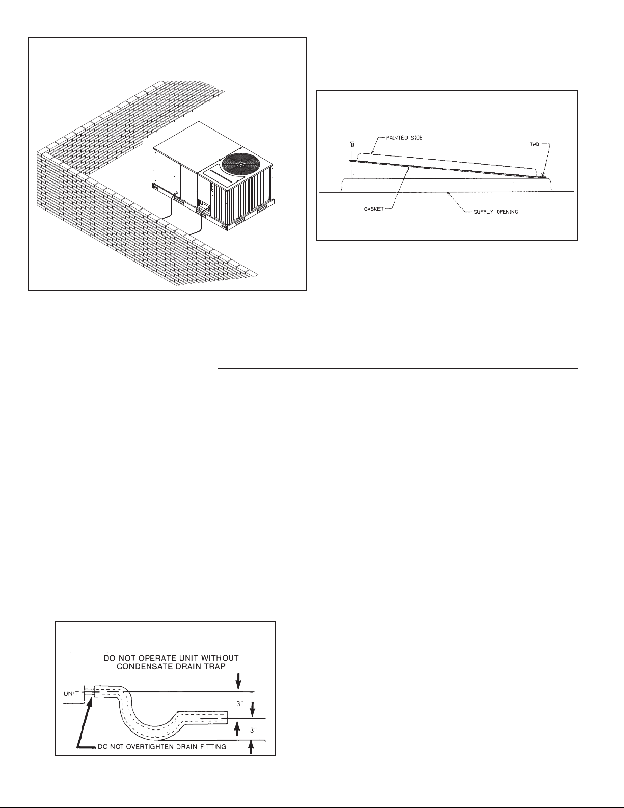
able. Units are convertible from end supply and return to bottom supply and return by
relocation of supply and return air access panels. See cover installation detail.
The units are weatherized for mounting outside of the building.
The information on the rating plate is in compliance with the FTC and OE rating for sin-
gle phase units. The following information is for three phase units which are not covered
under the OE certification program.
1. The efficiency rating of this unit is a product thermal efficiency rating determined
under continuous operating conditions independent of any installed system.
B. MAJOR COMPONENTS
The unit includes a hermetically-sealed refrigerating system (consisting of a compressor,
condenser coil, evaporator coil with thermal expansion valve), a circulation air blower, a
condenser fan, and all necessary internal electrical wiring. The cooling system of these
units is factory-evacuated, charged and performance tested. Refrigerant amount and
type are indicated on rating plate.
C. R-410A REFRIGERANT
All units are factory charged with R-410A refrigerant.
. Specification of R-4 0A:
Application: R-410A is not a drop-in replacement for R-22; equipment designs must
accommodate its higher pressures. It cannot be retrofitted into R-22 units.
Pressure: The pressure of R-410A is approximately 60% (1.6 times) greater than
R-22. Recovery and recycle equipment, pumps, hoses and the like need to have design
pressure ratings appropriate for R-410A. Manifold sets need to range u to 800 sig
high-side and 250 sig low-side with a 550 sig low-side retard. Hoses need to have a
service ressure rating of 800 sig. Recovery cylinders need to have a 400 sig service
ressure rating. OT 4BA400 or OT BW400.
Combustibility: At pressures above 1 atmosphere, mixture of R-410A and air can
become combustible. R-410A and air should never be mixed in tanks or supply
lines, or be allowed to accumulate in storage tanks. Leak checking should never
be done with a mixture of R-410A and air. Leak checking can be performed safely
with nitrogen or a mixture of R-410A and nitrogen.
2. Quick Reference Guide For R-4 0A
• R-410A refrigerant operates at approximately 60% higher pressure (1.6 times) than R-
22. Ensure that servicing equipment is designed to operate with R-410A.
• R-410A refrigerant cylinders are pink.
• R-410A, as with other HFC’s is only compatible with POE oils.
• Vacuum pumps will not remove moisture from POE oil.
!WARNING
PROPOSITION 65: THIS APPLI-
ANCE CONTAINS FIBERGLASS
INSULATION. RESPIRABLE
PARTICLES OF FIBERGLASS
ARE KNOWN TO THE STATE
OF CALIFORNIA TO CAUSE
CANCER..
!WARNING
THE MANUFACTURER’S WAR-
RANTY DOES NOT COVER ANY
DAMAGE OR DEFECT TO THE
AIR CONDITIONER CAUSED BY
THE ATTACHMENT OR USE OF
ANY COMPONENTS, ACCES-
SORIES OR DEVICES (OTHER
THAN THOSE AUTHORIZED BY
THE MANUFACTURER) INTO,
ONTO OR IN CON UNCTION
WITH THE AIR CONDITIONER.
YOU SHOULD BE AWARE THAT
THE USE OF UNAUTHORIZED
COMPONENTS, ACCESSORIES
OR DEVICES MAY ADVERSELY
AFFECT THE OPERATION OF
THE AIR CONDITIONER AND
MAY ALSO ENDANGER LIFE
AND PROPERTY. THE MANU-
FACTURER DISCLAIMS ANY
RESPONSIBILITY FOR SUCH
LOSS OR IN URY RESULTING
FROM THE USE OF SUCH
UNAUTHORIZED COMPO-
NENTS, ACCESSORIES OR
DEVICES.
Recognize this symbol as an indi-
cation of Important Safety
Information!
!

4
• R-410A systems are to be charged with liquid refrigerants. Prior to March 1999, R-
410A refrigerant cylinders had a dip tube. These cylinders should be kept upright for
equipment charging. Post March 1999 cylinders do not have a dip tube and should
be inverted to ensure liquid charging of the equipment.
• o not install a suction line filter drier in the liquid line.
• A liquid line filter drier is standard on every unit.
• esiccant (drying agent) must be compatible for POE oils and R-410A.
3. Evaporator Coil / TXV
The thermostatic expansion valve is specifically designed to operate with R-410A. DO
NOT use an R-22 TXV. The existin evaporator must be replaced with the factory
specified TXV evaporator specifically desi ned for R-410A.
4. Tools Required For Installing & Servicing R-4 0A Models
Manifold Sets:
-Up to 800 PSIG High side
-Up to 250 PSIG Low Side
-550 PSIG Low Side Retard
Manifold Hoses:
-Service Pressure Rating of 800 PSIG
Recovery Cylinders:
-400 PSIG Pressure Rating
- ept. of Transportation 4BA400 or BW400
V. EQUIPMENT PROTECTION FROM THE
ENVIRONMENT
The metal parts of this unit may be subject to rust or deterioration in adverse environ-
mental conditions. This oxidation could shorten the equipment’s useful life. Salt spray,
fog or mist in seacoast areas, sulphur or chlorine from lawn watering systems, and vari-
ous chemical contaminants from industries such as paper mills and petroleum refineries
are especially corrosive.
If the unit is to be installed in an area where contaminants are likely to be a prob-
lem, special attention should be given to the equipment location and exposure.
1. Avoid having lawn sprinkler heads spray direction on the unit cabinet.
2. In coastal areas, locate the unit on the side of the building away from the waterfront.
3. Shielding provided by a fence or shrubs may give some protection.
Regular maintenance will reduce the buildup of contaminents and help to protect
the unit’s finish.
1. Frequent washing of the cabinet, fan blade and coil with fresh water will remove
most of the salt or other contaminants that build up on the unit.
2. Regular cleaning and waxing of the cabinet with a good automobile polish will pro-
vide some protection.
3. A good liquid cleaner may be used several times a year to remove matter that will
not wash off with water.
Several different types of protective coatings are offered in some areas. These coatings
may provide some benefit, but the effectiveness of such coating materials cannot be ver-
ified by the equipment manufacturer.
The best protection is frequent cleaning, maintenance and minimal exposure to
contaminants.
!
CAUTION
R-410A systems operate at higher pressures than R-22 systems. o not use
R-22 service equipment or components on R-410A equipment.
!WARNING
DISCONNECT ALL POWER TO THE UNIT BEFORE STARTING MAINTE-
NANCE. FAILURE TO DO SO CAN RESULT IN SEVERE ELECTRICAL
SHOCK OR DEATH.

5
FIGURE 1
UNIT DIMENSIONS
BACK VIEW
SIDE VIEW FRONT VIEW
BOTTOM VIEW

FIGURE 2
UNIT VIEWS
6
SUPPLY COVER
RETURN COVER
CON ENSATE RAIN
3/4” NPT FEMALE
BLOWER
ACCESS
ELECTRIC HEAT
ACCESS
CONTROL BOX
ACCESS
COIL/FILTER
ACCESS

VI. INSTALLATION
A. GENERAL
1. PRE-INSTALLATION CHECK-POINTS
Before attempting any installation, the following points should be carefully consid-
ered:
a. Structural strength of supporting members.
(rooftop installation)
b. Clearances and provision for servicing.
c. Power supply and wiring.
d. Air duct connections.
e. rain facilities and connections.
f. Location for minimum noise.
2. LOCATION
These units are designed for outdoor installations. They can be mounted on a
slab or rooftop. They are not to be installed within any part of a structure such as
an attic, crawl space, closet, or any other place where condenser air flow is
restricted or other than outdoor ambient conditions prevail. Since the application
of the units is of the outdoor type, it is important to consult your local code authori-
ties at the time the first installation is made.
B. OUTSIDE SLAB INSTALLATION
(Typical out oor slab installations are shown in Figures 3 an 4.)
1. Select a location where external water drainage cannot collect around the unit.
2. Provide a level concrete slab extending 3" beyond all four sides of the unit. The
slab should be sufficient above grade to prevent ground water from entering the
unit. IMPORTANT: To revent transmission of noise or vibration, slab should not
be connected to building structure.
3. The location of the unit should be such as to provide proper access for inspection
and servicing.
4. Locate unit where operating sounds will not disturb owner or neighbors.
5. Locate unit so roof runoff water does not pour directly on the unit. Provide gutter
or other shielding at roof level. o not locate unit in an area where excessive
snow drifting may occur or accumulate.
6. Remove compressor shipping supports (if so equipped) after installation.
36“
60“
48“
VERTICAL
CLEARANCE
18“
12“
FIGURE 3
PACKAGE AIR CONDITIONER – OUTSI E SLAB INSTALLATION,
BASEMENT OR CRAWL SPACE ISTRIBUTION SYSTEM
FIGURE 4
PACKAGE AIR CONDITIONER – OUTSI E SLAB INSTALLATION, CLOSET
ISTRIBUTION SYSTEM. SLAB FLOOR CONSTRUCTION
*Allow 57" for
economizer on duct side.
7

C. CLEARANCES
The following minimum clearances must be observed for proper unit performance
and serviceability.
1. Provide 48" minimum clearance at the front of the unit. Provide 36" minimum
clearance at the left and right side of the unit for service access.
2. Provide 60" minimum clearance between top of unit and maximum 3 foot over-
hang.
3. Unit is design certified for application on combustible flooring with 0" minimum
clearance.
4. See Figure 3 for illustration of minimum installation-service clearances.
D. ROOFTOP INSTALLATION
1. Before locating the unit on the roof, make sure that the strength of the roof and
beams is adequate at that point to support the weight involved. (See specification
sheet for weight of unit.) This is very important and user’s responsibility.
2. For rigging and roofcurb details, see Figures 5 and 6. Use field-furnished spread-
ers.
3. For roofcurb assembly, see Roofcurb Installation Instructions.
4. If the roofcurb is not used, provisions for disposing of condensate water runoff
must be provided.
5. The unit should be placed on a solid and level roofcurb or platform of adequate
strength. See Figure 7.
6. The location of the unit on the roof should be such as to provide proper access for
inspection and servicing.
7. Remove compressor shipping supports (if so equipped) after installation.
IMPORTANT: If unit will not be ut into service immediately, cover su ly and return
o enings to revent excessive condensation.
ILL I296
A
B
C
38-1/4
CENTER
OF
GRAVITY
25-3/4
FIGURE 5
PACKAGE AIR CONDITIONER – RIGGING FOR LIFTING
CORNER WEIGHTS BY PERCENTAGE
AB C
23% 27% 23% 27%
8

VII.DUCTWORK
uctwork should be fabricated by the installing contractor in accordance with local codes
and NFPA90A. Industry manuals may be used as a guide when sizing and designing the
duct system - contact Air Conditioning Contractors of America, 2800 Shirlington Road,
Suite 300, Arlington, VA 22206, http://www.acca.org.
The unit should be placed as close to the space to be air conditioned as possible allow-
ing clearance dimensions as indicated. ucts should be run as directly as possible to
supply and return outlets. Use of non-flammable waterproof flexible connectors on both
supply and return connections at the unit to reduce noise transmission is recommended.
It is preferable to install the unit on the roof of the structure if the registers or diffusers
are located on the wall or in the ceiling. A slab installation could be considered when the
registers are low on a wall or in the floor.
On ductwork exposed to outside air conditions of temperature and humidity, use a mini-
mum of 2" of insulation and a vapor barrier. istribution system in attic, furred space or
crawl space should be insulated with at least 2" of insulation with vapor barrier. One-half
to 1" thickness of insulation is usually sufficient for ductwork inside the air conditioned
space.
Balancing dampers should be provided for each branch duct in the supply system.
uctwork should be properly supported from the structure.
When installing ductwork, consider the following items:
1. Noncombustible flexible connectors should be used between ductwork and unit to
reduce noise and vibration transmission into the ductwork.
2. When auxiliary heaters are installed, use noncombustible flexible connectors and
clearance to combustible material of 0" for the first 3 feet of discharge duct.
Clearance to unit top and side is 0".
!WARNING
DO NOT, UNDER ANY CIRCUM-
STANCES, CONNECT RETURN
DUCTWORK TO ANY OTHER HEAT
PRODUCING DEVICE SUCH AS A
FIREPLACE INSERT, STOVE, ETC.
UNAUTHORIZED USE OF SUCH
DEVICES MAY RESULT IN FIRE,
CARBON MONOXIDE POISONING,
EXPLOSION, PROPERTY DAMAGE,
SEVERE PERSONAL IN URY OR
DEATH.
ILL I301
FIGURE 6
PACKAGE AIR CONDITIONER – ROOFCURB INSTALLATION
9

VIII.FILTERS
This unit is provided with 2 - 25" x 16" x 1" disposable filters. When replacing filters,
ensure they are inserted fully to the back to prevent bypass.
IX. CONVERSION PROCEDURE
DOWNFLOW TO HORIZONTAL
1. Remove the screws and covers from the outside of the supply and return sections.
2. Install the covers in the bottom supply and return openings with the painted side up.
See Figure 8. Use the existing gasket to seal the covers.
3. Secure the supply cover to the base of the unit with 1 screw, engaging prepunched
tab in unit base.
4. Secure the return cover to the base of the unit with screws, engaging prepunched
holes in the unit base.
X. CONDENSATE DRAIN
The condensate drain connection of the evaporator is 3/4" nominal female pipe thread.
IMPORTANT: Install a condensate trap to ensure proper condensate drainage. See
Figure 9.
FIGURE 7
PACKAGE AIR CONDITIONER – FLAT ROOFTOP INSTALLATION, ATTIC OR
ROP CEILING ISTRIBUTION SYSTEM. MOUNTE ON ROOFCURB. CURB
MUST BE LEVEL
ILL I310
FIGURE 8
COVER GASKET DETAIL
ILL I631
FIGURE 9
CONDENSATE DRAIN
10

XI. ELECTRICAL WIRING
Field wiring must comply with the National Electrical Code* and local ordinances that
may apply.
*C.E.C. in Canada
A. POWER WIRING
1. It is important that proper electrical power is available at the unit. Voltage should
not vary more than 10% from that stamped on the unit rating plate. On three
phase units, phases must be balanced within 3%.
2. Install a branch circuit disconnect within sight of the unit and of adequate size to
handle the starting current. A bracket is shipped with the unit for mounting the dis-
connect. Reference Figure 10 for proper location.
3. For branch circuit wiring (main power supply to unit disconnect), the minimum
wire size can be determined from Table A using the circuit ampacity found on the
unit nameplate.
4. This unit incorporates single point electrical connection for unit and electric heat
accessory.
5. Power wiring must be run in grounded rain-tight conduit. Connect the power field
wiring as follows:
a. NO ELECTRIC HEAT - Connect the field wires directly to the contactor pigtail
in the electric heat access area. Connect ground wire to ground lug.
b. WITH ELECTRIC HEAT - Connect the field wires to the terminal block on the
electric heater kit in the electric heat access area. Connect the ground wire to
the ground lug on the heater kit.
NOTE: For field installation of a heater kit, follow the instructions provided with the
heater kit.
6. The pigtail wires in the electric heat access area are factory wired to the contactor
in the control box.
7. O NOT connect aluminum field wires to electric heat kit power input terminals.
B. SPECIAL INSTRUCTIONS FOR POWER WIRING WITH ALUMINUM
CONDUCTORS
1. Select the equivalent aluminum wire size from the tabulation below:
2. Attach a length (6" or more) of recommended size copper wire to the unit termi-
nals L1 and L3 for single phase, L1, L2, L3 for three phase.
TABLE B. WIRE SIZES
AWG Copper AWG Aluminum Connector Type and Size
Wire Size Wire Size (or equivalent)
#12 #10 T&B Wire Nut PT2
#10 #8 T&B Wire Nut PT3
#8 #6 Ilsco Split Bolt AK-6
#6 #4 Ilsco Split Bolt AK-4
#4 #2 Ilsco Split Bolt AK-2
#3 #1 Ilsco Split Bolt AK-1/0
#2 #0 Ilsco Split Bolt AK-1/0
#1 #00 Ilsco Split Bolt AK-2/0
#0 #000 Ilsco Split Bolt AK-4/0
COPPER WIRE SIZE — AWG (1% VOLTAGE DROP)
300
250
200
150
100
50
Supply
Wire
Length
Feet
Circuit Ampacity
NOTE:
1. Wire size based on 60ºC type copper conductors below 100 ampacity. 2. Wire size based on 75ºC type copper conductors for 100 ampacity and above.
4
4
6
8
10
14
15
3
4
4
6
8
12
20
2
3
4
6
8
10
25
2
3
4
4
6
10
30
1
2
3
4
6
8
35
1/0
1
2
4
6
8
40
1/0
1
2
3
4
6
45
2/0
1/0
1
3
4
6
50
2/0
1/0
1
2
4
6
55
3/0
2/0
1/0
2
3
4
60
3/0
2/0
1/0
1
3
4
65
3/0
2/0
1/0
1
2
4
70
4/0
3/0
2/0
1/0
2
3
75
4/0
3/0
2/0
1/0
2
3
80
4/0
3/0
2/0
1/0
1
3
85
4/0
4/0
3/0
1/0
1
2
90
250
4/0
3/0
2/0
1
2
95
250
4/0
3/0
2/0
1
2
100
250
4/0
3/0
2/0
1
2
105
250
4/0
3/0
2/0
1/0
2
110
300
250
4/0
2/0
1/0
1
115
300
250
4/0
3/0
1/0
1
120
300
250
4/0
3/0
1/0
1
125
300
250
4/0
3/0
1/0
1
130
300
250
4/0
3/0
1/0
1/0
135
350
350
300
4/0
1/0
1/0
140
350
350
300
4/0
2/0
1/0
145
350
350
300
4/0
2/0
1/0
150
350
350
300
4/0
2/0
2/0
155
TABLE A
11

3. Splice copper wire pigtails to aluminum wire with U.L. recognized connectors for
copper-aluminum splices. Follow these instructions very carefully to make a posi-
tive and lasting connection;
a. Strip insulation from aluminum conductor.
b. Coat the stripped end of the aluminum wire with the recommended inhibitor
and wire brush aluminum surface through inhibitor. Inhibitors: Brundy, Pentex
“A”; Alcoa, No. 2EJC; T&B KPOR Shield.
c. Clean and recoat aluminum conductor with inhibitor.
d. Make the splice using the above listed wire nuts or split bolt connectors.
e. Coat the entire connection with inhibitor and wrap with electrical insulating
tape.
WARRANTY MAY NOT APPLY IF CONNECTIONS ARE NOT MA E PER INSTRUC-
TIONS
C. CONTROL WIRING (Class II)
1. Low voltage wiring should not be run in conduit with power wiring.
2. Control wiring is routed through the 7/8" hole adjacent to the compressor access
panel. Use a minimum #18 AWG thermostat wire. For wire lengths exceeding 50',
use #16 AWG thermostat wire. The low voltage wires are connected to the unit
pigtails which are supplied with the unit in the low voltage connection box located
below the unit control box.
FIGURE 11
HEATER KIT INSTALLATION
FIGURE 10
RECOMMENDED LOCATION OF BRANCH CIRCUIT DISCONNECT
12

3. Figure 12 shows representative low voltage connection diagrams. Read your ther-
mostat installation instructions for any special requirements for your specific ther-
mostat.
NOTE — Units installed in Canada require that an outdoor thermostat (30,000
min. cycles of endurance) be installed and be wired with C.E.C. Class I wiring.
D. INTERNAL WIRING
IMPORTANT: Some single hase models are equi ed with a single ole contactor.
Caution must be exercised when servicing as only one leg of the ower su ly is
broken with the contactor.
Some models are equi ed with electronically commutated blower motors which are
constantly energized unless the main unit disconnect is in the off osition.
1. A diagram of the internal wiring of this unit is located on the inside of the com-
pressor access panel. If any of the original wire as supplied with the appliance
must be replaced, the wire gauge and insulation must be the same as original
wiring.
E. GROUNDING
F. THERMOSTAT
The thermostat should be mounted on an inside wall about five feet above the floor
in a location where it will not be affected by unconditioned air, sun, or drafts from
open doors or other sources. REA installation instructions in thermostat package
CAREFULLY because each has some different wiring requirements.
FIGURE 12
LOW VOLTAGE CONNECTIONS DIAGRAMS
!WARNING
THE UNIT MUST BE PERMANENTLY GROUNDED. A GROUNDING LUG IS
PROVIDED IN THE ELECTRIC HEAT KIT ACCESS AREA FOR A GROUND
WIRE. FAILURE TO GROUND THIS UNIT CAN RESULT IN FIRE OR ELECTRI-
CAL SHOCK CAUSING PROPERTY DAMAGE, SEVERE PERSONAL IN URY OR
DEATH.
13
R Y1 Y2 G C
ST-A1125-40-00
RTU-C BOARD LOW VOLTAGE
THERMOSTAT CONNECTIONS
OC B L
W1 W2
R Y1 Y2 G C W
NOTE: Y2 IS ONLY NECCESSARY FOR ECONOMIZER OPERATION
STANDARD WIRING

XII. INDOOR AIR FLOW DATA
irect-drive blower models are shipped factory wired for the proper speed at a typical
external static. See Blower Performance ata. Belt-drive blower models have motor
sheaves set for proper CFM at a typical external static.
XIII.CRANKCASE HEAT (OPTIONAL)
Crankcase heat is not required on scroll type compressors, but may be necessary for
difficult starting situations.
XIV.PRE-START CHECK
1. Is unit properly located and slightly slanted toward indoor condensate drain?
2. Is ductwork insulated, weatherproofed, with proper spacing to combustible materi-
als?
3. Is air free to travel to and from outdoor coil? (See Figure 3.)
4. Is the wiring correct, tight, and according to unit wiring diagram?
5. Is unit grounded?
6. Are field supplied air filters in place and clean?
7. o the outdoor fan and indoor blower turn freely without rubbing, and are they tight
on the motor shafts?
8. Are the compressor shipping supports removed (if so equipped)?
XV. STARTUP
1. Turn thermostat to “OFF,” turn “on” power supply at disconnect switch.
2. Turn temperature setting as high as it will go.
3. Turn fan switch to “ON.”
4. Indoor blower should run. Be sure it is running in the right direction.
5. Turn fan switch to “AUTO.” Turn system switch to “COOL” and turn temperature set-
ting below room temperature. Unit should run in cooling mode.
6. Is outdoor fan operating correctly in the right direction?
7. Is compressor running correctly.
8. Check the refrigerant charge using the instructions located on compressor access
panel. Replace service port caps. Service port cores are for system access only and
will leak if not tightly capped.
9. Turn thermostat system switch to proper mode “HEAT” or “COOl” and set thermostat
to proper temperature setting. Record the following after the unit has run some time.
A. Operating Mode _______________________________
B. ischarge Pressure (High)_PSIG
C. Vapor Pressure at Compressor (Low) __________PSIG
. VaporLine Temperature at Compressor ___________°F.
FIGURE 13
FLUSH MOUNT ROOM TEMPERATURE SENSOR FOR NETWORKED DDC APPLICATIONS
(REPLACES THERMOSTAT)
ROOM
TEMPERATURE
SENSOR WITH
TIMED OVERRIDE
BUTTON
ZNS-101
←10kΩroom tem-
perature sensor
transmits room tem-
perature to C
system. Times over-
ride buttons allows
tenant to change
from unoccupied
temperature setpoint
to occupied temper-
ature setpoint for a
preset time.
ROOM
TEMPERATURE
SENSOR WITH
TIMED OVERRIDE
BUTTON AND
STATUS INDICATOR
ZNS-102
←10kΩroom tem-
perature sensor
transmits room tem-
perature to C
system. Times over-
ride button allows
tenant to change
from unoccupied
temperature setpoint
to occupied temper-
ature setpoint for a
preset time. Status
Indicator Light trans-
mits ALARM flash
code to occupied
space.
ROOM
TEMPERATURE
SENSOR WITH
SETPOINT
AD USTMENT AND
TIMED OVERRIDE
BUTTON
ZNS-103
←10kΩroom tem-
perature sensor with
setpoint adjustment
transmits room tem-
perature to C
system along with
desired occupied
room temperature
setpoint. Timed
override button
allows tenant to
change from unoc-
cupied temperature
setpoint to occupied
temperature setpoint
for a preset time.
14

E. Indoor ry Bulb______________________________°F.
F. Indoor Wet Bulb _____________________________°F.
G. Outdoor ry Bulb ____________________________°F.
H. Outdoor Wet Bulb ____________________________°F.
I. Voltage at Contactor ________________________Volts
J. Current at Contactor _______________________Amps
K. Model Number_________________________________
L. Serial Number _________________________________
M.Location______________________________________
N. Owner _______________________________________
O. ate_________________________________________
10. Adjust discharge air grilles and balance system.
11. Check ducts for condensation and air leaks.
12. Check unit for tubing and sheet metal rattles.
13. Instruct the owner on operation and maintenance.
14. Leave “INSTALLATION” and ”USE AN CARE“ instructions with owner.
XVI.OPERATION
IMPORTANT: The com ressor has an internal overload rotector. Under some condi-
tions, it can take u to 2 hours for this overload to reset. Make sure overload has had
time to reset before condemning the com ressor.
XVII. AUXILIARY HEAT
CONTROL SYSTEM OPERATION
1. In the cooling mode, the thermostat will, on a call for cooling, energize the compres-
sor contactor and the indoor blower relay. The indoor blower can be operated contin-
uously by setting the thermostat fan switch at the “ON” position.
2. In the heating mode, the thermostat will energize one or more supplementary resis-
tance heaters.
!WARNING
ONLY ELECTRIC HEATER KITS SUPPLIED BY THIS MANUFACTURER AS
DESCRIBED IN THIS PUBLICATION HAVE BEEN DESIGNED, TESTED, AND
EVALUATED BY A NATIONALLY RECOGNIZED SAFETY TESTING AGENCY
FOR USE WITH THIS UNIT. USE OF ANY OTHER MANUFACTURED ELECTRIC
HEATERS INSTALLED WITHIN THIS UNIT MAY CAUSE HAZARDOUS CONDI-
TIONS RESULTING IN PROPERTY DAMAGE, FIRE, BODILY IN URY OR
DEATH.
15

XVIII. GENERAL DATA - RLNL MODELS
XVII. NOMINAL SIZES 3-5 TONS [10.6-17.6 kW]
NOTES:
1. Cooling Performance is rated at 95° F ambient, 80° F entering dry bulb, 67° F entering wet bulb. Gross capacity does not include the effect of fan motor heat. AHRI capaci-
ty is net and includes the effect of fan motor heat. Units are suitable for operation to ±20% of nominal cfm. Units are certified in accordance with the Unitary Air Conditioner
Equipment certification program, which is based on AHRI Standard 210/240 or 360.
2. EER and/or SEER are rated at AHRI conditions and in accordance with OE test procedures.
3. Outdoor Sound Rating shown is tested in accordance with AHRI Standard 270.
Model RLNL - Series C036CL C036CM C036DL C036DM
Coolin performance1
Gross Cooling Capacity Btu [kW] 36,800 [10.78] 36,800 [10.78] 36,800 [10.78] 36,800 [10.78]
EER, SEER211.4/13 11.4/13 11.4/13 11.4/13
Nominal CFM/AHRI Rated CFM [L/s] 1200/1200 [566/566] 1200/1200 [566/566] 1200/1200 [566/566] 1200/1200 [566/566]
AHRI Net Cooling Capacity Btu [kW] 35,400 [10.37] 35,400 [10.37] 35,400 [10.37] 35,400 [10.37]
Net Sensible Capacity Btu [kW] 26,200 [7.68] 26,200 [7.68] 26,200 [7.68] 26,200 [7.68]
Net Latent Capacity Btu [kW] 9,200 [2.7] 9,200 [2.7] 9,200 [2.7] 9,200 [2.7]
Net System Power kW 3.1 3.1 3.1 3.1
Compressor
No./Type 1/Scroll 1/Scroll 1/Scroll 1/Scroll
Outdoor Sound Ratin (dB)578 78 78 78
Outdoor Coil - Fin Type Louvered Louvered Louvered Louvered
Tube Type Rifled Rifled Rifled Rifled
Tube Size in. [mm] O 0.375 [9.5] 0.375 [9.5] 0.375 [9.5] 0.375 [9.5]
Face Area sq. ft. [sq. m] 16.91 [1.57] 16.91 [1.57] 16.91 [1.57] 16.91 [1.57]
Rows / FPI [FPcm] 1 / 22 [9] 1 / 22 [9] 1 / 22 [9] 1 / 22 [9]
Indoor Coil - Fin Type Corrugated Corrugated Corrugated Corrugated
Tube Type Rifled Rifled Rifled Rifled
Tube Size in. [mm] 0.375 [9.5] 0.375 [9.5] 0.375 [9.5] 0.375 [9.5]
Face Area sq. ft. [sq. m] 5.17 [0.48] 5.17 [0.48] 5.17 [0.48] 5.17 [0.48]
Rows / FPI [FPcm] 2 / 17 [7] 2 / 17 [7] 2 / 17 [7] 2 / 17 [7]
Refrigerant Control TX Valves TX Valves TX Valves TX Valves
rain Connection No./Size in. [mm] 1/0.75 [19.05] 1/0.75 [19.05] 1/0.75 [19.05] 1/0.75 [19.05]
Outdoor Fan - Type Propeller Propeller Propeller Propeller
No. Used/ iameter in. [mm] 1/24 [609.6] 1/24 [609.6] 1/24 [609.6] 1/24 [609.6]
rive Type/No. Speeds irect/1 irect/1 irect/1 irect/1
CFM [L/s] 3680 [1737] 3680 [1737] 3680 [1737] 3680 [1737]
No. Motors/HP 1 at 1/3 HP 1 at 1/3 HP 1 at 1/3 HP 1 at 1/3 HP
Motor RPM 1075 1075 1075 1075
Indoor Fan - Type FC Centrifugal FC Centrifugal FC Centrifugal FC Centrifugal
No. Used/ iameter in. [mm] 1/10x10 [254x254] 1/10x10 [254x254] 1/10x10 [254x254] 1/10x10 [254x254]
rive Type/No. Speeds Belt/Variable Belt/Variable Belt/Variable Belt/Variable
No. Motors 1111
Motor HP 1/2 1/2 1/2 1/2
Motor RPM 1725 1725 1725 1725
Motor Frame Size 48 56 48 56
Filter - Type isposable isposable isposable isposable
Furnished Yes Yes Yes Yes
(NO.) Size Recommended in. [mm x mm x mm] (1)1x16x25 [25x406x635] (1)1x16x25 [25x406x635] (1)1x16x25 [25x406x635] (1)1x16x25 [25x406x635]
(1)1x16x25 [25x406x635] (1)1x16x25 [25x406x635] (1)1x16x25 [25x406x635]] (1)1x16x25 [25x406x635]
Refri erant Char e Oz. [ ] 96 [2722] 96 [2722] 96 [2722] 96 [2722]
Wei hts
Net Weight lbs. [kg] 543 [246] 543 [246] 543 [246] 543 [246]
Ship Weight lbs. [kg] 550 [249] 550 [249] 550 [249] 550 [249]
Continued ->
16

GENERAL DATA - RLNL MODELS
NOMINAL SIZES 3-5 TONS [10.6-17.6 kW]
NOTES:
1. Cooling Performance is rated at 95° F ambient, 80° F entering dry bulb, 67° F entering wet bulb. Gross capacity does not include the effect of fan motor heat. AHRI capaci-
ty is net and includes the effect of fan motor heat. Units are suitable for operation to ±20% of nominal cfm. Units are certified in accordance with the Unitary Air Conditioner
Equipment certification program, which is based on AHRI Standard 210/240 or 360.
2. EER and/or SEER are rated at AHRI conditions and in accordance with OE test procedures.
3. Outdoor Sound Rating shown is tested in accordance with AHRI Standard 270.
Model RLNL - Series C042CL C042CM C042DL C042DM
Coolin performance1
Gross Cooling Capacity Btu [kW] 42,500 [12.45] 42,500 [12.45] 42,500 [12.45] 42,500 [12.45]
EER, SEER211.2/13 11.2/13 11.2/13 11.2/13
Nominal CFM/AHRI Rated CFM [L/s] 1400/1450 [661/684] 1400/1450 [661/684] 1400/1450 [661/684] 1400/1450 [661/684]
AHRI Net Cooling Capacity Btu [kW] 40,500 [11.87] 40,500 [11.87] 40,500 [11.87] 40,500 [11.87]
Net Sensible Capacity Btu [kW] 30,600 [8.97] 30,600 [8.97] 30,600 [8.97] 30,600 [8.97]
Net Latent Capacity Btu [kW] 9,900 [2.9] 9,900 [2.9] 9,900 [2.9] 9,900 [2.9]
Net System Power kW 3.62 3.62 3.62 3.62
Compressor
No./Type 1/Scroll 1/Scroll 1/Scroll 1/Scroll
Outdoor Sound Ratin (dB)578 78 78 78
Outdoor Coil - Fin Type Louvered Louvered Louvered Louvered
Tube Type Rifled Rifled Rifled Rifled
Tube Size in. [mm] O 0.375 [9.5] 0.375 [9.5] 0.375 [9.5] 0.375 [9.5]
Face Area sq. ft. [sq. m] 16.91 [1.57] 16.91 [1.57] 16.91 [1.57] 16.91 [1.57]
Rows / FPI [FPcm] 1.53 / 22 [9] 1.53 / 22 [9] 1.53 / 22 [9] 1.53 / 22 [9]
Indoor Coil - Fin Type Corrugated Corrugated Corrugated Corrugated
Tube Type Rifled Rifled Rifled Rifled
Tube Size in. [mm] 0.375 [9.5] 0.375 [9.5] 0.375 [9.5] 0.375 [9.5]
Face Area sq. ft. [sq. m] 5.17 [0.48] 5.17 [0.48] 5.17 [0.48] 5.17 [0.48]
Rows / FPI [FPcm] 3 / 13 [5] 3 / 13 [5] 3 / 13 [5] 3 / 13 [5]
Refrigerant Control TX Valves TX Valves TX Valves TX Valves
rain Connection No./Size in. [mm] 1/0.75 [19.05] 1/0.75 [19.05] 1/0.75 [19.05] 1/0.75 [19.05]
Outdoor Fan - Type Propeller Propeller Propeller Propeller
No. Used/ iameter in. [mm] 1/24 [609.6] 1/24 [609.6] 1/24 [609.6] 1/24 [609.6]
rive Type/No. Speeds irect/1 irect/1 irect/1 irect/1
CFM [L/s] 3680 [1737] 3680 [1737] 3680 [1737] 3680 [1737]
No. Motors/HP 1 at 1/3 HP 1 at 1/3 HP 1 at 1/3 HP 1 at 1/3 HP
Motor RPM 1075 1075 1075 1075
Indoor Fan - Type FC Centrifugal FC Centrifugal FC Centrifugal FC Centrifugal
No. Used/ iameter in. [mm] 1/10x10 [254x254] 1/10x10 [254x254] 1/10x10 [254x254] 1/10x10 [254x254]
rive Type/No. Speeds Belt/Variable Belt/Variable Belt/Variable Belt/Variable
No. Motors 1111
Motor HP 1/2 3/4 1/2 3/4
Motor RPM 1725 1725 1725 1725
Motor Frame Size 48 56 48 56
Filter - Type isposable isposable isposable isposable
Furnished Yes Yes Yes Yes
(NO.) Size Recommended in. [mm x mm x mm] (1)1x16x25 [25x406x635] (1)1x16x25 [25x406x635] (1)1x16x25 [25x406x635] (1)1x16x25 [25x406x635]
(1)1x16x25 [25x406x635] (1)1x16x25 [25x406x635] (1)1x16x25 [25x406x635]] (1)1x16x25 [25x406x635]
Refri erant Char e Oz. [ ] 125 [3544] 125 [3544] 125 [3544] 125 [3544]
Wei hts
Net Weight lbs. [kg] 570 [259] 570 [259] 570 [259] 570 [259]
Ship Weight lbs. [kg] 577 [262] 577 [262] 577 [262] 577 [262]
Continued ->
17

GENERAL DATA - RLNL MODELS
NOMINAL SIZES 3-5 TONS [10.6-17.6 kW]
NOTES:
1. Cooling Performance is rated at 95° F ambient, 80° F entering dry bulb, 67° F entering wet bulb. Gross capacity does not include the effect of fan motor heat. AHRI capaci-
ty is net and includes the effect of fan motor heat. Units are suitable for operation to ±20% of nominal cfm. Units are certified in accordance with the Unitary Air Conditioner
Equipment certification program, which is based on AHRI Standard 210/240 or 360.
2. EER and/or SEER are rated at AHRI conditions and in accordance with OE test procedures.
3. Outdoor Sound Rating shown is tested in accordance with AHRI Standard 270.
Model RLNL - Series C048CL C048CM C048DL C048DM
Coolin performance1
Gross Cooling Capacity Btu [kW] 50,000 [14.65] 50,000 [14.65] 50,000 [14.65] 50,000 [14.65]
EER, SEER211.45/13 11.45/13 11.45/13 11.45/13
Nominal CFM/AHRI Rated CFM [L/s] 1600/1600 [755/755] 1600/1600 [755/755] 1600/1600 [755/755] 1600/1600 [755/755]
AHRI Net Cooling Capacity Btu [kW] 48,000 [14.06] 48,000 [14.06] 48,000 [14.06] 48,000 [14.06]
Net Sensible Capacity Btu [kW] 35,600 [10.43] 35,600 [10.43] 35,600 [10.43] 35,600 [10.43]
Net Latent Capacity Btu [kW] 12,400 [3.63] 12,400 [3.63] 12,400 [3.63] 12,400 [3.63]
Net System Power kW 4.19 4.19 4.19 4.19
Compressor
No./Type 1/Scroll 1/Scroll 1/Scroll 1/Scroll
Outdoor Sound Ratin (dB)578 78 78 78
Outdoor Coil - Fin Type Louvered Louvered Louvered Louvered
Tube Type Rifled Rifled Rifled Rifled
Tube Size in. [mm] O 0.375 [9.5] 0.375 [9.5] 0.375 [9.5] 0.375 [9.5]
Face Area sq. ft. [sq. m] 16.56 [1.54] 16.56 [1.54] 16.56 [1.54] 16.56 [1.54]
Rows / FPI [FPcm] 2 / 22 [9] 2 / 22 [9] 2 / 22 [9] 2 / 22 [9]
Indoor Coil - Fin Type Corrugated Corrugated Corrugated Corrugated
Tube Type Rifled Rifled Rifled Rifled
Tube Size in. [mm] 0.375 [9.5] 0.375 [9.5] 0.375 [9.5] 0.375 [9.5]
Face Area sq. ft. [sq. m] 5.17 [0.48] 5.17 [0.48] 5.17 [0.48] 5.17 [0.48]
Rows / FPI [FPcm] 3 / 15 [6] 3 / 15 [6] 3 / 15 [6] 3 / 15 [6]
Refrigerant Control TX Valves TX Valves TX Valves TX Valves
rain Connection No./Size in. [mm] 1/0.75 [19.05] 1/0.75 [19.05] 1/0.75 [19.05] 1/0.75 [19.05]
Outdoor Fan - Type Propeller Propeller Propeller Propeller
No. Used/ iameter in. [mm] 1/24 [609.6] 1/24 [609.6] 1/24 [609.6] 1/24 [609.6]
rive Type/No. Speeds irect/1 irect/1 irect/1 irect/1
CFM [L/s] 3680 [1737] 3680 [1737] 3680 [1737] 3680 [1737]
No. Motors/HP 1 at 1/3 HP 1 at 1/3 HP 1 at 1/3 HP 1 at 1/3 HP
Motor RPM 1075 1075 1075 1075
Indoor Fan - Type FC Centrifugal FC Centrifugal FC Centrifugal FC Centrifugal
No. Used/ iameter in. [mm] 1/10x10 [254x254] 1/10x10 [254x254] 1/10x10 [254x254] 1/10x10 [254x254]
rive Type/No. Speeds Belt/Variable Belt/Variable Belt/Variable Belt/Variable
No. Motors 1111
Motor HP 1/2 1/2 1/2 3/4
Motor RPM 1725 1725 1725 1725
Motor Frame Size 48 56 48 56
Filter - Type isposable isposable isposable isposable
Furnished Yes Yes Yes Yes
(NO.) Size Recommended in. [mm x mm x mm] (1)1x16x25 [25x406x635] (1)1x16x25 [25x406x635] (1)1x16x25 [25x406x635] (1)1x16x25 [25x406x635]
(1)1x16x25 [25x406x635] (1)1x16x25 [25x406x635] (1)1x16x25 [25x406x635] (1)1x16x25 [25x406x635]
Refri erant Char e Oz. [ ] 165 [4678] 165 [4678] 165 [4678] 165 [4678]
Wei hts
Net Weight lbs. [kg] 580 [263] 580 [263] 580 [263] 580 [263]
Ship Weight lbs. [kg] 587 [266] 587 [266] 587 [266] 587 [266]
Continued ->
18

GENERAL DATA - RLNL MODELS
NOMINAL SIZES 3-5 TONS [10.6-17.6 kW]
NOTES:
1. Cooling Performance is rated at 95° F ambient, 80° F entering dry bulb, 67° F entering wet bulb. Gross capacity does not include the effect of fan motor heat. AHRI capaci-
ty is net and includes the effect of fan motor heat. Units are suitable for operation to ±20% of nominal cfm. Units are certified in accordance with the Unitary Air Conditioner
Equipment certification program, which is based on AHRI Standard 210/240 or 360.
2. EER and/or SEER are rated at AHRI conditions and in accordance with OE test procedures.
3. Outdoor Sound Rating shown is tested in accordance with AHRI Standard 270.
Model RLNL - Series C060CL C060CM C060DL C060DM
Coolin performance1
Gross Cooling Capacity Btu [kW] 61,000 [17.87] 61,000 [17.87] 61,000 [17.87] 61,000 [17.87]
EER, SEER211.1/13 11.1/13 11.1/13 11.1/13
Nominal CFM/AHRI Rated CFM [L/s] 2000/1900 [944/897] 2000/1900 [944/897] 2000/1900 [944/897] 2000/1900 [944/897]
AHRI Net Cooling Capacity Btu [kW] 59,000 [17.29] 59,000 [17.29] 59,000 [17.29] 59,000 [17.29]
Net Sensible Capacity Btu [kW] 42,000 [12.31] 42,000 [12.31] 42,000 [12.31] 42,000 [12.31]
Net Latent Capacity Btu [kW] 17,000 [4.98] 17,000 [4.98] 17,000 [4.98] 17,000 [4.98]
Net System Power kW 5.32 5.32 5.32 5.32
Compressor
No./Type 1/Scroll 1/Scroll 1/Scroll 1/Scroll
Outdoor Sound Ratin (dB)583 83 83 83
Outdoor Coil - Fin Type Louvered Louvered Louvered Louvered
Tube Type Rifled Rifled Rifled Rifled
Tube Size in. [mm] O 0.375 [9.5] 0.375 [9.5] 0.375 [9.5] 0.375 [9.5]
Face Area sq. ft. [sq. m] 16.56 [1.54] 16.56 [1.54] 16.56 [1.54] 16.56 [1.54]
Rows / FPI [FPcm] 2 / 22 [9] 2 / 22 [9] 2 / 22 [9] 2 / 22 [9]
Indoor Coil - Fin Type Corrugated Corrugated Corrugated Corrugated
Tube Type Rifled Rifled Rifled Rifled
Tube Size in. [mm] 0.375 [9.5] 0.375 [9.5] 0.375 [9.5] 0.375 [9.5]
Face Area sq. ft. [sq. m] 5.17 [0.48] 5.17 [0.48] 5.17 [0.48] 5.17 [0.48]
Rows / FPI [FPcm] 3 / 15 [6] 3 / 15 [6] 3 / 15 [6] 3 / 15 [6]
Refrigerant Control TX Valves TX Valves TX Valves TX Valves
rain Connection No./Size in. [mm] 1/0.75 [19.05] 1/0.75 [19.05] 1/0.75 [19.05] 1/0.75 [19.05]
Outdoor Fan - Type Propeller Propeller Propeller Propeller
No. Used/ iameter in. [mm] 1/24 [609.6] 1/24 [609.6] 1/24 [609.6] 1/24 [609.6]
rive Type/No. Speeds irect/1 irect/1 irect/1 irect/1
CFM [L/s] 3930 [1855] 3930 [1855] 3930 [1855] 3930 [1855]
No. Motors/HP 1 at 1/3 HP 1 at 1/3 HP 1 at 1/3 HP 1 at 1/3 HP
Motor RPM 1075 1075 1075 1075
Indoor Fan - Type FC Centrifugal FC Centrifugal FC Centrifugal FC Centrifugal
No. Used/ iameter in. [mm] 1/10x10 [254x254] 1/10x10 [254x254] 1/10x10 [254x254] 1/10x10 [254x254]
rive Type/No. Speeds Belt/Variable Belt/Variable Belt/Variable Belt/Variable
No. Motors 1111
Motor HP 3/4 1 3/4 1
Motor RPM 1725 1725 1725 1725
Motor Frame Size 56 56 56 56
Filter - Type isposable isposable isposable isposable
Furnished Yes Yes Yes Yes
(NO.) Size Recommended in. [mm x mm x mm] (1)1x16x25 [25x406x635] (1)1x16x25 [25x406x635] (1)1x16x25 [25x406x635] (1)1x16x25 [25x406x635]
(1)1x16x25 [25x406x635] (1)1x16x25 [25x406x635] (1)1x16x25 [25x406x635] (1)1x16x25 [25x406x635]
Refri erant Char e Oz. [ ] 160 [4536] 160 [4536] 160 [4536] 160 [4536]
Wei hts
Net Weight lbs. [kg] 590 [268] 590 [268] 590 [268] 590 [268]
Ship Weight lbs. [kg] 597 [271] 597 [271] 597 [271] 597 [271]
Continued ->
19

GENERAL DATA - RLPL MODELS
NOMINAL SIZES 3-5 TONS [10.6-17.6 kW]
NOTES:
1. Cooling Performance is rated at 95° F ambient, 80° F entering dry bulb, 67° F entering wet bulb. Gross capacity does not include the effect of fan motor heat. AHRI capaci-
ty is net and includes the effect of fan motor heat. Units are suitable for operation to ±20% of nominal cfm. Units are certified in accordance with the Unitary Air Conditioner
Equipment certification program, which is based on AHRI Standard 210/240 or 360.
2. EER and/or SEER are rated at AHRI conditions and in accordance with OE test procedures.
3. Outdoor Sound Rating shown is tested in accordance with AHRI Standard 270.
Model RLPL - Series C036CL C036CM C036DL C036DM
Coolin performance1
Gross Cooling Capacity Btu [kW] 36,600 [10.72] 36,600 [10.72] 36,600 [10.72] 36,600 [10.72]
EER, SEER212.05/14 12.05/14 12.05/14 12.05/14
Nominal CFM/AHRI Rated CFM [L/s] 1200/1200 [566/566] 1200/1200 [566/566] 1200/1200 [566/566] 1200/1200 [566/566]
AHRI Net Cooling Capacity Btu [kW] 35,800 [10.49] 35,800 [10.49] 35,800 [10.49] 35,800 [10.49]
Net Sensible Capacity Btu [kW] 27,000 [7.91] 27,000 [7.91] 27,000 [7.91] 27,000 [7.91]
Net Latent Capacity Btu [kW] 8,800 [2.58] 8,800 [2.58] 8,800 [2.58] 8,800 [2.58]
Net System Power kW 2.97 2.97 2.97 2.97
Compressor
No./Type 1/Scroll 1/Scroll 1/Scroll 1/Scroll
Outdoor Sound Ratin (dB)578 78 78 78
Outdoor Coil - Fin Type Louvered Louvered Louvered Louvered
Tube Type Rifled Rifled Rifled Rifled
Tube Size in. [mm] O 0.375 [9.5] 0.375 [9.5] 0.375 [9.5] 0.375 [9.5]
Face Area sq. ft. [sq. m] 16.91 [1.57] 16.91 [1.57] 16.91 [1.57] 16.91 [1.57]
Rows / FPI [FPcm] 1 / 22 [9] 1 / 22 [9] 1 / 22 [9] 1 / 22 [9]
Indoor Coil - Fin Type Corrugated Corrugated Corrugated Corrugated
Tube Type Rifled Rifled Rifled Rifled
Tube Size in. [mm] 0.375 [9.5] 0.375 [9.5] 0.375 [9.5] 0.375 [9.5]
Face Area sq. ft. [sq. m] 5.17 [0.48] 5.17 [0.48] 5.17 [0.48] 5.17 [0.48]
Rows / FPI [FPcm] 2 / 17 [7] 2 / 17 [7] 2 / 17 [7] 2 / 17 [7]
Refrigerant Control TX Valves TX Valves TX Valves TX Valves
rain Connection No./Size in. [mm] 1/0.75 [19.05] 1/0.75 [19.05] 1/0.75 [19.05] 1/0.75 [19.05]
Outdoor Fan - Type Propeller Propeller Propeller Propeller
No. Used/ iameter in. [mm] 1/24 [609.6] 1/24 [609.6] 1/24 [609.6] 1/24 [609.6]
rive Type/No. Speeds irect/1 irect/1 irect/1 irect/1
CFM [L/s] 3680 [1737] 3680 [1737] 3680 [1737] 3680 [1737]
No. Motors/HP 1 at 1/3 HP 1 at 1/3 HP 1 at 1/3 HP 1 at 1/3 HP
Motor RPM 1075 1075 1075 1075
Indoor Fan - Type FC Centrifugal FC Centrifugal FC Centrifugal FC Centrifugal
No. Used/ iameter in. [mm] 1/10x10 [254x254] 1/10x10 [254x254] 1/10x10 [254x254] 1/10x10 [254x254]
rive Type/No. Speeds Belt/Variable Belt/Variable Belt/Variable Belt/Variable
No. Motors 1111
Motor HP 1/2 1/2 1/2 1/2
Motor RPM 1725 1725 1725 1725
Motor Frame Size 48 56 48 56
Filter - Type isposable isposable isposable isposable
Furnished Yes Yes Yes Yes
(NO.) Size Recommended in. [mm x mm x mm] (1)1x16x25 [25x406x635] (1)1x16x25 [25x406x635] (1)1x16x25 [25x406x635] (1)1x16x25 [25x406x635]
(1)1x16x25 [25x406x635] (1)1x16x25 [25x406x635] (1)1x16x25 [25x406x635]] (1)1x16x25 [25x406x635]
Refri erant Char e Oz. [ ] 96 [2722] 96 [2722] 96 [2722] 96 [2722]
Wei hts
Net Weight lbs. [kg] 543 [246] 543 [246] 543 [246] 543 [246]
Ship Weight lbs. [kg] 550 [249] 550 [249] 550 [249] 550 [249]
Continued ->
20
This manual suits for next models
1
Table of contents
Other AHRI Air Conditioner manuals
Popular Air Conditioner manuals by other brands

Daikin
Daikin Comfort Flex CLIV Series Installation, operation and maintenance manual

Dimplex
Dimplex DCEVP5WG instruction manual

Mitsubishi Electric
Mitsubishi Electric Mr.Slim MS-GK36VA operating instructions

Sharp
Sharp AH-AP18DR Service manual

Mitsubishi
Mitsubishi Mr.Slim PKA-A-GA installation manual

Arctic King
Arctic King wwk05cr61n Energy guide