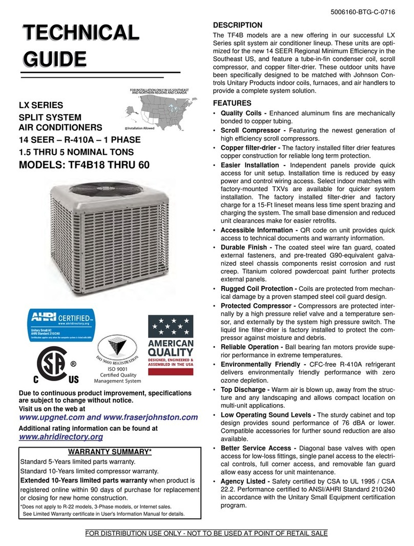
AHRI U-match Series User guide

April 2022 MS-SVN083A-EN
Installer’s Manual
DC Inverter U-match Series for R410A Unitary
Split Air Conditioner
Models:
HP Outdoor Units:
4TXD2036A10NUA
4TXD2060A10NUA
HP Indoor Units:
4MXA2024A10NUA
4MXA2036A10NUA
4MXA2048A10NUA
4MXA2060A10NUA

Warnings and Cautions
Warnings are provided to alert others of the potential hazards that could result in severe
personal injury or death, while cautions are designed to alert others of the conditions that
could result in minor or moderate injury.
Your personal safety and the proper operation of this machine depend upon the strict
observance of these precautions.
WARNING
This equipment is to be serviced by professionally trained personnel ONLY. Under NO
circumstances should an unqualified person service it.This equipment contains refrigerant
under PRESSURE and operates at HIGH VOLTAGE. Improperly installed, adjusted or altered
equipment by an unqualified person poses safety hazards including FIRE, ELECTROCUTION,
or EXPLOSION, which could result in death or serious injury.
WARNING
Electrocution and Fire Hazards with Improperly Installed and Grounded Field Wiring!
Improperly installed and grounded field wiring poses FIRE and ELECTROCUTION hazards.
To avoid these hazards, you MUST follow requirements for field wiring installation and
grounding as described in the National Electrical Codes (NEC) and your State and/or local
electrical codes. All field wiring MUST be performed by qualified personnel.
Failure to follow these requirements could result in death or serious injury.
WARNING
R410-A Refrigerant under Higher Pressure than R-22!
The units described in this manual use R410-A refrigerant which operates at 50 to 70% higher
pressures than R-22. Use only R-410A approved service equipment. Refrigerant cylinders
are painted with "pink" color to indicate the type of refrigerant and may contain a "dip" tube
to allow for charging of liquid refrigerant into the system. For specific handling concerns
with R-410A, please contact your local sales office.
Failure to use R-410A approved service equipment could result in standard equipment
exploding under R-410A higher pressure which could result in death or serious injury.
WARNING
This product can expose you to chemicals including lead, which are known to the State of
California to cause cancer and birth defects or other reproductive harm. For more information
go to www.P65Warnings.ca.gov
Attention Warnings and Cautions appear at appropriate sections throughout this literature.
Read these carefully.
WARNING This mark indicates a potentially hazardous situation which, if not avoided, could
result in death or serious injury.
CAUTION
This mark indicates a potentially hazardous situation which, if not avoided, could
result in minor or moderate injury. It may also be used to alert against unsafe
practices.
NOTICE This mark indicates a situation which could result in equipment and/or property
damage.

USE ONLY THE FACTORY RECOMMENDED OIL TYPE!
Warnings are provided to alert others of the potential hazards that could result in severe
personal injury or death, while cautions are designed to alert others of the conditions that
could result in minor or moderate injury.
Your personal safety and the proper operation of this machine depend upon the strict
observance of these precautions.
Important!
Environmental Concerns
Scientific research has shown that certain man-made chemicals can affect the earth's naturally
occurring stratospheric ozone layer when released to the atmosphere. In particular, several
of the identified chemicals that may affect the ozone layer are refrigerants that contain
chlorofluorocarbons (CFC's) and those containing hydro-chlorofluorocarbons (HCFC's).
Not all refrigerants containing these compounds have the same potential impact to the
environment.The Company advocates the responsible handling of all refrigerants, including
industry replacements for CFC's such as HCFC's and HFC's.
Responsible Refrigerant Practices
The manufacturer believes that responsible refrigerant practices are important to the
environment, our customers, and the air conditioning industry. All technicians who handle
refrigerants must be certified.The Federal CleanAirAct (Section 608) sets forth the requirements
for handling, reclaiming, recovering and recycling of certain refrigerants and the equipment
that is used in these service procedures. In addition, some states or municipalities may
have additional requirements that must also be adhered to for responsible management of
refrigerants. Know the applicable laws and follow them.
NOTICE
Use appropriate oil with R410A systems. Oil type is found at the bottom of Connection Pipe
Requirements table (included in the outdoor unit installation manual). R-410A systems utilize POE
(Polyolester) or PVE(Polyvinyl Ether) oil. Both oil types absorb moisture readily, yet, lubrication
properties vary. Do not leave the sealed system open to atmosphere except during service for a
short period of time. If the sealed system is left open longer than four hours, the compressor oil
must be changed. These systems utilize strainers placed before and after the expansion device in
the outdoor unit, if debris or moisture is suspected, these strainers must be changed. Do not break
a vacuum with air. Do not leak check the sealed system with compressed air. Unless instructed by
factory service representative, external refrigeration driers are prohibited.

Contents
Safety Precautions.................................................................................................................................5
Product Introduction ............................................................................................................................7
Operating Range ...............................................................................................................................7
Standard Accessories ......................................................................................................................7
Installation ............................................................................................................................................8
Installation Preparation ....................................................................................................................8
Selection of Installation Location ..............................................................................................8
Unit Dimension ...........................................................................................................................8
Unit Installation .................................................................................................................................9
Outdoor Unit Installation ...........................................................................................................9
Condensate Management of the Outdoor Unit ......................................................................10
Connection Pipe Installation .................................................................................................... 11
Flaring Process ..........................................................................................................................12
Bending Pipes ............................................................................................................................12
Refrigerant Piping at the Outdoor Unit ...................................................................................13
Insulating the Refrigerant Piping and Connections ................................................................13
Piping Requirements ................................................................................................................14
Screw Connection .....................................................................................................................15
Vacuum and Refrigerant Leakage Detection ...........................................................................15
Electrical Installation .....................................................................................................................17
Requirement and Notice on Electrical Installation .................................................................17
Electrical Parameters ................................................................................................................17
Connection of Power Cords andThermostat Wires ...............................................................17
Check after Installation ...................................................................................................................21
Test Running ....................................................................................................................................22
Maintenance .......................................................................................................................................23
Failures Not Caused by Faults of the AC........................................................................................23
Error Code .......................................................................................................................................24
Unit Maintenance ...........................................................................................................................25
Drain Pipe...................................................................................................................................25
Parts Replacement ....................................................................................................................25
After-Sales Services .........................................................................................................................25
4

5
Safety Precautions
WARNING
1.
Installation should performed by a qualified HVAC professional. Industry Standard Personal
Protective Equipment (PPE) and gear for height related safety should be worn during
installation. Improper personal safety precautions and installation may cause death or
serious injury.
2. Install the air conditioner according to the instructions given in this manual. Incomplete
installation work may cause water leakage, electrical shock or fire.
3. Use the supplied or specified installation parts. Use of other parts may cause the unit to
come loose, resulting in water leakage, electrical shock or fire.
4.
Install the unit in a location that can support the weight of the unit. An inadequate support
structure or incomplete installation may cause injury or property damage in the event the
unit falls off of the installation location. Refer to the installation specifications for additional
requirements.
5.
Electrical work should be carried out in accordance with the installation manual and local,
state and National Electric Code (NEC). Insufficient capacity or incomplete electrical work
may cause electrical shock or fire.
6. Use a dedicated power circuit. Never use a power supply shared by another appliance.
7.
For wiring, use a cable that is long enough to cover the entire distance without splicing. Do
not use an extension cord. Do not put other loads on the power supply; use a dedicated
power circuit. Failure to do so may cause abnormal heat, electric shock or fire.
8.
Use the specified types of wires for electrical connections between the indoor and outdoor
units. Firmly clamp the interconnecting wires so their terminals receive no external stresses.
Incomplete connections or clamping may cause terminal overheating or fire.
9.
After joining the interconnecting and supply wiring, shape the cables so that they do not put
undue force on the electrical covers or panels. Install covers over the wires. Incomplete cover
installation may cause terminal overheating, electrical shock, or fire.
10. If any refrigerant leaks out during the installation, ventilate the room.The refrigerant
produces a toxic gas if exposed to flames.
11.
When installing or relocating the system, keep the refrigerant circuit free from substances
other than the specified refrigerant (R410-A), such as air.The presence of air or other foreign
substances in the refrigerant circuit can cause an abnormal pressure rise or rupture, which
could result in injury and damage.
12.
If a system pump-down is performed, turn off the associated equipment and close service
valves prior to removing the refrigerant piping. Failure to do so will introduce non-
condensables in the system, causing abnormal pressure in the refrigeration cycle which
could lead to injury and damage.
WARNING This mark indicates a potentially hazardous situation which, if not avoided, could
result in death or serious injury.
CAUTION
This mark indicates a potentially hazardous situation which, if not avoided, could
result in minor or moderate injury. It may also be used to alert against unsafe
practices.
NOTICE This mark indicates a situation which could result in equipment and/or property
damage.

6
CAUTION
1. Do not install the unit in a place where there is danger of exposure to flammable gas
leakage. If gas leaks and builds up around the unit, it may result in fire.
2. After system installation is completed, make sure no refrigerant leakage is present.
3.
This appliance is not intended for use by persons with a lack of experience and knowledge,
unless they have been given adequate supervision or instruction concerning use of the
appliance by a person responsible for their safety.
4. Children should be supervised to ensure that they do not play with the appliance.
NOTICE
1. Establish drain piping according to the instructions in this manual. Inadequate piping may
cause flooding.
2. Tighten the flare nut according to the specified method. If the flare nut is tightened too hard,
the flare nut may crack and cause refrigerant leakage.
1. Unpack and inspect the unit.
2. Check for any damage to the unit.
3. Check the model numbers to ensure a proper match.
4. Check the unit nameplate to ensure the proper electrical requirements will be met.
5. Check the installation locations to ensure the weight of the units can be supported.
6. Check the refrigerant pipe sizes and ensure they have been or will be installed according
to the requirements in this manual.
7. Check the outdoor unit nameplate for electrical power supply and wiring requirements to
ensure the proper wiring has been installed prior to connection.
Pre-Installation Checklist
13.
Before system start-up, attach the refrigerant piping securely. Failure to do so will introduce
noncondensables into the system when the compressor is running, causing abnormal
pressure in the refrigeration cycle which could lead to injury and damage.
14.
Establish a complete ground. Do not ground the unit to a utility pipe, arrester, or telephone
ground. An incomplete ground may cause electrical shock, or fire. A high surge current from
lightning or other sources may cause damage to the air conditioner.
15.
If the power supply cable is damaged, it must be replaced by the manufacturer, its service
agent or another qualified professional in order to avoid electrical risk during and after
replacement.
Safety Precautions

7
Product Introduction
Operating Range
Standard Accessories
Cooling Heating
OutdoorTemperature 5°F(-15°C)~129.2°F (54°C) -22°F (-30°C)~75.2°F (24°C)
Outdoor Unit Accessories
No. Name Appearance Qty Usage
1 Drain Plug 3To plug the unused
drain hole
2Drainage
Connecter or
1To connect with the
hard PVC drain pipe

8
Installation
Installation Preparation
Selection of Installation Location
WARNING
1. The unit must be installed level with enough structural support for the weight of the unit and
be securely fastened.
2. Do not install where there is the danger of combustible gas leakage.
Selection of installation location for outdoor unit (Select a location pursuant to the following
condition).
1. Noise and air flow produced by the outdoor unit will not disturb others.
2. Install at a place with good ventilation. Make sure the outdoor unit stays at a well-ventilated
place with no obstacles nearby that may obstruct the air inlet and outlet.
3. Avoid installing at a place with leakage of inflammable gas, oil smoke or corrosive gas.
4. Keep it away from strong wind because strong wind will affect the outdoor fan and lead to
insufficient air flow volume and thus affecting the unit’s performance.
5. Install the outdoor unit at a place where condensate can be easily drained.
A B C D E G
4TXD2036A10NUA 37
(940)
20-7/8
(530)
32-1/4
(820)
24
(610)
19-1/8
(486)
18-1/8
(460)
Dimensions
Model
Unit Dimension
4TXD2036A10NUA
Unit: inch(mm)

9
A B C D E G
4TXD2060A10NUA 42-3/4
(1085)
16-7/8
(427)
53-3/4
(1365)
24-1/2
(620)
15-1/2
(395)
14-1/2
(370)
Dimensions
Model
Unit: inch(mm)
4TXD2060A10NUA
Installation
>12(305)
>20(508)
>79(2000) >12 (305)
>12(305)
>20(508)
>79(2000)
Unit: inch (mm)
WARNING
1. Install the unit on a level surface or on supports that are level.
2. If the location is subject to strong winds, the additional force must be accounted for and the
unit must be fixed securely to the base. Refer to local codes for additional requirements.
When the outdoor unit is surrounded by walls or other obstructions, the installation space
of the unit should be no less than the clearances indicated below. For efficient operation,
leave three of four directions of peripheral constructions open when possible.
Unit Installation
NOTICE
The outdoor unit does not have aTXV (thermal expansion valve), please make sure there is a
throttling valve (which throttles the unit when it operates in cooling mode and opens fully when it
operates in heating mode) in the indoor unit (air handler or A coil).
Outdoor Unit Installation

10
A
t least 1 1/4 inch (31.8mm) clea
r
Select the installation location that provides easy access to the indoor unit.
1. Make sure the location can support at least four times the weight of the unit.
2. Secure the outdoor unit on the selected base location with expansion screws.
3. The outdoor unit should be installed at least 1 1/4 inch above the ground or base in order
to install a drain pipe and connector (shown below).
1. The outdoor unit(s) should be located where condensate poses no hazard or safety risk.
Each unit is supplied with a drain pipe connector.
2. Before installing the drain pipe fitting, appropriately plug all other base pan holes not
used.
3. Install the drain pipe fitting into the appropriate hole located at the base of the unit and
then connect the drain pipe to it.
Condensate Management of the Outdoor Unit
Foot holes
Foot holes
Installation
4. Place the outdoor unit on the support base.
5. Secure the foot holes of the outdoor unit with bolts (shown below).

11
Connection Pipe Installation
Installation Notice and Requirement on Connection Pipe
Installation method: Connect the connection pipes first to the unit.When bending a connection
pipe, be careful not to damage the pipe. Do not over-tighten the screw nut, otherwise leakage
will occur.
Connection pipe should have water-proof insulation.
Size of fitting pipe(inch) Maximum
pipe length
feet(m)
Biggest drop
between indoor and
outdoor units
feet(m)
Liquid pipe Gas pipe
4TXD2036A10NUA
4TXD2060A10NUA Ø3/8 Ø3/4 98.4(30) 49.2(15)
Item
Model
Installation

12
Flaring Process
Bending Pipes
1. Hold the pipe downward to prevent cuttings from entering the pipe.
2. Using an appropriate tube cutter and deburring tool, cut and deburr the refrigerant pipe.
3. Remove the flare nuts at the stop valve of the outdoor unit and inside the accessory
bag of the indoor unit, put them onto the refrigerant pipe as shown below then flare the
refrigerant pipe with a flaring tool.
4. When flaring copper tubing, only use flaring tools that utilize an orbiting mandrel and
clutched handle. These are typically referenced as R410A flaring tools which will create a
45° flare. By using this type of flaring tool, the copper tubing is rolled while being pressed,
thereby reducing the probability of copper flare cracking.
5. Check if the flare part is spread evenly and there are no cracks.
1. Use a refrigerant pipe bending tool to shape refrigerant piping; smaller diameter piping
may allow for light hand bending, providing minimum diameter of 6 inches.
2. Do not bend the pipes in an angle more than 90°.
3. When pipes are repeatedly bent or stretched, the material will be prone to damage, which
may lead to refrigerant leaks. Do not bend or stretch the pipes more than three times.
4. Do not bend the pipe while insulated. First, cut the insulation with a sharp cutting tool and
expose it to the appropriate bend radius, as shown below. After bending the pipe, replace
the insulation and seal it with pipe wrap tape.
Extend the pipe by unwinding it
Installation

13
Refrigerant Piping at the Outdoor Unit
Insulating the Refrigerant Piping and Connections
Tighten the flare nut of the connection pipe at the outdoor unit valve connector. Follow the
flare nut guidelines in this manual.
1. The refrigerant pipes should be insulated and wrapped with appropriate insulating
material and wrapping tape. This will prevent condensation, water leakage and damage
to the insulating material.
2. The connections at the indoor unit should be wrapped with insulating material. No gap is
allowed on the joint of the indoor unit, as shown below.
NOTICE
1. To prevent distortion and breaking of the pipe, bend the pipe with a radius of curvature of 6
in. (150 mm) or more. Use a tubing bender when forming the copper tubing into a bend.
2. If the pipe is bent repeatedly at the same place, it will break.
CAUTION
Connect the gas pipe after connecting the liquid pipe completely.
Installation

14
Outdoor Unit Installed Lower than
Indoor Unit
Outdoor Unit Installed Higher than
Indoor Unit
ODU
IDU
Drain
Pipe
Oil Trap
Liquid
Pipe
Gas Pipe
Oil Trap
Oil Trap
Drain
Pipe
If the outdoor unit is installed higher than the
indoor unit:
1. Taping should be done from the lower to the
upper part. Do not wrap too tightly to avoid
compression of the insulation, otherwise its
effectiveness is reduced.
2. All pipes are bound and taped together and
also should be trapped to prevent water
from returning to the room.
3. Secure all pipes to the wall with saddles.
NOTE: Oil traps are sometimes needed when
the outdoor unit is installed higher than the
indoor unit. An oil trap is needed for each 20 ft.
(6m) of vertical rise on the gas pipe.
Piping Requirements
If the outdoor unit is installed lower than the indoor unit:
1. A drain pipe should be above ground and the end of the pipe should not dip into water.
2. Taping pipes must be done from bottom to top. Do not wrap too tightly to avoid compression
of the insulation, otherwise its effectiveness is reduced.
3. All pipes are bound together by pipe tape and secured to the wall with saddles.
NOTE: Oil traps are sometimes needed when the outdoor unit is installed lower than the
indoor unit. One oil trap is required for each 33 ft. (10m) of vertical gas pipe length.
Installation

15
Screw Connection
Pipe Diameter inch (mm) TighteningTorque ft-lb (N-m)
Ø 1/4 (6.35) 11.06 - 22.13 (15 - 30)
Ø 3/8 (9.53) 25.82 - 29.5 (35 - 40)
Ø 1/2 (12.7) 33.19 - 36.88 (45 - 50)
Ø 5/8 (15.88) 44.25 - 47.94 (60 - 65)
Ø 3/4 (19.05) 51.63 - 55.32 (70 - 75)
Ø 7/8 (22.23) 59 - 62.69 (80 - 85)
Vacuum and Refrigerant Leakage Detection
NOTICE
Do not purge the air with refrigerant. Use a vacuum pump to vacuum the installation!
1. When connecting refrigerant pipe to the unit or removing it from the unit, please use
both a back-up wrench and the torque wrench.
2. When connecting, place the equipment specified oil type on the backside of the copper
tube flare prior to tightening. Do not place oil on the flare face, as this will promote
system contamination, tighten it by hand and then tighten it with the spanner or
adjustable wrench.
3. Refer to the torque reference table within this document before tightening to determine
the appropriate torque (over-tightening will damage the nut and lead to leakage).
4. Use dry Nitrogen to pressurize the piping circuit with 150 PSIG and allow it to hold while
performing other installation processes. It is recommended to apply a soap bubble
solution and observe the connection.
5. Evacuate each individual refrigeration circuit to 350 microns or below, and close off the
valve to the vacuum pump. If the pressure rises above 500 microns within one minute,
but not above 1500 microns within 5 minutes, moisture is present. If the pressure
continues to rise above 1500 microns, a leak exists in the circuit being tested.
a) If moisture is present, use triple evacuation process to eliminate the moisture.
b) If a leak is present, leak check all joints and piping.
Installation

16
Adding Refrigerant
Standard pipe length Additional refrigerant
amount for extra pipe
4TXD2036A10NUA
4TXD2060A10NUA 25 ft (7.5 m) 0.33 oz/ft (30 g/m)
Item
Model
Evacuation is not completed until the micron gauge does not rise above 500 microns
within one minute after achieving 350 micron pressure vacuum.
6. After evacuation is complete, additional charge is to be added.
a) If no additional charge is required, break the vacuum with refrigerant, then remove
the gauge connectors.
b) slightly open the liquid valve at the outdoor unit, allow system to equalize, then
fully open the liquid valve and then open the vapor service valve.
7. After leak checking is complete, apply thermal insulation around the flare connections
and all exposed refrigeration pipes.
a) Seal the insulation
b) Inspect the insulation to ensure no breakages are present.
Installation

17
WARNING
The electrical installation for the air conditioner should observe the following requirements:
1.
The electrical installation must be conducted by trained personnel and done according to the
National Electric Code in addition to local rules and regulations. The electric circuit must be
equipped with a circuit breaker with sufficient capacity.
2.
The unit’s operating power must be within the nominal range stated in the installation manual.
Use a dedicated power circuit for the air conditioner. Do not draw power from another power
circuit.
3. The air conditioner circuit should be at least 5 feet (1.5 m) away from any flammable surface.
4. Connect wiring by referring to the circuit diagram labeled on the unit and securely tighten.
5. This outdoor unit has a heating four-way valve.
Requirement and Notice on Electrical Installation
Electrical Installation
Electrical Parameters
Model Power supply Fuse capacity
(A)
Maximum
over-current
protection
(A)
Minimum
circuit
ampacity
(A)
4TXD2036A10NUA 208/230V-1Ph-60Hz 35 35 24
4TXD2060A10NUA 208/230V-1Ph-60Hz 45 45 35
Connection of Power Wiring and Thermostat Wires
1. For solid wires (as shown below):
a. Use wire cutters to cut off the wire end and then peel away about 1 in (25 mm) of the
insulation layer.
b. Use a screwdriver to unscrew the terminal screw on the terminal board.
c. Use nippers to bend the solid wire into a ring that fits the terminal screw.
d. Form a proper ring and then put it on the terminal board. Use a screwdriver to tighten
up the terminal screw.
a. Use wire cutters to cut off the wire end and then peel away about 3/8 in (10 mm) of the
insulation ayer.
b. Use a screwdriver to unscrew the terminal screw on the terminal board.
c. Use a round terminal fastener or clamp to fix the round terminal firmly on the peeled
wire end.
d. Locate the round terminal conduit. Use a screwdriver to replace it and tighten up the
terminal screw (as shown below).
2. For strand wires (as shown below):
Installation

18
Unit:mm(inch)
WARNING
Failure to follow this Warning could result in property damage, serious personal injury, or death.
1. Before working, check whether the indoor unit and thermostat are powered on.
2. Match the terminal numbers and wire colors with the colors indicated in the indoor unit.
Wrong wire connection may burn the electrical components.
3. Connect the wires firmly to the wiring box. Incomplete installation may lead to fire hazard.
4. Connect wiring by referring to the circuit diagram labeled on the unit and securely tighten.
5. Ground wire should be connected.
Installation

19
Thermostat
NOTE: Suggest using thermostat TCONT824AS52DB.
Table 1. Wires of Outdoor Unit
NOTES:
• Y means Compressor control signal for the outdoor unit;
• B which is energized under the heating mode means 4-way valve control signal;
• D means defrosting signal;
• R means 24V AC power supply;
• C means 24V common;
• G means indoor unit fan signal for the indoor unit;
• W1 means heater control signal.
• For cooling only unit, there is no need to connect the B and D terminals.
• When outdoor defrosts, D of outdoor unit will send 24V signal.
WARNING
1. High and low voltage wires should be routed through different openings of the electric
box cover.
2. Use screws to tighten up the thermostat wires and power wiring of unit on the terminal
board.Wrong connection may lead to fire hazard.
3. Ground the unit through connecting the ground wire.
4.
The units should comply with applicable local and national rules and regulations on power
consumption.
5.
When connecting the power wiring, make sure the phase sequence of the power supply
matches with the corresponding terminals, otherwise the compressor will get reversed and
operate abnormally.
Installation

20
Remove the front panel of the outdoor unit and connect the power wiring and thermostat
wiring as shown below.
Connect the thermostat
wiring through here.
Connect the power wiring through here.
Connect the thermostat
wiring through here.
Connect the power wiring through here.
Single-phase unit: 4TXD2036A10NUA
Installation
This manual suits for next models
6
Table of contents
Other AHRI Air Conditioner manuals
Popular Air Conditioner manuals by other brands

Mitsubishi Electric
Mitsubishi Electric SLZ-A09AR Operation manual

Fujitsu
Fujitsu AirStage ARXC036GTEH installation manual

Mitsubishi Electric
Mitsubishi Electric MS-30SV-A1 Service manual

Mitsubishi Electric
Mitsubishi Electric Mr.SLIM PKA-RP35GAL Service manual

Radialight
Radialight OMNI operating instructions

Parker
Parker LOC Installation and Servicing Manual

Carrier
Carrier 38QUS014DS2 series installation manual

Danby
Danby DPA120B8WDB-6 owner's manual

GE
GE AEQ24 Owner's manual and installation instructions

Toshiba
Toshiba RAS-05, RAS-07 installation manual

Haier
Haier HSU-09H03/(BP)1 Service manual

Refteco
Refteco REIS Series Installation and maintenance instruction