AI Synthesis AI001 Multiple User manual

AI Synthesis AI001 Multiple:
Build Guide
ThisistheBuildGuidefortheAI001Multiple,youcanpurchaseitbygoingto:
http://aisynthesis.com/product/eurorackmultiplediykit/.
TableofContents:
1.Resources
2.AbouttheMultiple
3.ToolsNeeded
4.BOM
5.BuildSteps
1.Resources
1. Schematic

2.AbouttheMultiple
Itiscriticallyimportanttobeabletosplitanddistributeyourmodular’ssignalstomultiple
destinations,andtheAI001Multiplemoduledoesjustthat.Becausethemoduletakesuponly2HP,
itcanbeplacedanywhere.
Themultiplecanbeusedaseithera2×4passivemultiple,orasa1×7.Thefirstsetoffourare
linkedtogether,andifnothingispluggedintothe5thjack,thenthatsignalcontinuesontothe6th,
7th,and8thjackaswell.Ifacableispluggedintothe5thjack,thenthatsignalisdistributedtothe
6th,7th,and8thjacksanditfunctionsasa2×4multiple.
That’sconfusing.Let’slookatthejacks,andthentheschematic:

Eachjackhasthreelugs:1istheground,3isthesignal,and2isaswitch.Whennojackisinserted,
pin2isconnected(or“normalled”topin3.


InourMultiple,onlyIn2usesthisswitchedjack.WhennojackisinsertedintoIn2,signalpasses
fromIn1,O1,O2,andO3ontoO4,O5,andO6.InsertingajackintoIn2breaksthisswitch,andso
thesignalfromIn2passestoO4,O5,andO6.
Wesaythisunitispassive,becauseitrequiresnopowertooperate.Becausethemultipleis
passive,eachtimeasignalis“tapped,”itwillbeslightlyweaker.Inthecaseofdistributinggate,
audio,orcontrolvoltagesignalswherev/octavecontrolisnotneeded,theeffectshouldbefairly
negligible.Intheusecaseofdistributingpitchvoltage(tomultipleoscillators)adifferent“buffered”
multiplemoduleshouldbeused.AbufferedmultiplerequirespowerandusesOperationalamplifiers
todistributevoltagewithoutanysignaldrop.Nonetheless,thispassivemultipleisanindispensable
module,anditsthinspacemeansitcanbeeasilyincludednexttoenvelopes,clocks,gate
generators,andothermodulesthatbenefitfromvoltagedistribution.
3.ToolsNeeded
● SolderingIron(CheaporNice)
●Solder
●SolderingTipCleaner

Hardware
PCB
1
5.BuildSteps
Thereisafullbuildguidevideohere:https://youtu.be/mkWVKhYoU8k
1. Gatherthepanel,tools,pcb,andjacks.
2. Placethejacksintotheholesasshownabove.
3. SoldertheJacks–Toviewavideoexample,goto:https://youtu.be/qJHCtUuXRHg.
SolderingistheheartandsoulofDIYelectronics,andit’swhyIsuggestgettinganice
solderingiron.Onlyuseenoughsoldertogetthejobdone.Mostsolderingproblemsariseby
usingtoomuchsolder.Itiseasytogetcarriedawayorfrustratedandglobablobofsolder
ontheconnection.Forthiskit,Ihavemyironat550degreesFahrenheit(287Celcius).Heat
theconnectionforabouthalfasecondbeforeyouapplysolder.Thispreheatingwillprevent
themoltensolderfromhittingcoldmetalandcoolingtoofast.Thisresultsinwhat’scalleda
‘coldsolderjoint’,whichisalooseconnectionwherethesolderdidnotadheretothemetal.

Thesecanbeveryfrustrating,asatacasualglancewilltheywilloftenappeartobegood
connections,andonlyuponcloseexaminationwilloneseethecracks,Thetechnique(which
becomesautomaticafterawhile)istoputthetipontheconnectionfirst,andthenapplythe
solder.Oncethesolderisonthejoint,youholdtheironthereforanotherhalfsecond,and
pulltheironaway.Ifthesolderdoesn’tfloweasily,perhapsyouhaven’tallowedyourironto
warmup,oryouneedtocleanyourirontip.Ilikeatemperatureofabout550degrees
Fahrenheitforleadedsolder.
4. PlacethepanelontothePCBwiththejacks.TheJacklabeled“In1”onthePCBgoesinthe
topholeofthepanel,belowAI001.Nowcarefullytightenthenuts.
5. Testing:Beginbytestingthefirstconfiguration.Seetheimageabove.Inthefirst
configuration,theredcableisfeedinginasignal,andeachyellowcableisdistributingthat
signalelsewhere.Thisiseasilytestedbyusinganoscillatorormp3player,andlisteningto
theotherjacksviaheadphones.Thefifthjackisnotused,asthatisaswitchedjack.Whena

plugisinsertedintothefifthjackthemultiplechangesfroma1×7toa2×4multiple.
6. Theimageaboveshowsa2×4configuration,Theredcableisfeedingsignalin,andthe
signalisbeingdistributedviathethreeyellowcableselsewhere.Thebluecableisfeedinga
separatesignalin,anddistributingitelsewhereviathethreewhitecables.Thisiseasily
testedbyusinganoscillatorormp3player,andlisteningtotheotherjacksviaheadphones.
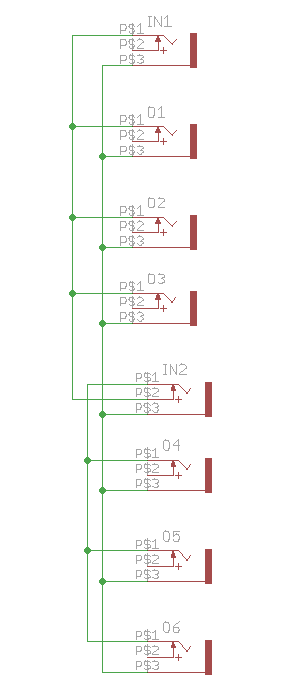
7. Ifthingsarenotworking,useamultimeteroncontinuitymodeandtestforcontinuityin
accordancewiththeschematic(allgroundsshouldhaveconnectivity,andwithnocables
inserted,thereshouldbecontinuitybetweenallsignallugs,jack5’sswitchedjackshould
havecontinuitywithinput1’ssignaljack).Thethreemostlikelyerrorsare:1)Thereisacold
solderjoint.Inspectcloselylookingforapoorsolderjoint,andreflowsolderifnecessary.2)
Ajackissomehowinsertedincorrectly.ThereisonlyonewayforalljackstofitthisPCB,so
thiswouldbehardtodo,butitispossible.Finally,ensurethatyousolderedthejackstothe
correctsideoftheboardbycomparingyourbuildwiththepicturesinthisguide.
8. ShareyourbuildonFacebookat:
https://www.facebook.com/AISynthesis1123432724366073/?fref=ts!
9. Ifyouarehavinganyissuesatall,pleasecontactusat:http://aisynthesis.com/contact/.