CreamWare MINIMAX ASB User manual

1
Owners Manual
MINIMAX ASB

2
MINIMAXASBismanufacturedbyCreamWareAudioGmbH,
Siegburg,Germany.
(C)CreamWare1998- 2005 - all rights reserved.
Thefollowingdocumentation,compiledbyCreamWareAudioGmbH(henceforth
calledCreamWare), representsthecurrentstateofthe described product.The
documentationmay beupdatedona regular basis.Anychanges which might
ensue,including those necessitatedbyupdatespecifications, are included in the
latestversion of this documentation.CreamWareisunder no obligation to notify
anyperson, organization, or institution ofsuchchangesorto make these
changespublic in anyotherway.
We must caution you that this publication could include technical inaccuracies or
typographicalerrors.
CreamWareoffersno warranty,eitherexpressedor implied, for the contentsof
thisdocumentation.Youwillfindthe warranty regulations for the productatthe
endof this documentation.
InnoeventwillCreamWarebeliableforanyloss of dataor for errorsindatause
orprocessingresultingfromtheuseofthisproductorthedocumentation.In
particular, CreamWarewillnotbe responsible for any direct or indirectdamages
(includinglostprofits,lost savings, delays or interruptions in the flow of business
activities,including but not limitedto,special,incidental,consequential,or other
similardamages)arisingoutofthe use of or inability to use this product or the
associateddocumentation, evenifCreamWareorany authorized CreamWare
representativehasbeen advised ofthepossibilityof such damages.
Theuse of registered names, trademarks, etc., in this publication does not imply,
evenin the absence of a specific statement,thatsuchnamesareexemptfrom
therelevant protective lawsandregulations (patentlaws, trademarklaws.etc.)
andtherefore free for general use.Innocase does CreamWareguarantee that
theinformation given in this documentation is freeofsuchthird-partyrights.
Neitherthis documentationnorany partthereofmaybe copied, translated,or
reducedto any electronic medium ormachineformwithout the prior written
consentfrom CreamWareAudioGmbH.
Thisproduct (and the associated documentation)isgovernedby the GTC
(GeneralTermsand Conditions) of CreamWareAudioGmbH.

3
Index
Owners Manual MINIMAX ASB
Disclaimer 02
Welcome 04
Setup and layout 05
Getting started
Making connections 08
Power adaptor 08
MIDI connection 08
Audio connection 09
Power switch 09
USB connection and drivers 09
Installation of Remote-software 10
Presets 11
The Control Panel
Controllers 12
Oscillator Bank 13
Mixer 14
Modifiers 15
Output 18
The Configuration-Strip
Match 19
Value 19
MIDI 20
Sound 20
Presets 20
Effects 21
Effectprogramms / Parameters 21
MINIMAX ASB Remote-Software
General information 24
The panel´s layout 24
Main-page 25
Add-page 25
Prefs-page 28
MIDI monitor 30
MIDI keyboard 31
Preset administration 32
Specifications
MIDI implementation table 34
Specifications 35
Warranty regulations 36
CE certification 36

4
Introduction
What’s inside the MINIMAX ASB?
Welcome
Thank you for choosing MINIMAX ASB. You will have just as
much fun with your MINIMAX ASB as we had when
developing this unique and characteristic Synthesizer. Please
read the manual thoroughly in order to fully take advantage of
the many features the MINIMAX ASB has to offer.
Introduction
One may not consider a synthesizer with three Oscillators and
noise, a mixer as well as a filter followed by amplifiers and
two envelopes, as being spectacular in sound. But we are not
just talking about any kind of synthesizer but about “the"
synthesizer that started it all.
MINIMAX ASB is a perfect emulation of one of the most
popular synthesizers ever. Its ease of use and easy to learn
sound technique made this instrument a role model for many
other synthesizers. Its sound is famous. The oscillators and
filters are extremely powerful and the envelopes extremely
quick.

5
Many soft and hardware companies have tried to copy its
features but have shattered by doing so. Its hardware
duplicate had different built-in components taking away from
its original sounding character. Most software programs
emulated only parts of the hardware such as the filter.
Significant elements like Oscillators and envelopes were for
the most part forgotten.
MINIMAX ASB is different from anything available before.
MINIMAX ASB not only emulates parts of the instrument. We
consider it as being “the” synthesizer. Today, where most
hardware components are difficult to get and software reached
the limits, MINIMAX ASB has managed to go beyond.
Within the MINIMAX ASB, we have remodelled all significant
sound elements after the original’s circuitry. In addition, a
steady cross-check with the Original was made and now offers
even identical knob positions as within the original. No
reproduction has yet been that precise. Measurements and
adjustments were only a part of the work. Beforehand there
was another problem to tackle. The original analog model
produces frequencies which when copied or emulated would
produce aliasing. Those who are familiar with aliasing know
how awful it sounds. The MINIMAXASB’s sound generation is
based on newly developed algorithms that are free of any
aliasing. The MINIMAX ASB handles even the most complex
Modulations, filter FM or Oscillator-Modulation. Moreover, the
nice thing about this, the MINIMAX ASB will always sound like
the original. Thus MINIMAX ASB tops today’s digital synthesis
technique.
Setup and Layout
Just as the original, the MINIMAX ASB has one oscillator
section with three oscillators. Oscillator 3 can also be used as
an LFO or better said FO (Frequency Oscillator). Oscillators
can be mixed with noise and an external signal within the
mixer section. This is followed by the filter and an amplifier
each using an envelope with attack, decay and sustain pro
voice. In addition to the original model, equipped the
MINIMAX ASB with an additional effects section featuring
chorus/flanger and delay.

6
The quality of the synthesis algorithms in this instrument is
remarkable. Because the oscillators use the frequency
spectrum’sfullbandwidth, moreovertonesareproduced than in
earlier algorithms. Even the saturation level in the mixer
section for internal and external signals were taken into
consideration. Saturation gives the sound more presence.
Especially the filter profits greatly from the new algorithms.
Existing filter-algorithms may have had resonance, but in
general they weren’t that exciting like the analog archetype.
Using digital filters caused high attention to avoid Aliasing
when using filter sweeps. Many filters therefore reduce the
amount of resonance or don’t open wide enough to not cross
the borderline to Aliasing (half sample frequency). Filter
sweeps with such filters have been so so, but normally were
lacking kind of vitality. The filter implemented in your
MINIMAX ASB now provides all the resonances and
distortions, you desire. Filter resonance can be fully tuned on
and sweeps can be performed withoutAliasing, even when
exceeding the half sample frequency border. This way also a
Filter FM with all the possible side chains occurring is easily
possible.
Besides that the envelopes of the MINIMAX ASB don’t need
hideawayfromtheanalog paragons. They’re not onlyfast,but
also exactly modeled like the Original’s behavior.
Although our major goal for the development of the MINIMAX
ASB has been to reach out for getting as close as possible, we
decided to also implement some of the never fulfilled dreams
of the Original. The envelopes now have an adjustable
velocity and the trigger behavior can be easily switched.
Moreover the Low-Note-Priority can be changed to Last-Note-
Priority. You will note, that there’s an extended effects section
included now, which can be switched off to receive the
Original Sound. And additionally – the Original had only one,
but beautiful voice, desperately waiting for others to join. Now
it’s all in your hands – you can choose between playing
monophonic or polyphonic – it’s up to you.

7
You will also find our adoration for the Original within the
surface. All elements have been adjusted to fit the Original’s
behavior. If you may have one of the rare sound sheets, you
can even port them now one on one – and then: save them.
And after all, you should take some time to touch the wooden
parts, this is pure nature handcrafted for this fine instrument
and using only natural materials and oil, to get that exiting
surface.
Well – as mentioned before: we made this because we loved
our work and we really hope you enjoy your MINIMAX ASB
with the same intensity, we used to create it – for you.

8
Getting started
Making Connections
Connecting the power adaptor
To connect your MINIMAX ASB with the power supply, please
use the power adaptor coming with the MINIMAX ASB.
Connect the power adaptor to your MINIMAX ASB. Before
connecting the power adaptor to the socket, make sure it is
compatible to the power supply system. Upon loss of the
power supply, a standard AC or DC 12V / 1.5 A power supply
can be used as a replacement. The connection to the
MINIMAX ASB is made with a hollow plug (5.5 mm x 2.1mm x
11.5 mm, center positive).
MIDI connections
There are two ways to play your MINIMAX ASB using MIDI:
1. Connect your MINIMAX ASB directly to a master
keyboard.
2. Connect your MINIMAX to the MIDI port found on your
computer in order to use it with a sequencer or the
MINIMAX Remote-Software.
Connect the MIDI in and out of your MINIMAX ASB with the
MIDI in and out of your keyboard or computer. The MIDI input
of the MINIMAX ASB has to be connected to the MIDI output
of your keyboard or computer and MIDI output of the
MINIMAX ASB with the MIDI input of your keyboard or
computer.
The incoming MIDI signal can also control another instrument
via MIDI thru. If your computer does not have a MIDI port, you
can use the USB connection as an alternative.

9
Audio Connections
In order to obtain sound output, you may either connect the
MINIMAX ASB stereo outputs to a mixer’s inputs, computer’s
inputs or HiFi stereo input.
You can also process an external signal
by connecting an external source to
your MINIMAX ASB input.
Power Switch
In order to operate the MINIMAX ASB please
turn the power switch on.
USB Connections and driver installation (Windows XP)
Rather than using MIDI to connect your MINIMAX ASB to a
computer, you can use the
implemented USB
interface. To utilize this
function, you need Windows
Service Pack 2.
After connecting to a
computer, windows will
automatically recognize
your MINIMAX ASB as an
audio USB instrument. No
extra drivers are required
for this device . You can
start playing right away!
After starting your
sequencer program (here:
CubaseSX), you can use
the USB audio instrument
driver as a MIDI port. In very few cases, you may encounter
that under older versions of Windows XP (before Service
Pack 2), the USB port will not show availability after
disconnecting the MINIMAX ASB. In this case, please reboot
XP. After rebooting, your USB port will show availability again.

10
Installation of the Remote-Software
To install the Remote-Software coming with the MINIMAX ASB
on your PC, please put the CD-ROM with print MINIMAX ASB
into the CD-R drive of your Computer. The Install Dialog should
then appear on your screen automatically. In case you have de-
activated the automatic Start-function of
your CD-R drive, please start the
installation by double clicking the file
„setup.exe” on the CD.
Within the first dialogue please choose
the language used within the install
procedure and then, confirm your choice
by pressing the „Next“ button.
Youwillnextsee the„Welcometo theInstallation“Dialog–please
confirm by pressing „Next“.
In the following you will find the license agreement. Please read
carefully and choose „ I accept the
license terms“ if you agree and go the
next dialog by pressing „Next“ button
then.
You can now choose the installation path by defining it within the
drop down menu „Installation path“. If you
don’t choose a dedicated path here, the
Remote-Software will be installed to
“C:\Programs\Minimax”. The required
empty space on your hard-disk is 6.7 MB.
Within “Choose Startmenu-Folder” you
can decide the directory your own.
Otherwise the directory “Minimax” will be
created and used.

11
In the following dialog you have the opportunity to check your
setting once again. If all settings are
correct, please choose install to start he
installation process.
The final dialog offers the opportunity
to open the Readme-File with actual
information about the MINIMAX ASB
and to start the Remote-Software after
installation.
Presets The Preset administration will be handled
within the sound section of the
Configuration-strip. There are 128 user and
128 factory presets. Actuate the preset
button. Use the DOWN/UP button or data
wheel to scroll through the presets. A preset
holds all parameter and effect adjustments as well as the
remote software’s “Add Page”.
You can only save presets in the User-Bank. This is the
reason why “User” will automatically be selected when
saving a preset.
12
Editing
The Control Panel
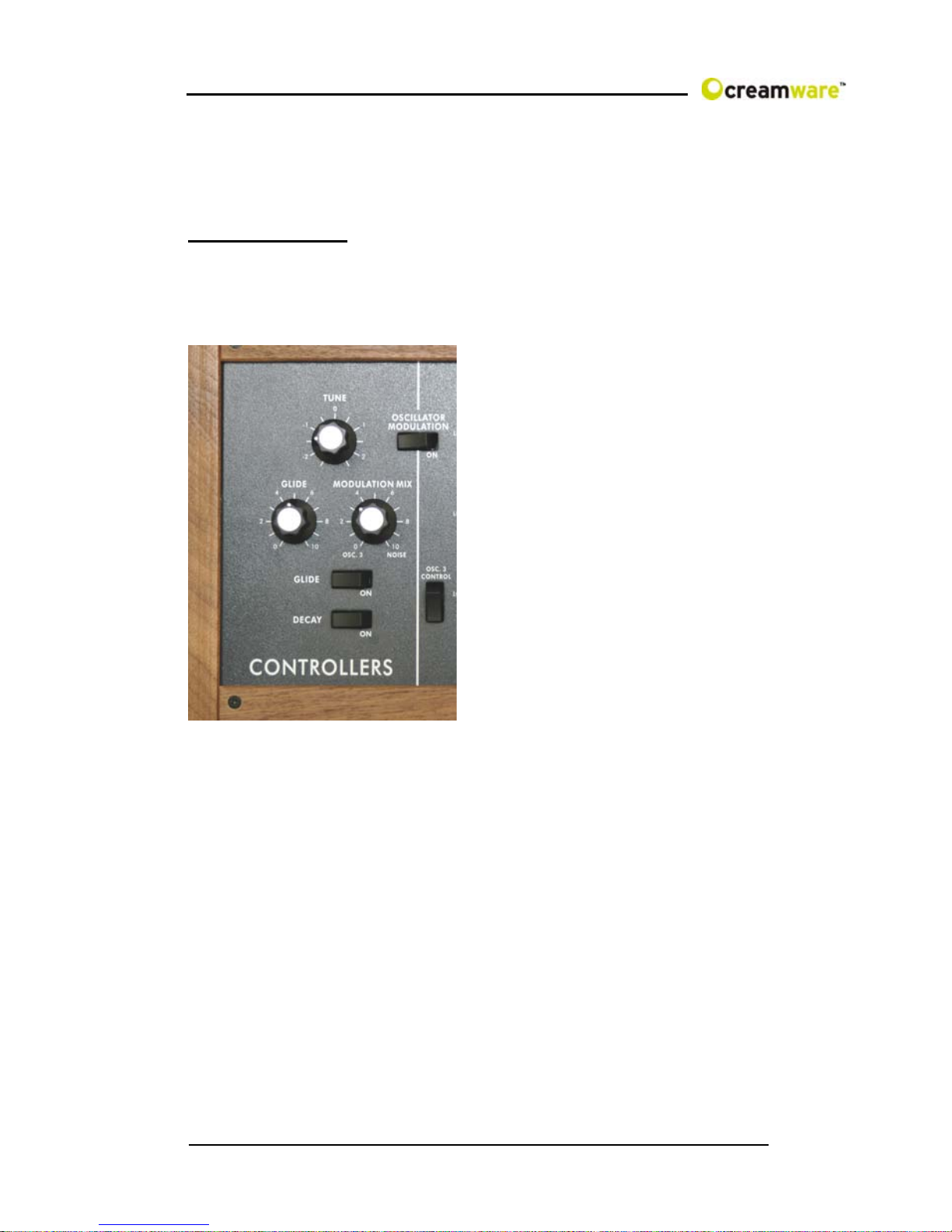
CONTROLLERS
In this section, we will take into account common operations
concerning this instrument and its modulation matrix.
Tune
This switch changes the entire
instrument’s tune by +/- 2.5 half
steps.
Glide On
This button activates the Glide
function. A played note will then
glide into the next.
Glide
When Glide is activated, you
can adjust the glide time
between the notes with the
Glide knob.
Modulation Mix
Here, you can adjust the mix between Oscillator 3 and noise.
The resulted signal serves as a modulation source for the
oscillator bank and filter. In order to hear the results, all
modulations need to be adjusted in equivalence on the
modulation’s wheel intensity .
Decay On
This switches the envelopes decay time to release. The
release time will be also modulated with the Decay knobs. If
Decay is turned off, release will be at minimum.

13
OSCILLATOR BANK
The oscillator bank has
three oscillators. It is
possiblewitheach
oscillator, to adjust its
octave range as well
as waveform.
Oscillator 2 and 3 can
further more be
detuned with the
Frequency knob.
Because oscillator 3
can also be used as a
modulation source, it is
possible to separate it
from the keyboard’s
frequency input. The
oscillator then acts as an LFO (Low Frequency Oscillator).
You can adjust its speed with Range and Frequency. A button
activates the oscillators pitch modulation. An LFO is used as a
modulation source and can control parameters such as cutoff
for example. Because oscillator 3 modulates much faster than
an LFO, it is almost incorrect to call it an LFO.
Range
You can choose the oscillator octave’s range. The adjustments
are Lo, 32, 16, 8, 4 and 2 where as the values 32’ and 16’ are
best for basses and values 8’ and 4’ best for lead sounds. If
you would like to use oscillator 3 as an LFO, then choose the
value Lo.
Waveform
You can choose the oscillator’s waveform. For each oscillator,
there is a choice of six waveforms, which are triangle, a mix
between Saw Wave and Triangle, an Ascending Saw Wave,
Square, Wide Pulse and Narrow Pulse. As a special feature,
Oscillator 3 uses a Seceding Saw Wave instead of a mix
between Triangle and Saw Wave.
14
Frequency
You can detune oscillator 2 and 3 with oscillator 1. The scale
shows the amount of detune in half tone steps with a
maximum of 9 half tone steps.
OSC 3 Control
It is possible here to separate oscillator 3 from the keyboard
(’s frequency input). Oscillator 3 acts then as sound element
with a fixed frequency, for example, as an LFO. When
oscillator 3 is used as an LFO, you can adjust its speed with
Range for coarse alterations and with Frequency for finer
alterations.
Oscillator Modulation
Here, you can activate pitch modulation for all three
oscillators. The signal, adjusted within the Modulation Mix
works as a modulation source. This can be either oscillator 3,
noise or a mixer of both. The modulation wheel and its
parameters can adjust the intensity. (Shown in the Modulation
Wheel Settings under the Remote Software)
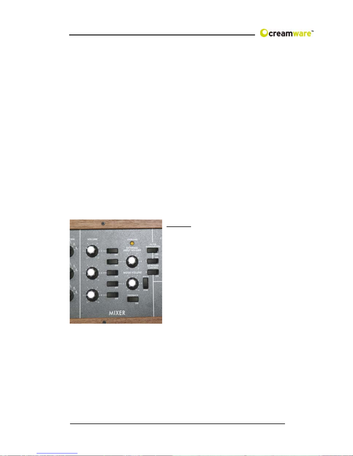
MIXER
In this section, all signals are
mixed before they go through the
Filter. The signals are oscillator 1
through, the noise generator and
an external signal. That is
altogether six sound sources
including filter oscillation, directly
produced by the filter. Every
sound source has a specified
knob to adjust the volume and an
on/off switch. It is in addition
possible if wanted or needed, to distort external signals.
Volume
Here you can adjust the volume of each oscillator.
External Input Volume
This controls the volume for external signals. In order to hear
a signal, you need to connect the MINIMAX ASB Audio-Input
with an external sound source. The view control is above the
volume slider. The louder the signal, the brighter is the light.

15
Feedback on
This function connects the synthesizer’s output to the external
input. You can use the external input amplifier to distort
incoming signals. External Input Volume controls the
amount of feedback or distortion.
Bear in Mind that an external signal source cannot be
used in this modus.
Noise Volume
Here, you can adjust the noise’s volume. If noise acts as a
modulation source, volume adjustment will not affect the
intensity of the modulation. In this case the modulation signal
will be taken as is before going through this section.
Noise White/Pink
You can choose the type of noise. Your choice will affect
modulation if noise is used as a modulation source. White
noise is constant noise throughout the whole frequency
spectrum where as Pink noise is noise only using frequencies
the human ear can perceive.
MODIFIERS
In this section, filters and amplifiers modify the signal. Both
filter and amplifier each have an envelope with attack, decay
and sustain. A switch in the controllers section sets Release to
the Decay Time.
Filter
The filter together with the envelopes define the way the
sound progresses. The filter is a 24db/Octave Low pass filter.
Frequencies under the cutoff frequency remain unchanged,
reason for the term Low pass. There is a 24db/Octave
reduction for frequencies over the cutoff frequency. With use
of DSP-oversampling the filter remains free of aliasing.
Cutoff Frequency
This is the frequency above which
the spectrum is cut. Overtones are
reduced this way. You can change
the Cutoff Frequency manually.

16
Emphasis
Emphasis describes the Resonance parameters. The
Resonance is created by routing the feedback of the Filter
Output to the Filter Input. The frequencies around the cutoff
frequency will be strengthened this way. On full Emphasis the
Filter sweeps in its own resonance and creates a sinus tone at
the chosen cutoff frequency. Therefore the Filter can be
looked upon as the sixth sound source.
Amount of Contour
Adjust the intensity of the envelope on the Filter here. Cutoff
will follow the envelope course with the adjusted intensity –
this way you can create a sound flow. Starting and End point
of the envelope course is the adjusted cutoff frequency.
Attack
This controls the attack time of the envelope, the envelopes
first segment. When setting Attack to a maximum, the
envelope increases in time. The increase ratio is defined by
amount of contour. Both Cutoff
Frequency and Amount of Contour
determine the maximum level.
Decay
This controls the envelopes second
segment. Within the Decay-Phase
the envelope falls down within the given time to the Sustain
value adjusted. When activating the decay button in the
Controllers Section, the envelope takes charge of the
release time.
Sustain
This is the third segment of the envelope. Values here sustain
the envelope after the Decay. The Sustain’s effect is
independent from Cutoff Frequency and Amount of Contour
adjustments.
Release
Finally yet importantly, Release is the fourth segment of the
envelope. It is only active when the Decay button is on. There
are no controllers for the release phase. The envelope goes
back to its minimum in the Release-Phase. The value of the
envelope is defined by cutoff. The time for the envelope
falling to its minimum is defined by Decay.

17
Filter Modulation Here you can activate additional Filter-
Modulation. The source will be the
signal defined within the Modulation-
Mix section. This can be Oscillator 3,
Noise or a mix of both. Intensity can be
adjusted by using the Modulation-
Wheel and its additional parameters.
Keyboard Control
This activates the Cutoff Keyfollow
function with two steps possible. By
activating the upper push button (1) the cutoff frequency
follows with 1/3 octave per octave on the keyboard. By
activating lower push button (2) the cutoff frequency follows
with 2/3 octave per octave on the keyboard. Activating both
push buttons will result in a full octave – cutoff then follows
the frequency plaid on the keyboard.
Loudness Contour
Together with the envelope the Amplifier defines the volume-
curve of the sound.
Attack
Attack defines the duration of the
first envelope segment. Within the
Attack Phase the envelope curve
increases within the adjusted time
to the maximum adjusted volume.
Decay
Decay describes the duration of the second envelope
segment. Within the Decay-Phase the envelope curve falls
within the adjusted time to the volume adjusted under Sustain.
If you activated the push button Decay within the Controllers
Section, the time chosen there will be taken for release of the
envelope.
Sustain
Sustain is the third segment of the envelope curve and
describes the volume, on which the envelope curve remains
after Decay.

18
Release
Release is the fourth element in influencing the envelope
curve. It is only active, if the Decay push button is switched to
“On” position. The Release-Phase can not be adjusted by a
dedicated button or knob. Within the Release-Phase the
envelope falls down to its minimum and the sound disappears.
The duration of this process can be adjusted with the Decay
knob.
OUTPUT
Velocity
The keyboard’s velocity modulates
every level of the envelope. The
Envelope varies increasingly or
decreasingly in modulation depending
on how intense or less intense the
keyboard is played. The upper knob
controls the Amplifier’s Envelope and
the lower knob, the Filter Envelop.
Volume
With the Volume setting you define the
volume of the complete instrument.
Please turn down the volume, if
distortion in polyphonic sounds should
occur.
Please note: the volume is placed before
the effects section, thus you can use the
volume knob also to measure the
effects. If you have a heavy feedback from the flanger
you can herewith avoid distortion. And most important:
the volume settings will be stored separately for every
preset.

19
The Configuration-Strip
The Configuration-Strip is used for System-Adjustments,
Preset Configurations and various Display features.
Match This display shows you all adjustable values for
every parameter of the chosen preset . Turn a
knob long enough so the LED (PRESET) in the
middle blinks. If the changed value is smaller
than the one in the Preset, then one of the three
LEDs (left) will light up. Should the value be
greater, then one the first LEDs (right) will light up. In this
respect, you can easily make out the Preset’s value.
Value
With the Data-Reel (on the left) and the
DOWN/UP buttons you can set the
parameters of the Configuration Strip,
like i.e. MIDI-Channel or Volume.
Choose between the monophonic /
polyphonic mode by pressing DOWN and UP button at the
same time (MONO/POLY). The display will show “of” for
monophonic and “on” for polyphonic mode.

20
Midi
Actuate the CHANNEL button in order to select the desired
MIDI channel with the DOWN/UP buttons or Data Wheel. If a
small vertical line appears under the channel
number, this means the instrument receives MIDI
data on all channels (Omni-Mode). Midi data will be
sent though, on the selected channel. Without the
line, the instrument receives and sends MIDI data on
the selected channel.
Midi Values: MIDI Channel 1 … 16 Omni Off
MIDI Cannel I1 … I16 Omni On (Vertical Lines)
ActivatetheCONTROLbuttonin order to select the desired
MIDI-Local-Moduswiththe DOWN/UP buttons orDataWheel.
“Local Off” is on when the display shows “of” and “Local On”
on when showed “on”. In Local Off Modus all local controllers
are set to off.
Sound
ActivatetheVOLUMEbuttontochangethevolumewiththe
DOWN/UP buttons or Data Wheel. This is
the main volume for the complete hardware
will not be saved within a preset.
Preset
Activate the PRESET button in order to
select the desired Preset with the DOWN/UP
buttons or Data Wheel.APreset withholds all adjustments,
“Add Page” parameters of the Remote Software and Effect
adjustments. Presets can only be saved in the User Bank,
reason why “USER” will automatically be selected when
saving a preset.
Table of contents
Other CreamWare Synthesizer manuals

CreamWare
CreamWare Noah Vocodizer User manual

CreamWare
CreamWare PRO-12 ASB User manual

CreamWare
CreamWare Noah Arpeggiator User manual

CreamWare
CreamWare Noah Step Sequencer User manual

CreamWare
CreamWare Noah Minimax User manual

CreamWare
CreamWare Noah Interpole User manual

CreamWare
CreamWare MINIMAX Klangbox User manual

CreamWare
CreamWare Noah Vectron Player User manual

CreamWare
CreamWare Noah Installation instructions

CreamWare
CreamWare PRO-12 ASB User manual


