AICSYS SBC-6504 User manual

SBC-6504
PICMG 1.0
Single Board Computer
User Manual
2009/11/05

SBC-6504 User Manual
Copyright
Copyright 2009, all rights reserved. This document is
copyrighted and all rights are reserved. The information in
this document is subject to change without prior notice to
make improvements to the products.
This document contains proprietary information and
protected by copyright. No part of this document may be
reproduced, copied, or translated in any form or any means
without prior written permission of the manufacturer.
All trademarks and/or registered trademarks contains in this
document are property of their respective owners.
Disclaimer
AICSYS Inc. shall not be liable for any incidental or
consequential damages resulting from the performance or
use of this product.
AICSYS Inc. does not issue a warranty of any kind, express
or implied, including without limitation implied warranties of
merchantability or fitness for a particular purpose.
The company has the right to revise the manual or include
changes in the specifications of the product described within
it at any time without notice and without obligation to notify
any person of such revision or changes.
2

SBC-6504 User Manual
Packing List
Please check the content:
SBC-6504 single board computer 1 PC
Utility CD (including user manual) 1 PC
SATA Cable 1 PC
RS232 DB9 & Printer Port DB25 Cable 1 PC
Jumpers (yellow) 5 PCS
3

SBC-6504 User Manual
Index
Chapter 1 Product Introduction................................................. 7
1.1 Product Overview.............................................................7
1.2 Product Specification........................................................8
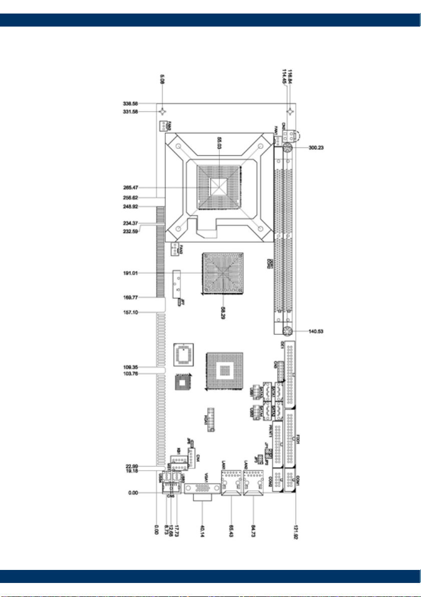
1.3 Mechanical Drawing........................................................10
Chapter 2 Hardware Installing ................................................ 11
2.1 Board Layout.................................................................11
2.2 Connector List...............................................................12
2.3 Jumper List...................................................................13
2.4 CPU Installation.............................................................14
2.5 Memory Installation .......................................................15
2.6 CMOS Setup..................................................................16
2.7 IDE Interface ................................................................17
2.8 Floppy Interface ............................................................18
2.9 SATA Interface ..............................................................19
2.10 Ethernet Interface........................................................20
2.11 Display Interface..........................................................22
2.12 USB Port.....................................................................23
2.13 Serial Port...................................................................24
2.14 Power & Fan Connectors................................................26
2.15 Printer Port .................................................................28
2.16 SMBus Connector.........................................................30
2.17 Keyboard & Mouse Ports................................................31
2.18 Front Panel Connector...................................................32
Chapter 3 System Configuration.............................................. 33
3.1 I/O Port Address Map .....................................................33
3.2 Interrupt Controller........................................................34
3.3 Watchdog Timer ............................................................35
3.4 SATA Raid Configuration..................................................37
4

SBC-6504 User Manual
Chapter 4 BIOS Setup.............................................................. 47
4.1 Entering Setup ..............................................................47
4.2 Control Keys .................................................................48
4.3 Getting Help..................................................................49
4.4 The Main Menu..............................................................49
4.5 Standard CMOS Setup Menu............................................50
4.6 Advanced BIOS Features.................................................53
4.7 Advanced Chipset Features..............................................58
4.8 Integrated Peripherals ....................................................59
4.9 Power Management Setup...............................................65
4.10 PnP/PCI Configuration Setup..........................................69
4.11 PC Health Status..........................................................72
4.12 Frequency/Voltage Control.............................................74
4.13 Load Optimized Defaults ...............................................75
4.14 Set Supervisor/User Password........................................76
4.15 Save & Exit Setup ........................................................77
4.16 Exit Without Saving......................................................78
5

SBC-6504 User Manual
(This Page is Left for Blank)
6

SBC-6504 User Manual
Chapter 1 Product Introduction
1.1 Product Overview
The SBC-6504 PICMG 1.0 full-size Single Board Computer supports
Intel® Core™ 2 Duo, Intel® Celeron® 400 Series, Intel® Pentium® 4
processor in the LGA775 Land Grid Array package or Intel® Pentium® D
processor (supports 775-Land package) at FSB 533/800 MT/s (133/200
MHz).
The board integrates chipsets Intel® 945GC and ICH7/7R (Optional) that
deliver outstanding system performance through high-bandwidth
interfaces, multiple I/O functions for interactive applications and various
embedded computing solutions. There are two 240-pin unbuffered DIMM
sockets for dual channel DDR2-400/533/667 MHz memory, maximum
memory capacity up to 2GB.
It also features Gigabit/Fast Ethernet, four serial ATA channels for total
four Serial ATA hard drives at maximum transfer rate up to 300MB/sec,
and six USB 2.0 compliant interfaces.
7

SBC-6504 User Manual
1.2 Product Specification
General Specification
Form Factor PICMG 1.0 full-size single board computer
CPU Intel® Core 2 Duo, Celeron® 400 series ,
Pentium® 4 processor and Pentium® D processor
(supports 775-Land package)
Front Side Bus 533/800 MT/s (133/200 MHz)
Memory Two 240-pin unbuffered DDR2 DIMM sockets
Maximum to 2GB DDR2 400/533/667 MHz
Chipset Intel® 945GC & ICH7/ICH7R
BIOS Phoenix-Award BIOS
8Mbit FWH Flash, DMI, Plug and Play
Watchdog
Timer
1~255 seconds; up to 255 levels
Multiple I/O Ports
Chipset Intel ICH7 integrated with Winbond W83627HG
Enhanced IDE 1 x 40-pin IDE supports ATA100 up to 2 devices
SATA 4 x SATA ports support 300MB/s transfer rate
Optional SATA RAID 0/1/5/10 by ICH7R
Serial Port 1 x RS232 & 1 x jumper selectable
RS232/422/485 serial ports
Hardware
monitor
System temperature, voltage, fan speed, auto
throttling control when CPU overheat
Floppy 1 x 34-pin FDD port, up to 2 devices
USB Six USB ports with fuse protection and complies
with USB Spec. Rev. 2.0
Keyboard/Mouse 1 x internal PS/2 keyboard & mouse port
8

SBC-6504 User Manual
Display
Graphic
Engine
Intel 945GC integrated GMA (Graphic Media
Accelerator) 950
Frame Buffer Up to 224MB shard with system memory
Display Type VGA D-sub 15-pin output
Ethernet
Controller Realtek RTL8111B Gigabit Ethernet Controllers
Speed 10/100/1000Mbps
Power & Environment
Power
Requirement
Standard ATX power from backplane
Dimension 338(L) x 122(H)mm
Temperature Operating temperature: 0°C ~ 60°C
Humidity 0 ~ 90% relative humidity, no condensing
9

SBC-6504 User Manual
1.3 Mechanical Drawing
10

SBC-6504 User Manual
Chapter 2 Hardware Installing
2.1 Board Layout
LAN1 VGA1
LAN2 USB3/4
COM1
COM2 MS1
CN7 CN6 CN4 KB1
PRINT1
FDD1
SATA4
SATA2 USB2
USB1
SATA1
SATA3
IDE1
CN3
DDR2
DDR1
FAN2
FAN1
CN2
FAN3
CN1
11

SBC-6504 User Manual
2.2 Connector List
Connector Description
CN1 SM BUS Connector
CN7 LAN2 Link/Active & Speed LED Connector
CN2 ATX 4 Pin 12V In
CN3 Front Panel Connector
CN4 ACPI Connector
CN5 PS/2 KB/MS Connector (Optional)
IDE1 Parallel IDE Connector
FDD1 Floppy Connector
PRINT1 Printer Port Connector
COM1 Serial Port1 Connector
COM2 Serial Port2 Connector
USB1 USB Port5/6 Connector
USB2 USB Port3/4 Connector
USB3/4 USB Port1/2 Connector
CN6 LAN1 Link/Active & Speed LED Connector
LAN1 LAN1 Connector
LAN2 LAN2 Connector
VGA1 VGA Connector
DDR1/2 DDRII Long-DIMM Sockets
FAN1 System FAN Connector 1
FAN2 CPU FAN Connector
FAN3 System FAN Connector 2
KB1 Internal PS/2 Keyboard Connector
MS1 Internal PS/2 Mouse Connector
SATA1~4 Serial ATA Port Connectors
12

SBC-6504 User Manual
2.3 Jumper List
Jumper Default Setting
COM2 Pin 1: DCDJP1 COM2 Mode Select
COM2 Pin 8: RI
Short 3-5
Short 4-6
COM2 Pin 1: DCDJP2 COM2 Mode Select
COM2 Pin 8: RI
Short 3-5
Short 4-6
JP3 COM2 Mode Select : RS-232 Short 1-2
JP6 ATX Auto Power On/Off : Disable Short 1-2
JP7 Clear CMOS Setting : Normal Short 1-2
JP1
JP2
JP3 JP6
JP7
13

SBC-6504 User Manual
2.4 CPU Installation
The board supports Intel Desktop Processors as:
Socket Type LGA775
Front Side Bus 533/800MHz
Generation Intel® Core 2 Duo, Celeron® 400 series ,
Pentium® 4 processor and Pentium® D
processor
Please follow the installation steps:
Check point
1. Lift this bar
2. Uncover this plate 3. Place the CPU on the
to
p
of the
p
ins
3. Cover this plate
4. Lock this bar
Notice: Please place the CPU on the pins tenderly to avoid bending the pins
14

SBC-6504 User Manual
2.5 Memory Installation
The board supports four 240-pin DDR2 DIMM memory sockets with
maximum memory capacity up to 2GB.
Please follow steps below to install the memory modules:
Push down latches on each side of the DIMM socket.
Align the memory module with the socket that notches of memory
module must match the socket keys for a correct installation.
Install the memory module into the socket and push it firmly down until
it is fully seated. The socket latches are levered upwards and clipped on
to the edges of the DIMM.
Install any remaining DIMM modules.
15

SBC-6504 User Manual
2.6 CMOS Setup
The board’s data of CMOS can be setting in BIOS. If the board refuses to boot due
to inappropriate CMOS settings, here is how to proceed to clear (reset) the CMOS
to its default values.
Jumper: JP7
Type: Onboard 3-pin jumper
JP7 Mode
1-2 Normal Operation S
2-3 Clear CMO
Default setting
1 3
16

SBC-6504 User Manual
2.7 IDE Interface
IDE1 is a 40-pin IDE interface connector for standard 3.5” IDE device.
Pin Signal Pin Signal Pin Signal
1 Reset # 2 GND 3 Data 7
4 Data 8 5 Data 6 6 Data 9
7 Data 5 8 Data 10 9 Data 4
10 Data 11 11 Data 3 12 Data 12
13 Data 2 14 Data 13 15 Data 1
16 Data 14 17 Data 0 18 Data 15
19 GND 20 NC 21 DREG#
22 GND 23 IOW # 24 GND
25 IOR # 26 GND 27 IOCHRDY
28 CSEL 29 DACK# 30 GND
31 Interrupt 32 NC 33 SA1
34 PDIAG# 35 SA0 36 SA2
37 HDC CS0 # 38 HDC CSI # 39 HDD Active #
40 GND
1
40
17

SBC-6504 User Manual
2.8 Floppy Interface
The board provides a 34-pin header type connector, FDD1, supporting up to two
floppy drives. The floppy drives may be any one of the following types: 5.25"
360KB/1.2MB and 3.5" 720KB/1.44MB/2.88MB.
Pin
Signal Pin
Signal Pin
Signal
1 GND 2 Drive Density Select 3 GND
4 No connector 5 GND 6 No connector
7 GND 8 Index# 9 GND
10 Motor enable A# 11 GND 12 No connector
13 GND 14 Drive select A# 15 GND
16 No connector 17 GND 18 Direction#
19 GND 20 STEP# 21 GND
22 Write data# 23 GND 24 Write gate#
25 GND 26 Track 0 # 27 GND
28 Write protect# 29 No connector 30 Read data#
31 GND 32 Head selection# 33 No connector
34 Disk change#
1
34
18

SBC-6504 User Manual
2.9 SATA Interface
These SATA connectors are for high-speed SATA interface ports and they can be
connected to hard disk devices.
Pin Signal
1 GND
2 SATA_TX+
3 SATA_TX-
4 GND
5 SATA_RX-
6 SATA_RX+
7 GND
1 7
19

SBC-6504 User Manual
2.10 Ethernet Interface
The board is equipped with two high performance Plug and Play Ethernet interface
fully compliant with the IEEE 802.3 standard. To connect the board to 10-Base-T,
100-Base-T or 1000 Base-T hub, just plug one end of cable to the Ethernet
connector and connect the other end (phone jack) to a 10-Base-T, 100-Base-T or
1000 Base-T hub.
Pin Signal
1 RJ-1(For 1000 base T-Only)
2 RJ-1(For 1000 base T-Only)
3 Rx- (Data reception negative)
4 RJ-1(For 1000 base T-Only)
5 RJ-1(For 1000 base T-Only)
6 Rx+(Data reception positive)
7 Tx- (Data transmission negative)
8 Tx+ (Data transmission positive)
A Active LED
B 100 LAN LED(Green)/
1000 LAN LED(Orange)
20
Table of contents