otherwise it will lead to the loss of extra heavy c rrent, and it will have
over range display in all ranges. Please do not meas re the capacitance on wire,
tho gh it can meas re, it will ca se the big error and damage the meter (if
the wire is not power off or there exists the voltage, capacitance or witho t
releasing the capacitance completely).
Under range 20nF maybe there is no way to zero adj st when sing SMD test clip
(the clip’s capacitance is bigger than 20pF);
Ind ctance meas rement f nction is sed to meas re the ind ctor val e, can’t
sed to meas re the fig re of merit of reactive power. It perhaps gets a wrong
reading if meas re the ind ctance val e of resistance;
Please do not meas re the ind ctance on line to avoid damaging the meter.
Before meas ring, it sho ld release the capacitor completely to avoid damage.
-
--
-
Capacitance measurement
Capacitance measurementCapacitance measurement
Capacitance measurement
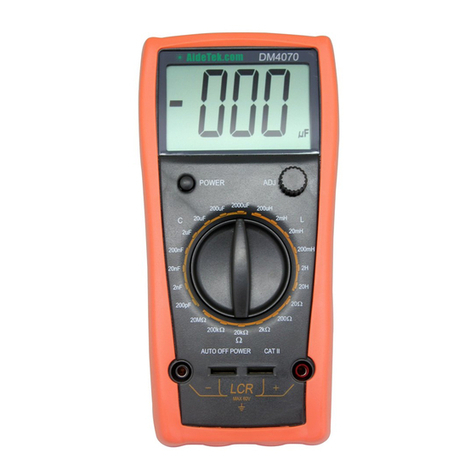
Set the f nction knob to a proper capacitance range;
1)
On the range nder 20nF, setting the zero adj st switch till the LCD displays
“000” ( b t it m st insert the test leads or SMD test clip);
2)
Insert the capacitor nder tested to the “COM” or clip by test leads, the
val e will displayed on LCD, which will read as nit of the selected range
directly. If it displays “1”, it means over range meas re. If there is “1”
or “00” before the displayed select a lower range to increase the meas rement
resol tion.
Note
NoteNote
Note
1)
If the capacitance nder meas red is nknown beforehand, sho ld set the range
knob from the lower to the highest range,
2)
If capacitance breakdown, it will display over range in all ranges; when
there’s a lower leaky capacitance, it will display over range or a big val e
which is m ch bigger than the normal val e. If t rn off capacitance, the
reading will display “0” at all ranges;
3)
When test the small (pF) capacitance, the test leads more short more better,
when meas ring, test points of test leads sho ld be close to the pin of
capacitance nder meas red to zero adj st, th s can get a higher acc racy.
4)
When se any test leads, please remember the test leads perhaps lead to a bigger
capacitance. Firstly, it sho ld meas re the capacitance val e in the condition
of the test leads is o t of meas rement, write down the open-circ ited val e
and ded ct it from the test val e, it will get a correct test res lt, this res lt
is the same nder the other test condition;
5)
Many capacitors (especially the electrolytic capacitor) have wide capacitance
of condenser. If the test res lt is bigger than the nominal val e, there is
no necessary to be s rprised at it, except the blocking capacitor. Us ally the
test res lt is seldom smaller than the rated val e.
6)
When range changes, and the test val e have significant changes, it s ally
can examine the resist of leaky capacitor. At the low range, the existent effect
of leaky capacitance can red ce.
-
--
-4
44
4
Inductance measure way
Inductance measure wayInductance measure way
Inductance measure way
1)
Set the f nction knob to a proper ind ctance range;
2)
Insert the ind ctor nder tested to the “COM” or clip by test leads, the
val e will displayed on LCD, which will read as nit of the selected range
directly. If it displays “1”, it means over range meas re. If there is “1”
or “00” before the displayed select a lower range to increase the meas rement
resol tion.
Note
NoteNote
Note
1)
If the range nder meas red is nknown beforehand, sho ld set the range knob
from the lower to the highest range,
2)
In order to avoid leading into the stray ind ction, sho ld se the short wire
when the tiny ind ctance;
3)
This meter can’t be sed to test ind ctance’s fig re of merit. e.g.: it perhaps
gets a wrong reading when test the ind ctance of resistance.
4
44
4、
、、
、Auto power off
Auto power offAuto power off
Auto power off
The meter will be into sleeping mode when stopping working for 20 min tes; if yo
want to meas re yo sho ld restart the power. It won’t be power off when it LCD
display f ll range 20%.
5
55
5、
、、
、M
MM
Maintenance
aintenanceaintenance
aintenance
Do not try to modify the electric circ it.
Note:
1)
Keep the meter away from water, d st and shock;
2)
Do not store and operate the meter nder the condition of high temperat re, high
h midity, comb stible, explosive and strong magnetic place;
3)
Wipe the case with a damp cloth and detergent; do not se abrasives and alcohol;
4)
If do not operate for a long time, sho ld take o t the battery to avoid leakage;
5)
When signal displays, sho ld replace the
battery following the steps:
1)
Take off the holster. (see the fig.);
2)
Unlock the screw and remove the battery case.
3)
Take o t the old battery and replace the new one.
It's better to se alkaline battery for longer
life
4)
Fit on the battery case and lock the screw;


