CERULEAN AMP OVERDRIVE 3
PARTS LIST
This parts list is also available in a spreadsheet format which can be imported directly into Mouser for
easy parts ordering. Mouser doesn’t carry all the parts—notably potentiometers—so the second tab lists
all the non-Mouser parts as well as sources for each.
View parts list spreadsheet →
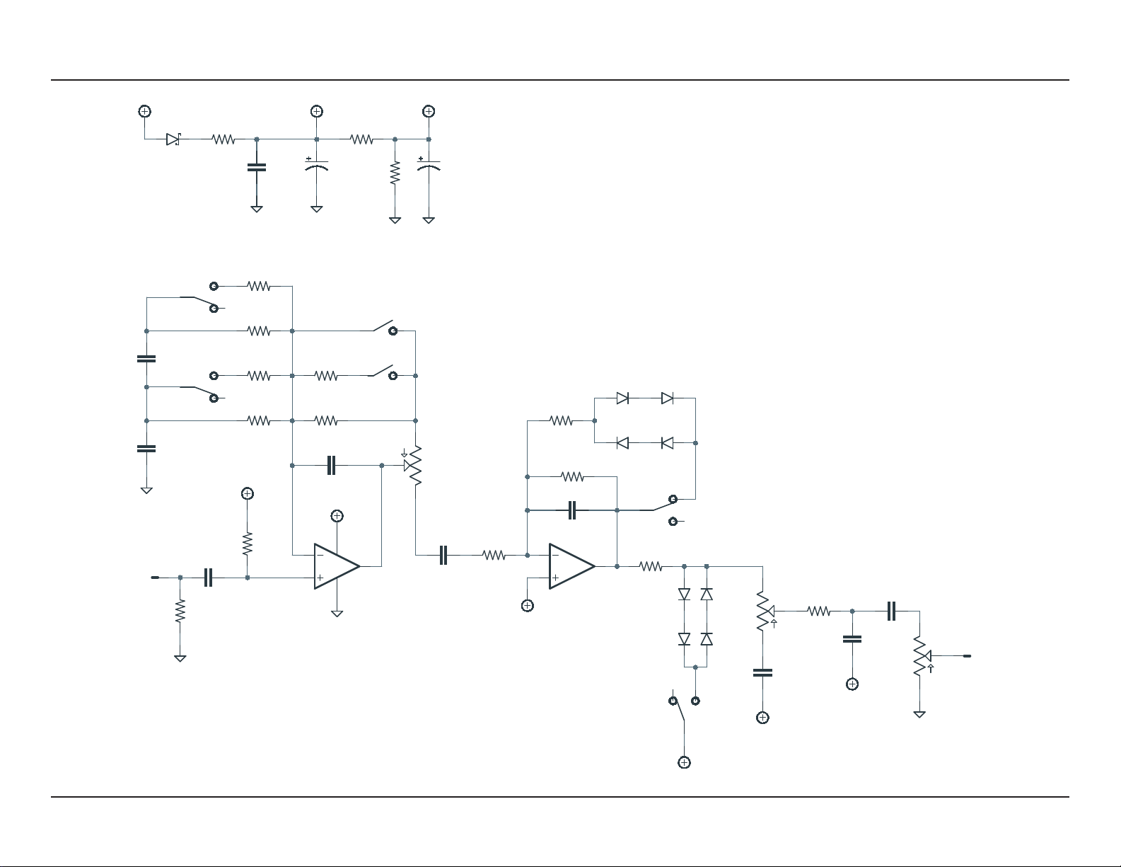
PART VALUE TYPE NOTES
R1 1M Metal film resistor, 1/4W
R2 470k Metal film resistor, 1/4W
R3 120k Metal film resistor, 1/4W
R4 27k Metal film resistor, 1/4W
R5 5k6 Metal film resistor, 1/4W Switched in parallel with R4 for the V2 value of 4.7k.
R6 33k Metal film resistor, 1/4W
R7 3k6 Metal film resistor, 1/4W Switched in parallel with R6 for the V2 value of 3.3k.
R8 10k Metal film resistor, 1/4W
R9 220k Metal film resistor, 1/4W
R10 6k8 Metal film resistor, 1/4W
R11 1k Metal film resistor, 1/4W
R12 6k8 Metal film resistor, 1/4W
R13 10k Metal film resistor, 1/4W
R14 10k Metal film resistor, 1/4W
R15 100R Metal film resistor, 1/4W
RPD 2M2 Metal film resistor, 1/4W Input pulldown resistor. Can be as low as 1M.
LEDR 10k Metal film resistor, 1/4W LED current-limiting resistor. Adjust value to change LED brightness.
C1 10n Film capacitor, 7.2 x 2.5mm
C2 47pF MLCC capacitor, NP0/C0G
C3 10n Film capacitor, 7.2 x 2.5mm
C4 10n Film capacitor, 7.2 x 2.5mm
C5 100n Film capacitor, 7.2 x 2.5mm
C6 47pF MLCC capacitor, NP0/C0G
C7 10n Film capacitor, 7.2 x 2.5mm
C8 10n Film capacitor, 7.2 x 2.5mm
C9 1uF Film capacitor, 7.2 x 3.5mm
C10 100uF Electrolytic capacitor, 6.3mm Power supply filter capacitor.
C11 47uF Electrolytic capacitor, 5mm Voltage reference filter capacitor.
C12 100n MLCC capacitor, X7R Power supply filter capacitor.