manuals.online logo
Brands
  1. Home
  2. •
  3. Brands
  4. •
  5. aion
  6. •
  7. Music Equipment
  8. •
  9. aion MAELSTROM User manual

aion MAELSTROM User manual

MAELSTROM BASS DRIVE 1
PROJECT NAME
MAELSTROM
BASED ON
EFFECT TYPE
PROJECT SUMMARY
DOCUMENT VERSION
Darkglass®Microtubes B3K
A CMOS-flavored bass overdrive with tones spanning across decades, from vintage warmth to modern
bite and aggression.
Bass overdrive / distortion 1.0.0 (2021-11-12)
BUILD DIFFICULTY
Intermediate
Actual size is 2.3” x 2.61” (main board) and 1.78” x 0.86” (bypass board).
MAELSTROM BASS DRIVE 2
TABLE OF CONTENTS
1Project Overview 8Drill Template
2Introduction & Usage 9Enclosure Layout
3-5 Parts List 10 Wiring Diagram
6Build Notes 11 Licensing
7Schematic 11 Document Revisions
INTRODUCTION
The Maelstrom Bass Drive is based on the Darkglass® Microtubes B3K, a CMOS-based drive circuit,
with some additional tweaks adapted from the Vintage Microtubes.
The B3K started life as the Microtubes 2K, which was originally posted to the DIYStompboxes forum by
Douglas Castro in 2008. After finishing university, he moved from Chile to Finland in 2010 and started
Darkglass Electronics as a commercial entity.
During this time, he continued to work on the design, and the updated Microtubes B3K became
Darkglass’s first product. While the original 2K was not described as a bass drive, the B3K and all
subsequent Darkglass products have been designed primarily for bass players and marketed as such.
As the name implies, the original Microtubes 2K was inspired by the EHX Hot Tubes from 1979 as well
as some other CMOS-based designs in the DIY community. However, by the time it had evolved into the
B3K, it really bore no resemblance to any other circuits. A single CMOS stage is used for the clipping
tone, contrasting with the cascaded inverters used by other similar circuits.
The Vintage Microtubes followed in early 2013. It’s essentially the same circuit as the B3K, but it
removes the two toggle switches and adds a new control called “Era”.
The Maelstrom is a direct adaptation of the Microtubes B3K, with the Era control ported over from the
Vintage Microtubes. With the Era control turned down, it’s identical to the standard B3K. You can also
make some more parts substitutions to build it to full Vintage Microtubes specs if you’d like.
USAGE
The Maelstrom has six controls:
• Drive controls the amount of gain from the op-amp that is fed through the CMOS inverter stage.
• Era filters the tone after the clipping stage. On the low end, it’s warm with a lot of midrange, and as
it’s turned up it adds more treble and scoops the midrange somewhat.
• Level sets the overall output of the drive signal.
• Blend pans between the buffered clean signal and the drive signal.
• Attack (toggle) selects between three different treble modes prior to the op-amp gain stage: Boost,
Flat or Cut.
• Grunt (toggle) selects between three different bass levels between the op-amp boost and the
CMOS clipping stages.
MAELSTROM BASS DRIVE 3
PARTS LIST
This parts list is also available in a spreadsheet format which can be imported directly into Mouser for
easy parts ordering. Mouser doesn’t carry all the parts—notably potentiometers—so the second tab lists
all the non-Mouser parts as well as sources for each.
View parts list spreadsheet →
PART VALUE TYPE NOTES
R1 10k Metal film resistor, 1/4W
R2 1M Metal film resistor, 1/4W
R3 100k Metal film resistor, 1/4W
R4 1M Metal film resistor, 1/4W
R5 3k3 Metal film resistor, 1/4W
R6 1M Metal film resistor, 1/4W
R7 1M Metal film resistor, 1/4W
R8 200k Metal film resistor, 1/4W 261k in Vintage Microtubes.
R9 6k8 Metal film resistor, 1/4W
R10 22k Metal film resistor, 1/4W
R11 470k Metal film resistor, 1/4W
R12 470k Metal film resistor, 1/4W
R13 1M Metal film resistor, 1/4W
R14 330k Metal film resistor, 1/4W 220k in Vintage Microtubes.
R15 3k3 Metal film resistor, 1/4W 3k3 + 220n in Vintage Microtubes. See build notes.
R16 6k8 Metal film resistor, 1/4W
R17 470k Metal film resistor, 1/4W 330k in Vintage Microtubes.
R18 10k Metal film resistor, 1/4W
R19 1M Metal film resistor, 1/4W
R20 100k Metal film resistor, 1/4W
R21 33k Metal film resistor, 1/4W 10k in Vintage Microtubes.
R22 10k Metal film resistor, 1/4W
R23 22k Metal film resistor, 1/4W
R24 22k Metal film resistor, 1/4W
R25 47k Metal film resistor, 1/4W 100k in Vintage Microtubes.
R26 1k Metal film resistor, 1/4W
R27 100k Metal film resistor, 1/4W
R28 10k Metal film resistor, 1/4W
R29 10k Metal film resistor, 1/4W
R30 100R Metal film resistor, 1/4W
RPD 1M Metal film resistor, 1/4W Input pulldown resistor.
LEDR 4k7 Metal film resistor, 1/4W LED current-limiting resistor. Adjust value to change LED brightness.
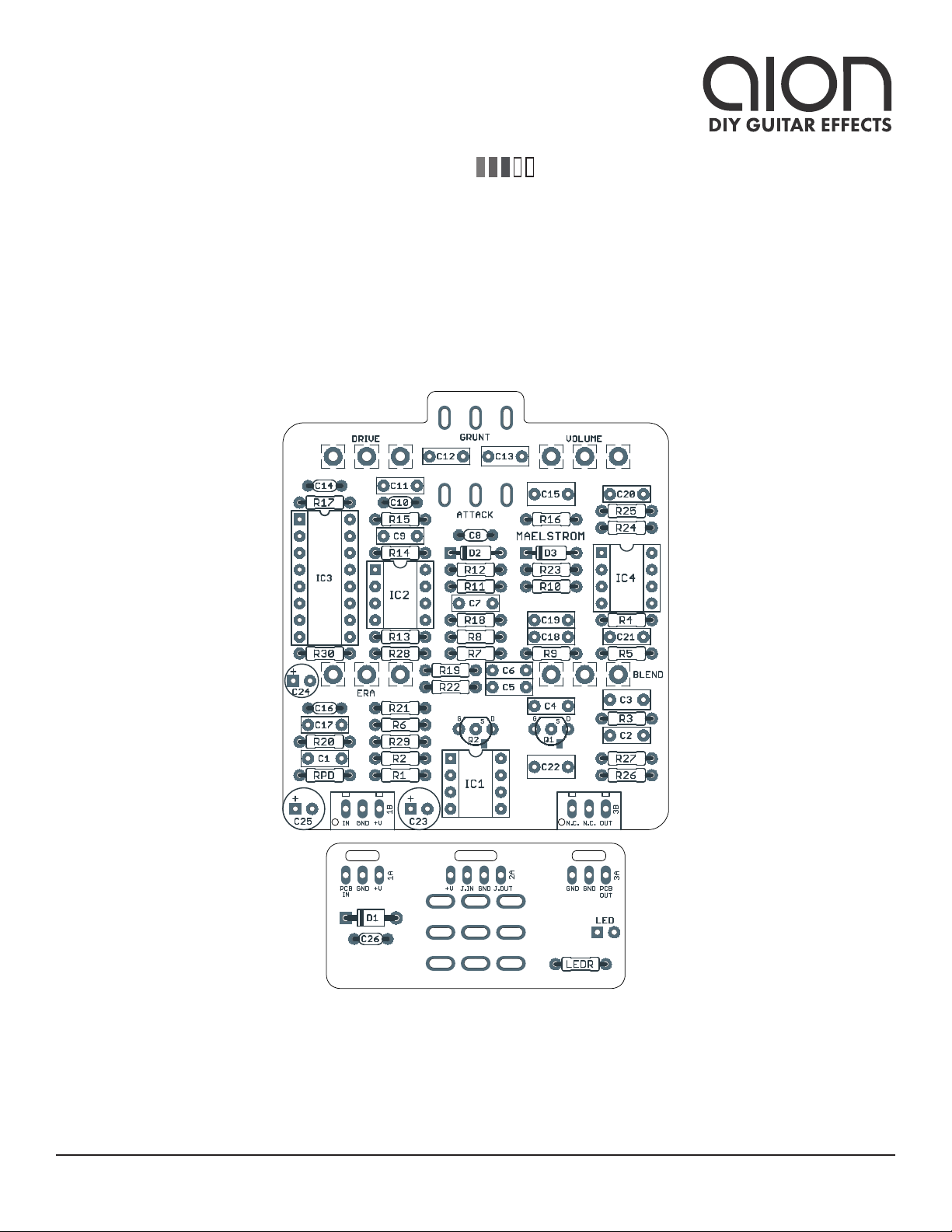
MAELSTROM BASS DRIVE 4
PARTS LIST, CONT.
PART VALUE TYPE NOTES
C1 100n Film capacitor, 7.2 x 2.5mm
C2 1n Film capacitor, 7.2 x 2.5mm 22n in Vintage Microtubes.
C3 220n Film capacitor, 7.2 x 2.5mm
C4 22n Film capacitor, 7.2 x 2.5mm
C5 22n Film capacitor, 7.2 x 2.5mm
C6 22n Film capacitor, 7.2 x 2.5mm
C7 22n Film capacitor, 7.2 x 2.5mm
C8 220pF MLCC capacitor, NP0/C0G
C9 100n Film capacitor, 7.2 x 2.5mm
C10 22pF MLCC capacitor, NP0/C0G 220pF in Vintage Microtubes.
C11 4n7 Film capacitor, 7.2 x 2.5mm
C12 22n Film capacitor, 7.2 x 2.5mm
C13 220n Film capacitor, 7.2 x 2.5mm
C14 22pF MLCC capacitor, NP0/C0G 220pF in Vintage Microtubes.
C15 1uF Film capacitor, 7.2 x 3.5mm
C16 680pF MLCC capacitor, NP0/C0G 1n in Vintage Microtubes.
C17 22n Film capacitor, 7.2 x 2.5mm 4n7 in Vintage Microtubes.
C18 2n2 Film capacitor, 7.2 x 2.5mm 1n in Vintage Microtubes.
C19 2n2 Film capacitor, 7.2 x 2.5mm 1n in Vintage Microtubes.
C20 2n2 Film capacitor, 7.2 x 2.5mm
C21 1n Film capacitor, 7.2 x 2.5mm
C22 1uF Film capacitor, 7.2 x 3.5mm
C23 100uF Electrolytic capacitor, 6.3mm Reference voltage filter capacitor.
C24 100uF Electrolytic capacitor, 6.3mm Power supply filter capacitor.
C25 220uF Electrolytic capacitor, 6.3mm Power supply filter capacitor.
C26 100n MLCC capacitor, X7R Power supply filter capacitor.
D1 1N5817 Schottky diode, DO-41
D2 1N914 Fast-switching diode, DO-35
D3 1N914 Fast-switching diode, DO-35
Q1 MMBFJ201 JFET, N-channel, SOT-23 SMD version of the J201.
Q2 MMBFJ201 JFET, N-channel, SOT-23 SMD version of the J201.
IC1 TL072 Operational amplifier, DIP8
IC1-S DIP-8 socket IC socket, DIP-8
IC2 TL072 Operational amplifier, DIP8
IC2-S DIP-8 socket IC socket, DIP-8
IC3 CD4049UBE CMOS hex inverting buffer, DIP16
IC3-S DIP-16 socket IC socket, DIP-16
MAELSTROM BASS DRIVE 5
PARTS LIST, CONT.
PART VALUE TYPE NOTES
IC4 TL072 Operational amplifier, DIP8
IC4-S DIP-8 socket IC socket, DIP-8
DRIVE 100kC 16mm right-angle PCB mount pot
ERA 100kB 16mm right-angle PCB mount pot
BLEND 100kB 16mm right-angle PCB mount pot
VOL. 100kA 16mm right-angle PCB mount pot
ATTACK SPDT cntr off Toggle switch, SPDT on-off-on
GRUNT SPDT cntr off Toggle switch, SPDT on-off-on
LED 5mm LED, 5mm, red diffused
IN 1/4" mono 1/4" phone jack, closed frame Switchcraft 111X or equivalent.
OUT 1/4" mono 1/4" phone jack, closed frame Switchcraft 111X or equivalent.
DC 2.1mm DC jack, 2.1mm panel mount Mouser 163-4302-E or equivalent.
FSW 3PDT Stomp switch, 3PDT
ENC 125B Enclosure, die-cast aluminum Can also use a Hammond 1590N1.
MAELSTROM BASS DRIVE 6
BUILD NOTES
Using SMD JFETs
The J201 JFET is no longer available in through-hole format. This PCB uses a hybrid through-hole/
SMD outline for each JFET. An extra “G” (gate) pad is included to accommodate surface-mount devices
without the need for adapters. SMD JFETs should be oriented as follows:
All surface-mount JFETs use the same pinout, so this configuration will fit any type that we’re aware of.
However, always check the datasheet if you’re uncertain—they’re difficult to desolder.
J201 adapters
Many DIY builders are intimidated by the small size of surface-mount parts. Aion FX offers pre-soldered
J201s on adapters so they can easily be used as through-hole parts.
Vintage Microtubes specifications
The Vintage Microtubes uses an almost identical circuit to the B3K, but with several parts substitutions
to give it more of a vintage flavor.
The only other addition is a 220n capacitor in series with R15. The Maelstrom PCB does not include
space for this capacitor. It can be omitted entirely (the unit will have slightly more bass available). Or,
you can “tent” it with the resistor by putting one leg of the capacitor in one pad of R15, one leg of the
resistor in the other pad, and then soldering the leads together above the PCB.
In addition, the VMT hardwires the Attack switch in treble boost mode (left toggle position) and the
Grunt switch in the highest-bass mode (right toggle position). It’s recommended to include the switches
in this build and just be aware of the “vintage” positions.
Note: The Vintage Microtubes also uses 6.65k resistors for R9 and R16 instead of 6.8k. This is almost
certainly just due to manufacturing convenience since the unit is fully SMD and many brands of
precision resistors aren’t available in E12 or E24 values. It’s recommended to stick with 6.8k in these
two positions.
PART NEW VALUE
R8 261k
R14 220k
R15 see note below
R17 330k
R21 10k
PART NEW VALUE
R25 100k
C2 22n
C10 220pF
C14 220pF
PART NEW VALUE
C16 1n
C17 4n7
C18 1n
C19 1n
SCHEMATIC
MAELSTROM BASS DRIVE 7
IN
OUT
1N5817
220uF
100kA
100kC
100kB
+9V
100n
GND
1M
GND
100n
10k
1M
TL072P
TL072P
GND
VA
10k10k
GND
VA
100R
100uF
GND
VB
VC
100uF
GND
VB
1n
100k
1M
GND
J201
3k3
220n
GND GND
J201
22n
1M1M
VA
VA
GND
200k
22n
6k8
22n
22k
GND GND
22n
470k
220pF
GND
470k
GND
100n
1M
VB
TL072P
TL072P
VA
GND
330k
22pF
3k3
VB
4n7
22n
220n
6k8
1N9141N914
GND
VA
CD4049UBE
470k
22pF
1uF
10k
1M
VB
100k 33k
680pF
22n
GND
VC
GND
CD4049UBE
CD4049UBE
CD4049UBE
CD4049UBE
CD4049UBE
10k
22k TL072P
TL072P
GND
VA
2n2
2n2
GND
22k
47k
2n2
1n
GND
VB
1uF
1k
100k
GND
VA
100kB
D1
C25
VOLUME
1
2
3
1
2
3
DRIVE
BLEND
1
2
3
C26
RPD
2
3
1
ATTACK
2
3
1
GRUNT
C1
R1
R2
IC1A
2
3
1
84
6
5
7
IC1B
R28R29
R30
C23
C24
C2
R3
R4
Q1
R5
C3
Q2
C4
R6R7
R8
C5
R9
C6
R10
C7
R11
C8
R12
C9
R13
2
3
1
IC2A
84
6
5
7
IC2B
R14
C10
R15
C11
C12
C13
R16
D2D3
IC3A
23
R17
C14
C15
R18
R19
R20 R21
C16
C17
8 1
IC3B
45
IC3C
67
IC3D
109
IC3E
1211
IC3F
1514
R22
R23
2
3
1
IC4A
6
5
7
IC4B
84
C18
C19
R24
R25
C20
C21
C22
R26
R27
ERA
1
2
3
GND
MAELSTROM BASS DRIVE 8
DRILL TEMPLATE
Cut out this drill template, fold the edges and tape it to the enclosure. Before drilling, it’s recommended
to first use a center punch for each of the holes to help guide the drill bit.
Ensure that this template is printed at 100% or “Actual Size”. You can double-check this by measuring
the scale on the printed page.
Top jack layout assumes the use of closed-frame jacks like the Switchcraft 111X. If you’d rather use
open-frame jacks, please refer to the Open-Frame Jack Drill Template for the top side.
LED hole drill size assumes the use of a 5mm LED bezel, available from several parts suppliers. Adjust
size accordingly if using something different, such as a 3mm bezel, a plastic bezel, or just a plain LED.
ø3/8” ø1/2”
0.385”
0.625” 0.625”
x: -0.65, y: +1.71 x: +0.65, y: +1.71
ø9/32” ø9/32”
x: -0.65, y: +0.41
ø9/32”
x: +0.65, y: +0.41
ø9/32”
x: 0, y: -1.775
ø15/32”
x: -0.775, y: -1.775
ø5/16”
CENTER (0,0)
ø3/8”
125B
OUT
VOLUME
GRUNT
ATTACK
DRIVE
BLEND ERA
FOOTSWITCHLED
DC IN
x: 0, y: +0.83
ø1/4”
x: 0, y: +1.29
ø1/4”
0 1 2
CM
0 1
INCH
MAELSTROM BASS DRIVE 9
ENCLOSURE LAYOUT
Enclosure is shown without jacks. See next page for jack layout and wiring.
125B
MAELSTROM BASS DRIVE 10
WIRING DIAGRAM
125B
IN +VGND NC NC OUT
PCB
IN
GND +V +V JACK GND JACK
OUTIN
GND GND PCB
OUT
MAELSTROM BASS DRIVE 11
LICENSE & USAGE
No direct support is offered for these projects beyond the provided documentation. It’s assumed
that you have at least some experience building pedals before starting one of these. Replacements and
refunds cannotbe offered unless it can be shown that the circuit or documentation are in error.
All of these circuits have been tested in good faith in their base configurations. However, not all the
modifications or variations have necessarily been tested. These are offered only as suggestions based
on the experience and opinions of others.
Projects may be used for commercial endeavors in any quantity unless specifically noted. No
attribution is necessary, though a link back is always greatly appreciated. The only usage restrictions
are that (1) you cannot resell the PCB as part of a kit without prior arrangement, and (2) you cannot
“goop” the circuit, scratch off the screenprint, or otherwise obfuscate the circuit to disguise its source.
(In other words: you don’t have to go out of your way to advertise the fact that you use these PCBs, but
please don’t go out of your way to hide it. The guitar effects industry needs more transparency, not less!)
DOCUMENT REVISIONS
1.0.0 (2021-11-12)
Initial release.

Other manuals for MAELSTROM

1

Other aion Music Equipment manuals

aion EMBER User manual

aion

aion EMBER User manual

aion Aurora Deluxe User manual

aion

aion Aurora Deluxe User manual

aion HADRON User manual

aion

aion HADRON User manual

aion theseus User manual

aion

aion theseus User manual

aion Azimuth User manual

aion

aion Azimuth User manual

aion Silvanus User manual

aion

aion Silvanus User manual

aion BINARY User manual

aion

aion BINARY User manual

aion Azimuth User manual

aion

aion Azimuth User manual

aion Nereus User manual

aion

aion Nereus User manual

aion Blaze User manual

aion

aion Blaze User manual

aion ACHILLES User manual

aion

aion ACHILLES User manual

aion Cirrus User manual

aion

aion Cirrus User manual

aion PEPPERMILL User manual

aion

aion PEPPERMILL User manual

aion LUMIN User manual

aion

aion LUMIN User manual

aion TERMINA User manual

aion

aion TERMINA User manual

aion HELIODOR AMP OVERDRIVE User manual

aion

aion HELIODOR AMP OVERDRIVE User manual

aion XIPHOS User manual

aion

aion XIPHOS User manual

aion Dryad Transparent Overdrive User manual

aion

aion Dryad Transparent Overdrive User manual

aion Heliosphere User manual

aion

aion Heliosphere User manual

aion LITHIUM User manual

aion

aion LITHIUM User manual

aion Cinder User manual

aion

aion Cinder User manual

aion ANDROMEDA DELUXE User manual

aion

aion ANDROMEDA DELUXE User manual

aion VULCAN User manual

aion

aion VULCAN User manual

aion Ephemeris User manual

aion

aion Ephemeris User manual

Popular Music Equipment manuals by other brands

Acoustic Signature TA-5000 NEO instruction manual

Acoustic Signature

Acoustic Signature TA-5000 NEO instruction manual

Lance Design ADX-120 Installation and operation manual

Lance Design

Lance Design ADX-120 Installation and operation manual

Sean Mandrake HB125 manual

Sean Mandrake

Sean Mandrake HB125 manual

Alesis DEQ224 Quick start owner's manual

Alesis

Alesis DEQ224 Quick start owner's manual

Riedel RockNet 300 operating manual

Riedel

Riedel RockNet 300 operating manual

thomann Harley Benton D-SEED user manual

thomann

thomann Harley Benton D-SEED user manual

Fishman NEO-D - ANNEXE 282 manual

Fishman

Fishman NEO-D - ANNEXE 282 manual

Palmer enz user manual

Palmer

Palmer enz user manual

Strymon blueSky quick start guide

Strymon

Strymon blueSky quick start guide

Meridian Distributor 3 user guide

Meridian

Meridian Distributor 3 user guide

Suzuki DKP-115 Assembly & instruction manual

Suzuki

Suzuki DKP-115 Assembly & instruction manual

SCHNERZINGER GRID PROTECTOR quick start guide

SCHNERZINGER

SCHNERZINGER GRID PROTECTOR quick start guide

Matrix Audio Element Series quick start guide

Matrix Audio

Matrix Audio Element Series quick start guide

Behringer Tube ultrafex T1954 user manual

Behringer

Behringer Tube ultrafex T1954 user manual

Lexicon 2400 Owner's service manual

Lexicon

Lexicon 2400 Owner's service manual

Audiolab Omnia user manual

Audiolab

Audiolab Omnia user manual

3ality 3PLAY PRO quick start guide

3ality

3ality 3PLAY PRO quick start guide

Roland MPU-101 Service notes

Roland

Roland MPU-101 Service notes

manuals.online logo
manuals.online logoBrands
  • About & Mission
  • Contact us
  • Privacy Policy
  • Terms and Conditions

Copyright 2025 Manuals.Online. All Rights Reserved.