aion VORTEX User manual

VORTEX AMP DISTORTION 1
PROJECT NAME
VORTEX
BASED ON
EFFECT TYPE
PROJECT SUMMARY
DOCUMENT VERSION
Bouteek Distorter Preamp
A reproduction of an obscure and extremely rare drive pedal designed to reproduce Marshall-style high-
gain amp tones.
Overdrive / Amp-Like Distortion 1.0.1 (2019-08-09)
BUILD DIFFICULTY
Intermediate
Actual size is 2.3” x 2.7” (main board) and 1.78” x 0.86” (bypass board).

VORTEX AMP DISTORTION 2
TABLE OF CONTENTS
1Project Overview 9Drill Template
2Introduction & Usage 10 Enclosure Layout
3-5 Parts List 11 Wiring Diagram
6-7 Build Notes 12 Licensing
8Schematic 12 Document Revisions
INTRODUCTION
The Vortex Amp Distortion is a recreation of the Bouteek Distorter Preamp, a limited-release pedal
from 2009 that flew largely under the radar. It was rumored to have the involvement of someone from
Peavey, but otherwise very little is known about the company.
Bouteek released three other pedals. The Overdriver Preamp and the Twin Drive & Boost (Ultimate
Drive) were both released in 2009. The Oil Cap Preamp followed in 2011. Each was only available for
about a year or two. By mid-2015, Bouteek was fully extinct in the wild.
Circuit-wise, the Preamp Distorter is an interesting combination of familiar building blocks. It starts
with two Tube Screamer drive stages with variable clipping options. From there, it goes into a Big Muff
tone control stage. Using two CD4066 switches, it selects between two different sets of low-pass and
high-pass filters used on both ends of the tone control. At the end, there is a gain recovery stage.
This project would not have been possible without the help of Paul Marossy. He did most of the work
tracing the pedal several years ago, but ran into a couple of issues that caused it to be shelved before it
was fully verified. Aion FX did a second pass to work out the problem areas and verify the tracing work
independently, and then designed the PCB.
USAGE
The Vortex has the following controls:
• Pregain and Drive are the first two gain stages, simulating the setup of a high-gain amplifier.
• Tone pans between a high-pass and low-pass filter. The two filters themselves are impacted by the
Tone toggle switch.
• Volume controls the overall output of the effect.
• Clipping (toggle switch) selects the clipping diodes which changes the character of the drive tone. In
Vintage mode, both stages are clipped with silicon diodes. In Rectifier mode, the Pregain stage has
no diodes while the Drive stage uses LEDs for clipping.
• Tone (toggle switch) selects between two different sets of high-pass and low-pass filters for the
tone control, altering the frequency ranges that are panned by the Tone knob.

VORTEX AMP DISTORTION 3
PARTS LIST
This parts list is also available in a spreadsheet format which can be imported directly into Mouser for
easy parts ordering. Mouser doesn’t carry all the parts (most notably potentiometers) so the second tab
lists all the non-Mouser parts as well as sources for each.
View parts list spreadsheet →
PART VALUE TYPE NOTES
R1 1M Metal film resistor, 1/4W
R2 16k Metal film resistor, 1/4W Can sub more common 15k with almost no difference in tone.
R3 47k Metal film resistor, 1/4W
R4 1k Metal film resistor, 1/4W
R5 47k Metal film resistor, 1/4W
R6 14k Metal film resistor, 1/4W Can sub more common 15k with almost no difference in tone.
R7 27k Metal film resistor, 1/4W
R8 8k2 Metal film resistor, 1/4W
R9 27k Metal film resistor, 1/4W
R10 27k Metal film resistor, 1/4W
R11 220k Metal film resistor, 1/4W
R12 47k Metal film resistor, 1/4W
R13 100k Metal film resistor, 1/4W
R14 100k Metal film resistor, 1/4W
R15 220k Metal film resistor, 1/4W
R16 100k Metal film resistor, 1/4W
R17 100k Metal film resistor, 1/4W
R18 100k Metal film resistor, 1/4W
R19 100k Metal film resistor, 1/4W
RPD 2M2 Metal film resistor, 1/4W Input pulldown resistor. Can be as low as 1M.
LEDR 4k7 Metal film resistor, 1/4W LED current-limiting resistor. Adjust value to change LED brightness.
C1 1uF Film capacitor, 7.2 x 3.5mm
C2 150pF MLCC capacitor, NP0/C0G
C3 47n Film capacitor, 7.2 x 2.5mm
C4 470pF MLCC capacitor, NP0/C0G Original uses 500pF which is not a common value today.
C5 1uF Film capacitor, 7.2 x 3.5mm
C6 220n Film capacitor, 7.2 x 2.5mm
C7 47n Film capacitor, 7.2 x 2.5mm
C8 470pF MLCC capacitor, NP0/C0G Original uses 500pF which is not a common value today.
C9 1uF Film capacitor, 7.2 x 3.5mm

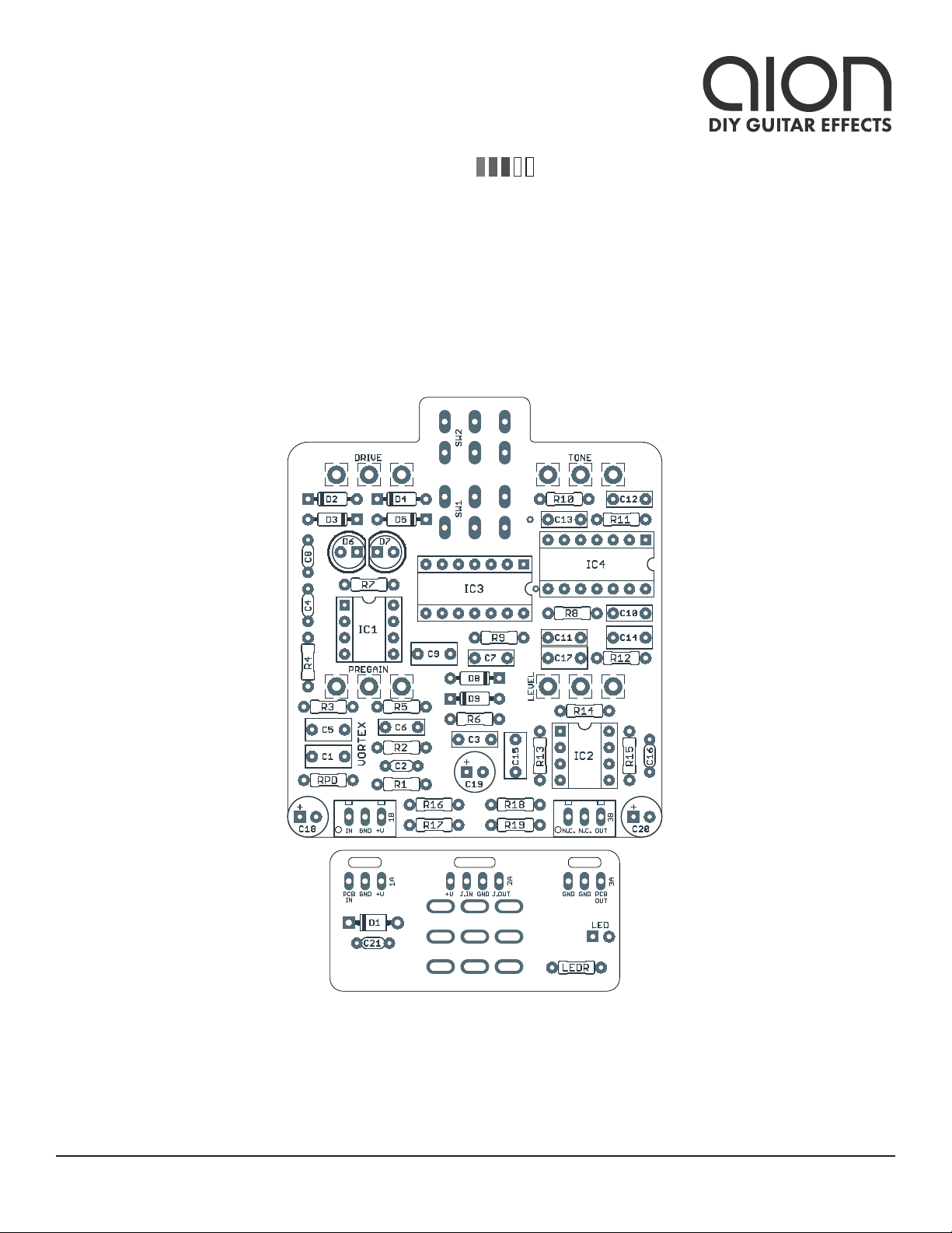
VORTEX AMP DISTORTION 4
PARTS LIST, CONT.
PART VALUE TYPE NOTES
C10 22n Film capacitor, 7.2 x 2.5mm
C11 47n Film capacitor, 7.2 x 2.5mm
C12 2n2 Film capacitor, 7.2 x 2.5mm
C13 22n Film capacitor, 7.2 x 2.5mm
C14 1uF Film capacitor, 7.2 x 3.5mm
C15 1uF Film capacitor, 7.2 x 3.5mm
C16 150pF MLCC capacitor, NP0/C0G
C17 1uF Film capacitor, 7.2 x 3.5mm
C18 100uF Electrolytic capacitor, 6.3mm Power supply filter capacitor.
C19 47uF Electrolytic capacitor, 5mm Reference voltage filter capacitor.
C20 47uF Electrolytic capacitor, 5mm Reference voltage filter capacitor.
C21 100n MLCC capacitor, X7R Power supply filter capacitor.
D1 1N5817 Schottky diode, DO-41
D2 1N914 Fast-switching diode, DO-35
D3 1N914 Fast-switching diode, DO-35
D4 1N914 Fast-switching diode, DO-35
D5 1N914 Fast-switching diode, DO-35
D6 5mm LED LED, 5mm, red diffused Can also use 3mm.
D7 5mm LED LED, 5mm, red diffused Can also use 3mm.
D8 1N914 Fast-switching diode, DO-35
D9 1N914 Fast-switching diode, DO-35
IC1 JRC4558D Operational amplifier, DIP8
IC1-S DIP-8 socket IC socket, DIP-8
IC2 JRC4558D Operational amplifier, DIP8
IC2-S DIP-8 socket IC socket, DIP-8
IC3 CD4066BE CMOS quad analog switch, DIP14
IC3-S DIP-14 socket IC socket, DIP-14
IC4 CD4066BE CMOS quad analog switch, DIP14
IC4-S DIP-14 socket IC socket, DIP-14
PRE 500kB 16mm right-angle PCB mount pot
DRIVE 500kB 16mm right-angle PCB mount pot
TONE 100kB 16mm right-angle PCB mount pot
LEVEL 100kB 16mm right-angle PCB mount pot
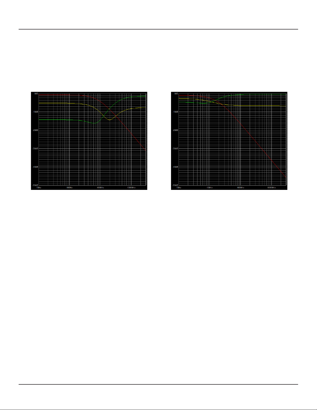
SW1 DPDT on-on Toggle switch, DPDT on-on Selects the clipping diodes for the first two gain stages.
SW2 DPDT on-on Toggle switch, DPDT on-on Selects between two different sets of filters for the tone control.

VORTEX AMP DISTORTION 5
PARTS LIST, CONT.
PART VALUE TYPE NOTES
LED 5mm LED, 5mm, red diffused
IN 1/4" stereo 1/4" phone jack, closed frame Switchcraft 112BX or equivalent.
OUT 1/4" mono 1/4" phone jack, closed frame Switchcraft 111X or equivalent.
DC 2.1mm DC jack, 2.1mm panel mount Mouser 163-4302-E or equivalent.
FSW 3PDT Stomp switch, 3PDT
ENC 125B Enclosure, die-cast aluminum Can also use a Hammond 1590N1.

VORTEX AMP DISTORTION 6
BUILD NOTES
Switches
The original unit has a single toggle switch for either “Rectifier” or “Vintage” mode. Inside, it’s a 4PDT,
with two of the poles controlling the clipping diodes and two of the poles controlling the filters in the
tone section. To provide added flexibility, and also because 4PDT switches are clumsy and somewhat
hard to find, this single switch has been split out into two.
Clipping switch
The clipping switch allows you select between different sets of diodes for the two gain stages. One half
of the switch selects the diodes of the first stage (either two silicon diodes for “Vintage” mode, or no
clipping for “Rectifier” mode) and the other half of the switch selects the diodes of the second stage (two
silicons for “Vintage” or two LEDs for “Rectifier”).
Tone switch
If you look at the schematic, this section looks pretty complex due to the CD4066 switching, but it really
just comes down to each side of the tone control having a different filter value (one resistor and one
capacitor) depending on whether it’s Vintage or Rectifier mode. The DPDT switch becomes eight SPST
switches so that a filter is fully out of the circuit when the other one is engaged.
See next page for more in-depth info on how the tone control behaves and what exactly the toggle
switch does to the sound.

VORTEX AMP DISTORTION 7
BUILD NOTES
Tone control analysis
The tone control is based on the standard Big Muff-style control that fades between a low-pass filter
(bass emphasis, cutting treble) and a high-pass filter (treble emphasis, cutting bass). Here are graphs
showing how the tone control behaves in the different modes.
VINTAGE MODE RECTIFIER MODE
Key:
• Red: 0% rotation (full bass)
• Yellow: 50% rotation (midpoint)
• Green: 100% rotation (full treble)
In Vintage mode, the EQ in the 12:00 position is very similar to a Big Muff with a scooped midrange. In
Rectifier mode, however, it’s largely flat in the middle, with only a slight bass emphasis. The treble side
provides a slight treble increase while the bass side cuts treble significantly. As a result, in Rectifier
mode, the entire character of the control changes, and it becomes basically just a treble control that cuts
to the left.

SCHEMATIC
VORTEX AMP DISTORTION 8
1N5817
100uF
GND
+9V
100n
VA
47uF
47n
47n
22n
22n 2n2
220n
47n
150pF
500pF
500pF
150pF
1M
47k
1k
47k
27k
14k
8k2
27k
47k
100k
100k
220k
100k
100k100k
27k220k
16k
100k
4066N
4066N4066N
4066N
4066N
4066N4066N
4066N
1N914
1N914
1N914
1N914
RED RED
1N914
1N914
GND GND
GNDGND
VB
VB
500kB
500kB
100kB
100kB
VB
VA
GND
VB
GND
GND
VC
VC
GND
VC
GND
VA
GND
GND GND
GND
VA
GND
GND
GND
VB
47uF
GND
2M2
GND
1uF
1uF
1uF
1uF
1uF
1uF
D1
C18
IN
OUT
C21
C19
C11
C7
C10
C13 C12
C6
C3
C2
C4
C8
C16
R1
R3
R4
R5
R7
R6
R8
R9
R12
R18
R13
R15
R14
R16R17
R10R11
R2
R19
IC3A
A
1B2
C
13
IC3B
A
4B3
C
5
IC3C
A8
B
9
C6
IC3D
A11
B
10
C12
IC4A
A
1B2
C
13
IC4B
A
4B3
C
5
IC4C
A8
B
9
C6
IC4D
A11
B
10
C12
IC3P
VDDVSS
7 14
IC1A
2
3
1IC1B
6
5
7
IC2A
2
3
1
IC2B
6
5
7
84
84
D2
D3
D4 D5
D6 D7
SW1A
A2
A3
A1
SW1B
B2
B3
B1
SW2A
A2
A3
A1
SW2B
B2
B3
B1
IC4P
VDDVSS
7 14
D8
D9
DRIVE
1
2
3
PREGAIN
1
2
3
TONE
1
2
3
LEVEL
1
2
3
C20
RPD
C1
C5
C9
C14
C15
C17
GND

VORTEX AMP DISTORTION 9
DRILL TEMPLATE
Cut out this drill template, fold the edges and tape it to the enclosure. Before drilling, it’s recommended
to first use a center punch for each of the holes to help guide the drill bit.
Ensure that this template is printed at 100% or “Actual Size”. You can double-check this by measuring
the scale on the printed page.
Top jack layout assumes the use of closed-frame jacks like the Switchcraft 111X. If you’d rather use
open-frame jacks, please refer to the Open-Frame Jack Drill Template for the top side.
LED hole drill size assumes the use of a 5mm LED bezel, available from several parts suppliers. Adjust
size accordingly if using something different, such as a 3mm bezel, a plastic bezel, or just a plain LED.
0 1 2
CM
0 1
INCH
ø3/8” ø1/2”
0.385”
0.625” 0.625”
x: 0, y: -1.775
ø15/32”
x: -0.775, y: -1.775
ø5/16”
ø3/8”
125B
OUT
TONE
TONE
CLIP
DRIVE
LEVEL PREGAIN
FOOTSWITCHLED
DC IN
x: -0.65, y: +1.71 x: 0.65, y: +1.71
ø9/32” ø9/32”
x: -0.65, y: +0.41
ø9/32”
x: 0.65, y: +0.41
ø9/32”
CENTER (0,0)
x: 0, y: +0.83
ø1/4”
x: 0, y: +1.29
ø1/4”

VORTEX AMP DISTORTION 10
ENCLOSURE LAYOUT
Enclosure is shown without jacks. See next page for jack layout and wiring.
125B

VORTEX AMP DISTORTION 11
WIRING DIAGRAM
125B
IN +VGND NC NC OUT
PCB
IN
GND +V +V JACK GND JACK
OUTIN
GND GND PCB
OUT

VORTEX AMP DISTORTION 12
LICENSE & USAGE
No direct support is offered for these projects beyond the provided documentation. It’s assumed
that you have at least some experience building pedals before starting one of these. Replacements and
refunds cannot be offered unless it can be shown that the circuit or documentation are in error.
All of these circuits have been tested in good faith in their base configurations. However, not all the
modifications or variations have necessarily been tested. These are offered only as suggestions based
on the experience and opinions of others.
Projects may be used for commercial endeavors in any quantity unless specifically noted. No
attribution is necessary, though a link back is always greatly appreciated. The only usage restrictions
are that (1) you cannot resell the PCB as part of a kit without prior arrangement, and (2) you cannot
“goop” the circuit, scratch off the screenprint, or otherwise obfuscate the circuit to disguise its source.
(In other words: you don’t have to go out of your way to advertise the fact that you use these PCBs, but
please don’t go out of your way to hide it. The guitar effects industry needs more transparency, not less!)
DOCUMENT REVISIONS
1.0.1 (2019-08-09)
Corrected drill template. (Tone & Clip were labeled opposite)
1.0.0 (2019-03-03)
Initial release.
Table of contents
Other aion Recording Equipment manuals
Popular Recording Equipment manuals by other brands

Focusrite
Focusrite clarett octopre user guide

iSimple
iSimple PXAUX owner's manual

Technisonic Industries Limited
Technisonic Industries Limited TAC-200A operating instructions

GAI-Tronics
GAI-Tronics 370-901 manual

Behringer
Behringer EUROPOWER PMP500 quick start guide

CTC Parker Automation
CTC Parker Automation PowerStation PA Series user guide