Air 802 AP-G200 User manual

Wireless LAN Device Series
High Power Multi-Mode AP
AP-G200 User Manual
Version. 1.2.2 (24.02.2006)

TABLE OF CONTENTS
PREFACE 1
CH 1.AP-G200 INSTALLATION.........................................................................................................2
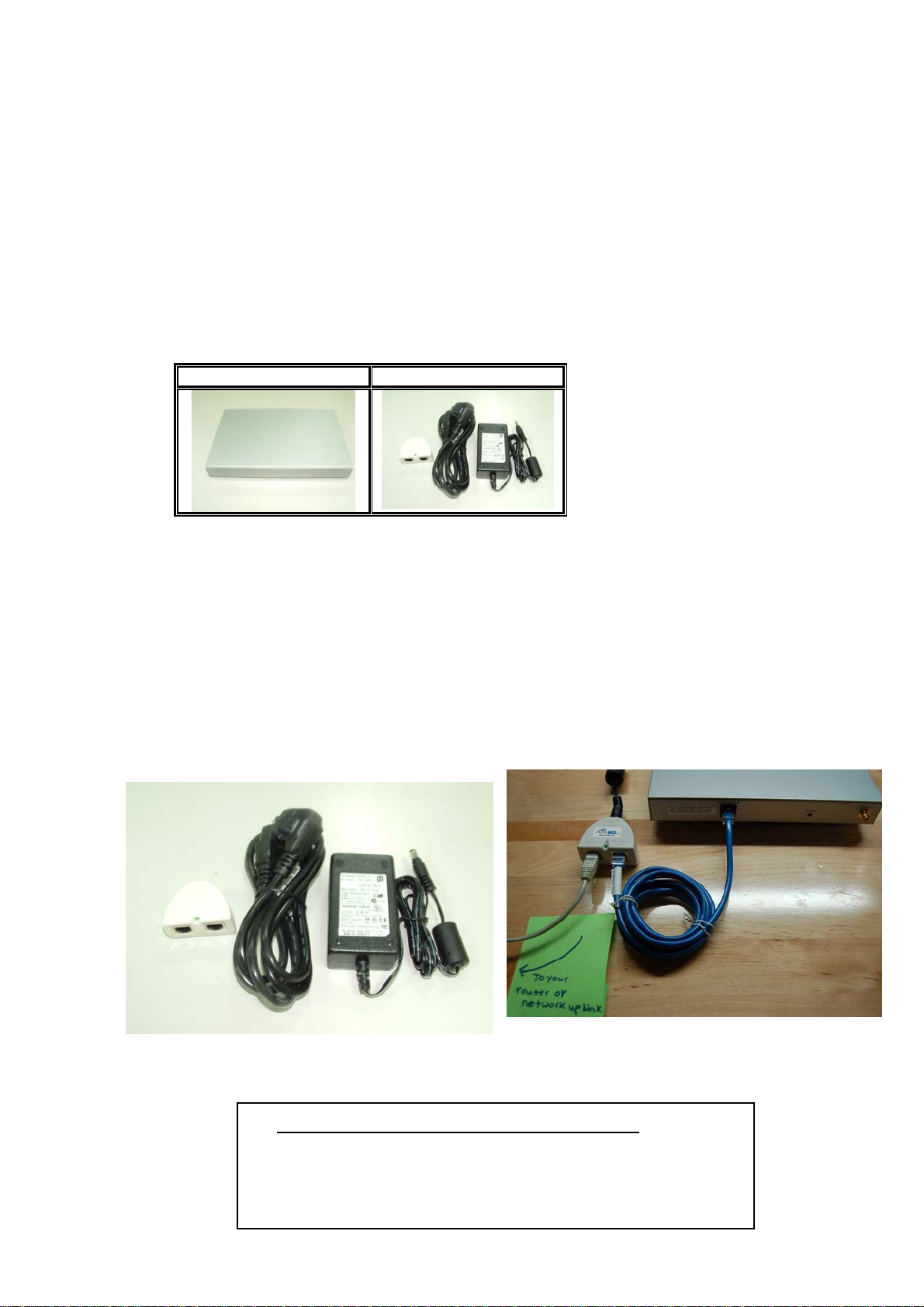
PACKING LIST.......................................................................................................................................2
HARDWARE INSTALLATION...................................................................................................................2
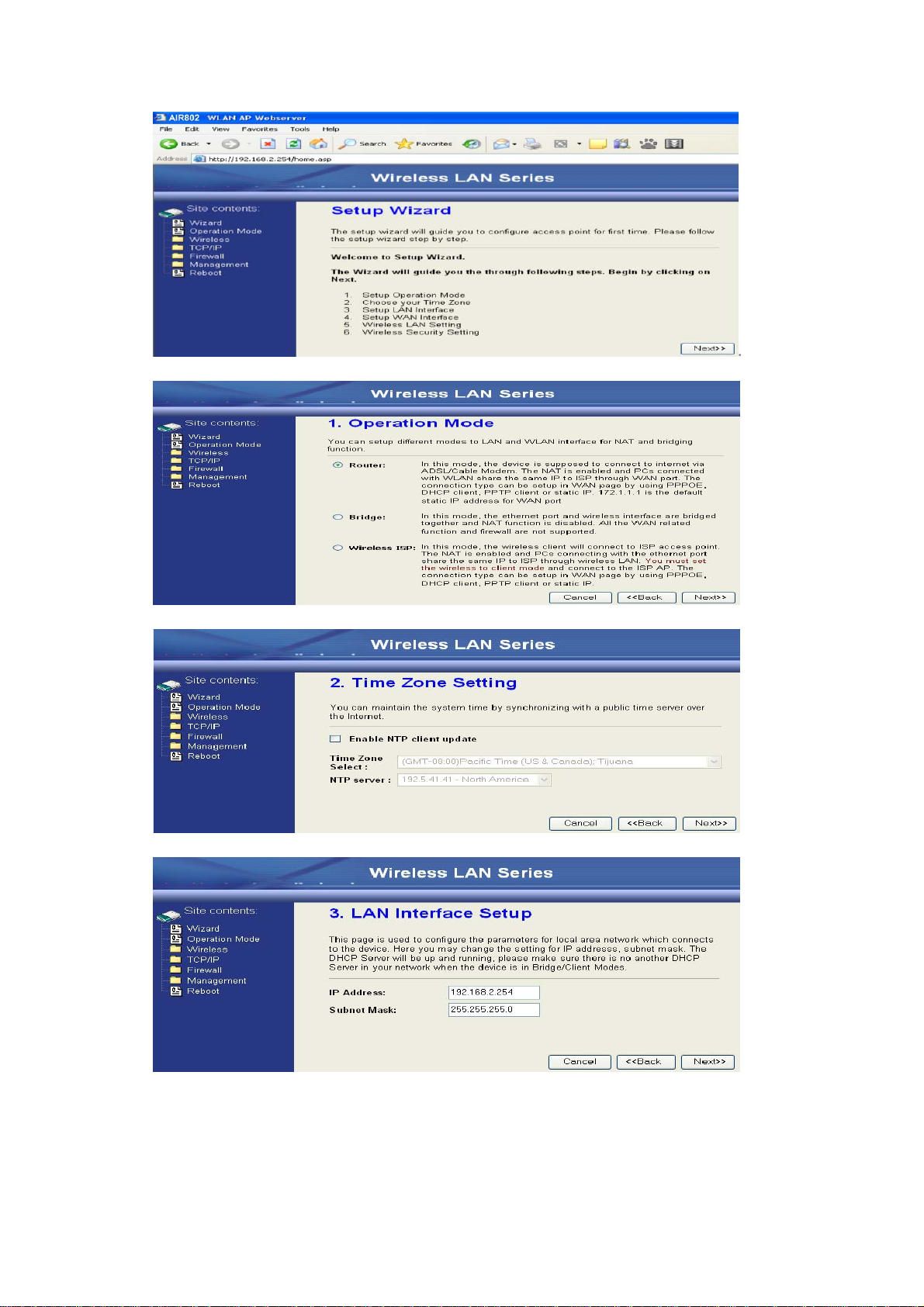
CH 2. FIRST TIME CONFIGURATION ............................................................................................3
BEFORE START TO CONFIGURE .............................................................................................................3
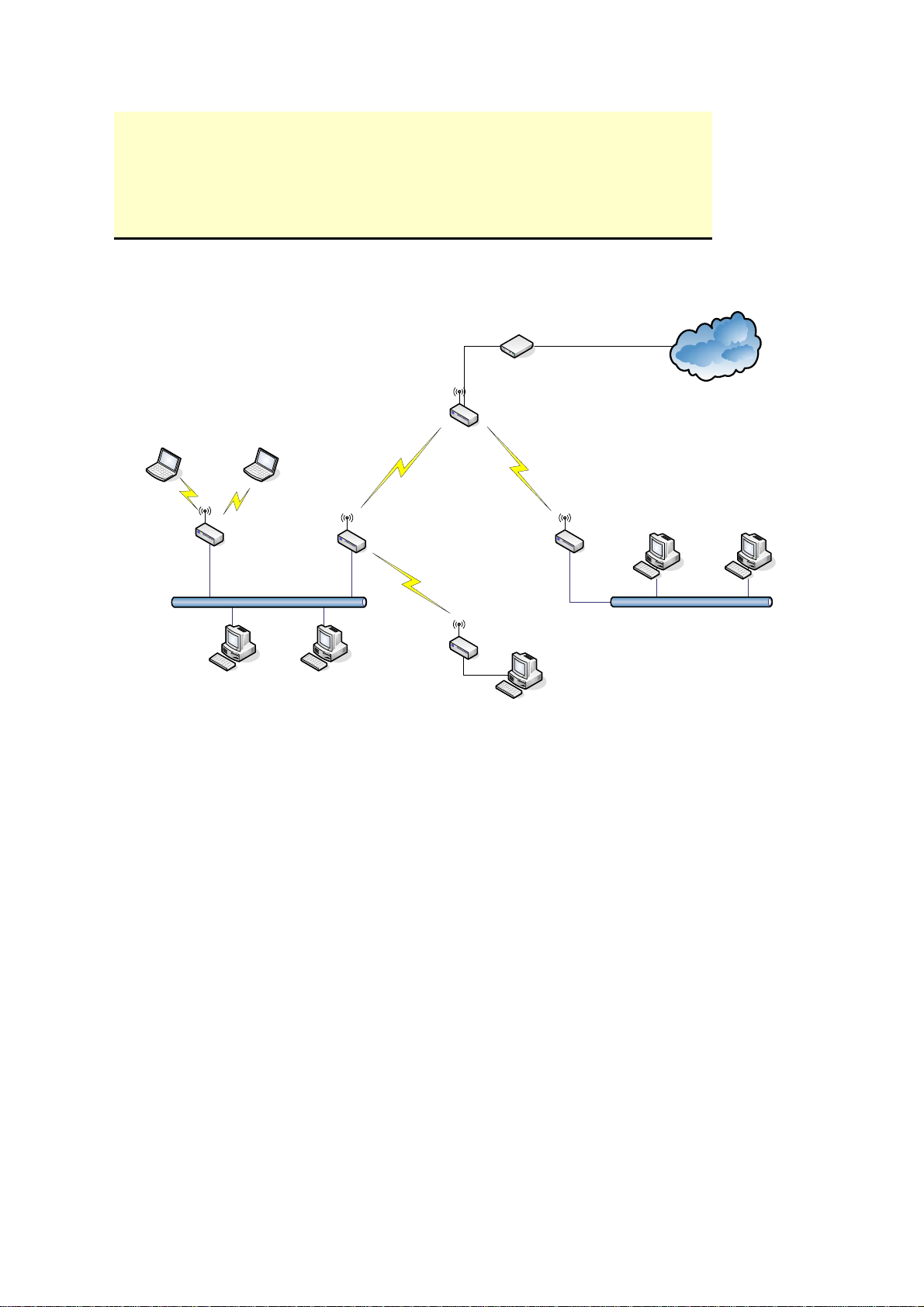
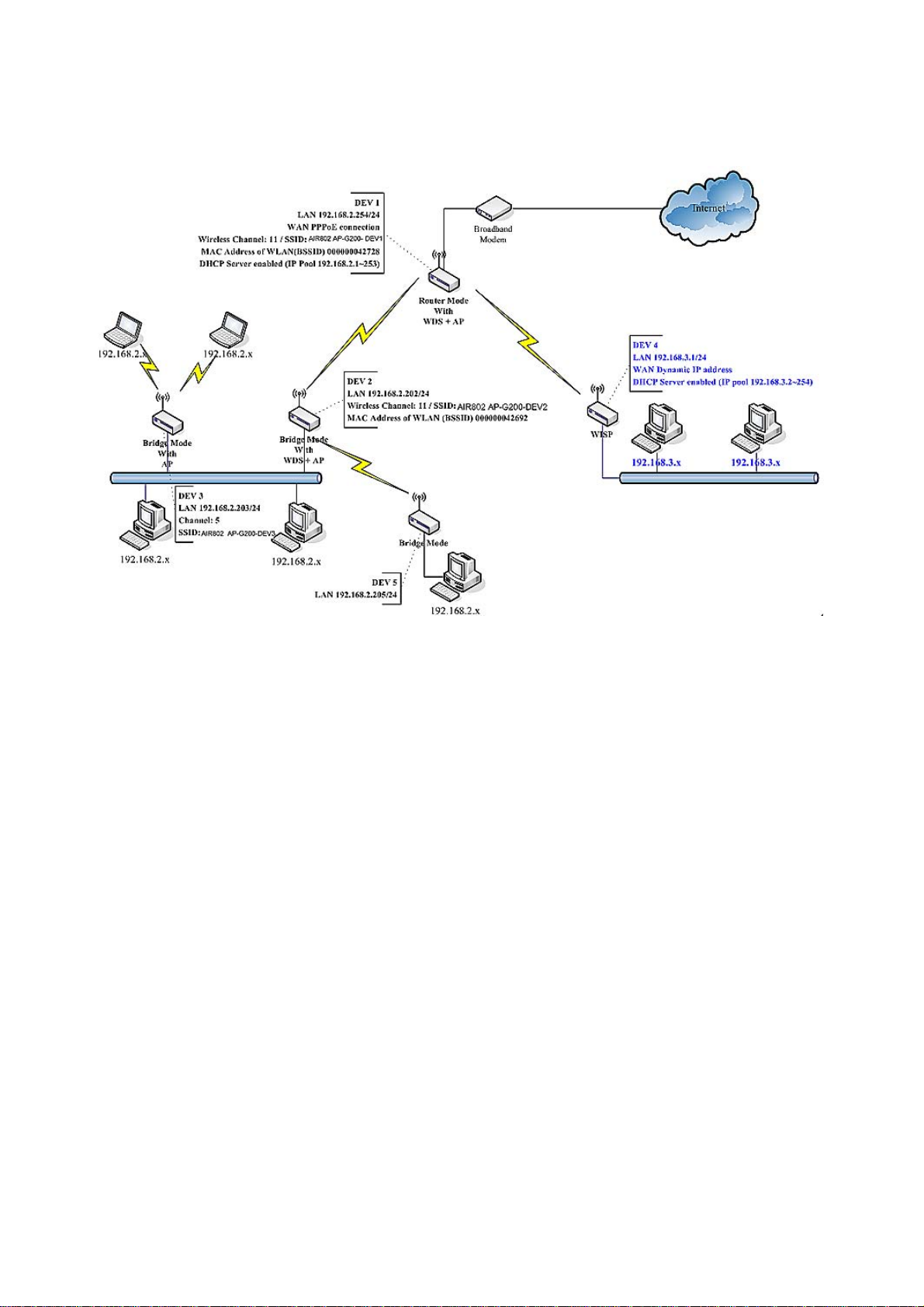
KNOWING THE NETWORK APPLICATION ...............................................................................................3
ADVANCED SETTINGS.........................................................................................................................27
CONFIGURING WIRELESS SECURITY...................................................................................................30
CONFIGURING AS WLAN CLIENTADAPTER.......................................................................................33
QUICK START TO CONFIGURE ..............................................................................................................33
CONFIGURING UNIVERSAL REPEATER ..............................................................................................366
CH 3. CONFIGURINGWDS..............................................................................................................38
WDS NETWORK TOPOLOGY................................................................................................................38
WDSAPPLICATION.............................................................................................................................40
CH 4.ADVANCED CONFIGURATIONS .........................................................................................42
CONFIGURING LAN TO WAN FIREWALL ............................................................................................42
PORT FILTERING .................................................................................................................................42
IPFILTERING ......................................................................................................................................42
MAC FILTERING.................................................................................................................................42
CONFIGURING PORT FORWARDING (VIRTUAL SERVER).......................................................................43
MULTIPLE SERVERS BEHIND NAT EXAMPLE: .....................................................................................44
CONFIGURING DMZ...........................................................................................................................44
CONFIGURING WAN INTERFACE.........................................................................................................45
STATIC IP............................................................................................................................................46
DHCPCLIENT (DYNAMIC IP).............................................................................................................47
PPPOE................................................................................................................................................47
PPTP..................................................................................................................................................48
CONFIGURING CLONE MACADDRESS ...............................................................................................49
CONFIGURING DHCPSERVER ............................................................................................................51
BANDWIDTH CONTROL.......................................................................................................................52
QOS(QUALITY OF SERVICE).............................................................................................................544
STATIC ROUTE SETUP .........................................................................................................................58
DYNAMIC ROUTE SETUP ....................................................................................................................59
VPN PASS-THROUGH..........................................................................................................................60
i

ii
USING CLI MENU...............................................................................................................................60
THE SYSTEM MANAGEMENT ..............................................................................................................63
SNMPAGENT ....................................................................................................................................63
FIRMWARE UPGRADE .........................................................................................................................66
CONFIGURATION DATA BACKUP &RESTORE ......................................................................................67
AUTO DISCOVERY TOOL.....................................................................................................................68
APPENDIXA. BRIDGED NETWORK CONFIGURATION (WITH LINKSYS, ETC.).............42

Preface
This guide is for the networking professional who installs and manages the AIR802 AP-G200
High Power Multi-Mode Indoor AP, hereafter referred to as the “device”. To use this guide, you
should have experience working with the TCP/IP configuration and be familiar with the concepts
and terminology of wireless local area networks.
1

Ch 1. AP-G200 Installation
Packing List
Before you start to install the device, make sure the package contains the following
items:
zAP-G200 High Power Multi-Mode AP
zPoE Power Injector
AP-G200 PoE Power Injector
Hardware Installation
Once you check off everything from the package, you can start to install the device.
You can use the wall mount hole on the bottom of the device to mount the device on
the wall, or just put the device on the desktop. The administrator can refer to the figure
below while constructing your WLAN environment.
Connect Two Ethernet Patch CablesAs Follows:
2
1) Data In: connects to your router or other network uplink
2) P+Data Out: connects to AP-G200 (this provides both
the Ethernet + 48VDC power to the unit)

Ch 2. First Time Configuration
Before Start to Configure
There are two ways to configure the device, one is through web-browser, and the other
is through Secure Shell CLI interface. To access the configuration interfaces, make
sure you are using a computer connected to the same network as the device. The
default IP address of the device is 192.168.2.254, and the subnet-mask is
255.255.255.0.
The device has three operation modes (Router/Bridge/WISP). In bridge mode, also
known as AP Client, you can access the device by both WLAN (Wireless Local Area
Network) and wired LAN. And in router/WISP modes, the device can be accessed by
both WLAN and WAN. The default IP addresses for the device are 192.168.2.254(for
LAN), 172.1.1.1(for WAN), so you need to make sure the IP address of your PC is in
the same subnet as the device, such as 192.168.2.X (for LAN), 172.1.1.X (for WAN).
Please note that the DHCP server inside the device is default to up and running. Do
not have multiple DHCP servers in your network environment, otherwise it will cause
abnormal situation.
We also provide an auto-discovery tool which is for finding out the IP of the device. In
case, you’ve forgot the IP of the device or the IP of the device has been changed, you
can use the tool to find out the IP of the device even your PC is not in the same subnet
as the device is.
Knowing the Network Application
AP-G200 can act as the following roles, and it supports WDS (Wireless Distribution
System) function.
zAccess Point
zWDS (Wireless Repeater)
zBridge/Router
zWISP (See Appendix A for Bridged Wireless Network Configuration)
zAP Client
The device provides 3 different operation modes and the wireless radio of device can act as
AP/Client/WDS. The operation mode is about the communication mechanism between the
wired Ethernet NIC and wireless NIC, the following is the types of operation mode.
Router
3

The wired Ethernet (WAN) port is used to connect with ADSL/Cable modem and the wireless
NIC is used for your private WLAN. The NAT is existed between the 2 NIC and all the
wireless clients share the same public IP address through the WAN port to ISP. The default IP
configuration for WAN port is static IP. You can access the web server of device through the
default WAN IP address 172.1.1.1 and modify the setting base on your ISP requirement.
Bridge
The wired Ethernet and wireless NIC are bridged together. Once the mode is selected, all the
WAN related functions will be disabled.
WISP (Wireless ISP)
This mode can let you access the AP of your wireless ISP and share the same public IP address
form your ISP to the PCs connecting with the wired Ethernet port of the device. To use this
mode, first you must set the wireless radio to be client mode and connect to the AP of your ISP
then you can configure the WAN IP configuration to meet your ISP requirement.
The wireless radio of the device acts as the following roles.
AP (Access Point)
The wireless radio of device serves as communications “hub” for wireless clients and provides
a connection to a wired LAN.
AP Client
This mode provides the capability to connect with the other AP using infrastructure/Ad-hoc
networking types. With bridge operation mode, you can directly connect the wired Ethernet
port to your PC and the device becomes a wireless adapter. And with WISP operation mode,
you can connect the wired Ethernet port to a hub/switch and all the PCs connecting with
hub/switch can share the same public IP address from your ISP.
WDS (Wireless Distribution System)
This mode serves as a wireless repeater; the device forwards the packets to anotherAP with
WDS function. When this mode is selected, all the wireless clients can’t survey and connect to
the device. The device only allows the WDS connection.
WDS+AP
This mode combines WDS plusAP modes, it not only allows WDS connections but also the
wireless clients can survey and connect to the device.
The following table shows the supporting combination of operation and wireless radio modes.
Bridge Router WISP
AP V V X
4

WDS V V X
Client V X V
AP+WDS V V X
Hereafter are some topologies of network application for your reference.
Bridge Mode
With
AP
Bridge Mode
With
WDS + AP
Bridge Mode
Router Mode
With
WDS + AP
WISP Mode
Internet
Broadband
Modem
5

Examples of Configuration
This example demonstrates how to set up a network with different device configurations.
There are 2 DHCP servers (DEV1/DEV4) in the network to control the IP configuration of 2
domains (192.168.2.x/192.168.3.x). Once the setting is done, all the PCs can visit Internet
through DEV1.
We assume all the devices keep the factory default setting. To make sure that user can
continuing press the rest button for more than 5 seconds to restore the factory default setting.
The following descriptions show the steps to configure DEV1 to DEV5.
Configure DEV1:
1. Connect the ADSL modem to Ethernet port of device using Ethernet cable.
2. Access the web server (http://192.168.2.254) of device from the wireless station.
3. Use Wizard page to setup device.
6

4. Press “Next>>” button then set the “Operation Mode” to “Router” mode.
5. Press “Next>>” button then disable “Time Zone” function.
6. Press “Next>>” button then set the IP address of LAN interface.
7. Press “Next>>” button then select the “PPPoE” for “WAN Access Type” and fill in the
“User Name” and “Password” fields.
7

8. Press “Next>>” button then select the “AP+WDS” for “mode” and change the SSID to
“DEV1”.
9. Press “Next>>” button then select “None” for “Encryption” then press “Finished” button.
10. Wait for refreshing web page.
11. Use “WDS Settings” page to configure WDS.
8

12. Enable WDS function and add the BSSID of DEV2 to “Current WDS AP List”.
13. Since we access the device by wireless connection, it may temporarily disconnect when
applying the WDS setting.After re-connecting to the device, use the “Status” page to
check the settings.
9

10

Configure DEV2:
1. Access the web server (http://192.168.2.254) of device from the Ethernet port.
Caution
If you configure multiple devices in the same PC, since the devices
have the same default IP address but different MAC addresses, it may
cause you not able to access the web server of device. If the situation
happens, please try to clean the ARP table of your PC by DOS
command “arp –d” then you can access the web server of device
using the default IP address.
2. Use Wizard page to setup device.
3. Press “Next>>” button then set the “Operation Mode” to “Bridge” mode.
4. Press “Next>>” button then disable “Time Zone” function.
5. Press “Next>>” button then set the IP address of LAN interface.
11

6. Press “Next>>” button then select the “AP+WDS” for “mode” and change the SSID to
“DEV2”.
7. Press “Next>>” button then select “None” for “Encryption” then press “Finished” button.
8. Wait for refreshing web page.
12

9. Access the web server by new IP address “192.168.2.202” then use “LAN Interface”
page to disable DHCP Server.
10. Wait for refreshing web page.
11. Use “WDS Settings” page to configure WDS.
13

12. Enable WDS function and add the BSSID of DEV1 to “Current WDS AP List”.
13. Use the “Status” page to check the settings.
14

Configure DEV3:
1. Access the web server (http://192.168.2.254) of device from the Ethernet port.
Caution
If you configure multiple devices in the same PC, since the devices have the
same default IP address but different MAC addresses, it may cause you not
able to access the web server of device. If the situation happens, please try
to clean the ARP table of your PC by DOS command “arp –d” then you can
access the web server of device using the default IP address.
2. Use “LAN Interface” page to set the IP address of LAN interface and disable DHCP
server.
3. Wait for refreshing web page.
15

4. Access the web server by new IP address “192.168.2.203” then use “Basic Settings” page
to change SSID and CHANNEL.
5. Use the “Status” page to check the settings.
16

Configure DEV4:
1. Access the web server (http://192.168.2.254) of device from the Ethernet port.
Caution
If you configure multiple devices in the same PC, since the devices have the
same default IP address but different MAC addresses, it may cause you
unable to access the web server of device. If the situation happens, please
try to clean the ARP table of your PC by DOS command “arp –d” then you
can access the web server of device using the default IP address.
2. Use Wizard page to setup device.
3. Press “Next>>” button then set the “Operation Mode” to “Wireless ISP” mode.
4. Press “Next>>” button then disable “Time Zone” function.
5. Press “Next>>” button then set the IP address of LAN interface.
17
Table of contents
Other Air 802 Wireless Router manuals
Popular Wireless Router manuals by other brands

ARCHITECTURE TECHNOLOGY CORPORATION
ARCHITECTURE TECHNOLOGY CORPORATION CRR-1000 quick start guide

SMC Networks
SMC Networks SMCBR14 WIRED BARRICADE user guide

D-Link
D-Link DVA-2800 quick start guide

Belkin
Belkin F5D7230-4 user manual

Aztech
Aztech HW550-3G user manual

ZyXEL Communications
ZyXEL Communications ZyAir G-2000 PlusV2 user guide