Customer : CSN
Type : A318/A319/A320/A321
Rev. Date : May 01, 2018
Manual : AMM
Selected applicability : 0054-0054
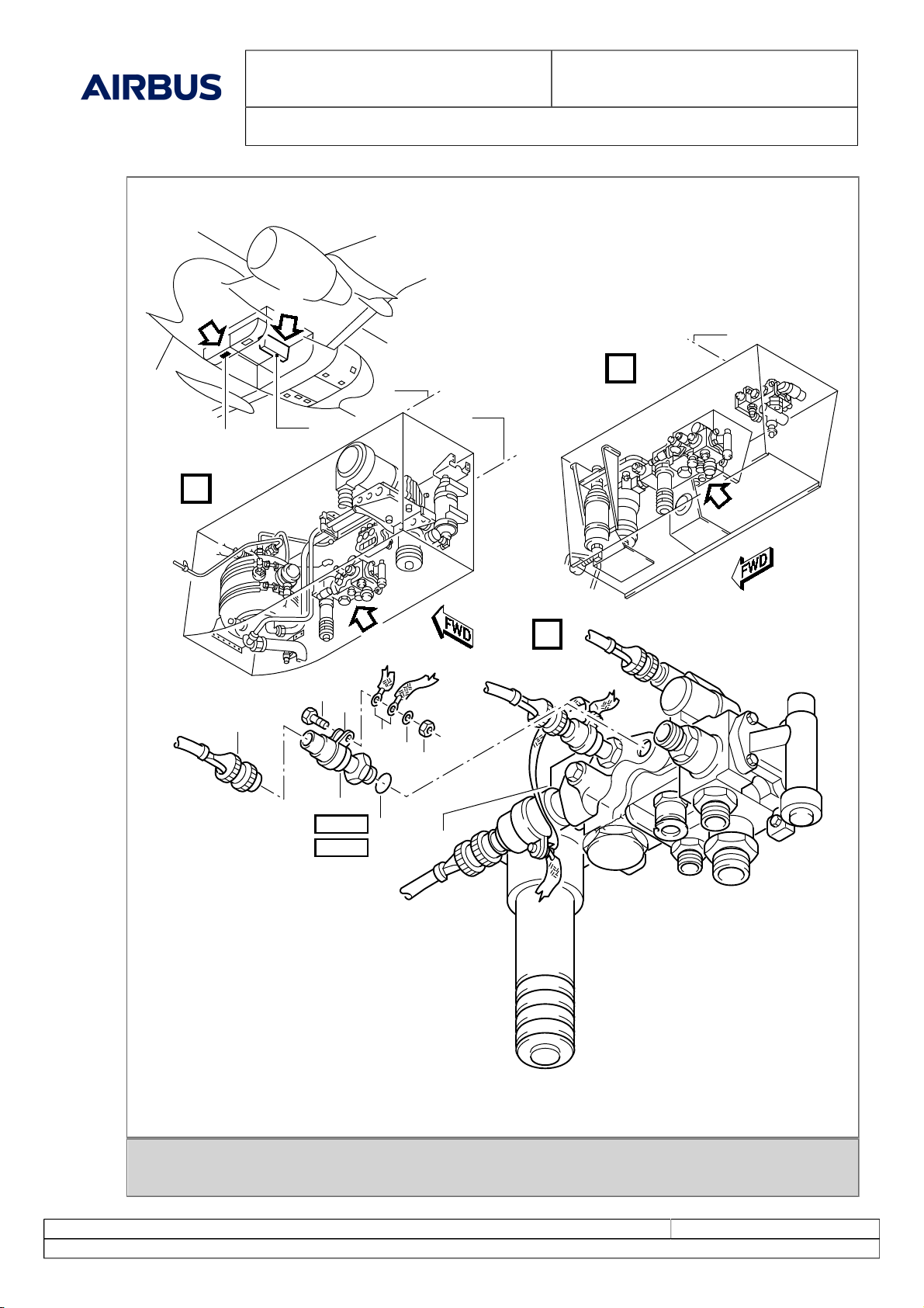
29-32-12 PB 401 CONF 00 - PRESSURE
SWITCH - SYSTEM - REMOVAL/INSTALLATION
Print Date: July 05, 2018 Page 6 of 19
© AIRBUS S.A.S. ALL RIGHTS RESERVED. CONFIDENTIAL AND PROPRIETARY DOCUMENT.
PANEL DESIGNATION FIN LOCATION
49VU FLIGHT CONTROLS/ELAC1/NORM/
SPLY 15CE1 B11
105VU FLIGHT CONTROLS/ELAC2/STBY SPLY 16CE2 A02
105VU FLT CTL/ELAC1/STBY SPLY 16CE1 A01
121VU FLIGHT CONTROLS/SEC3/SPLY 21CE3 Q19
121VU FLIGHT CONTROLS/SEC2/SPLY 21CE2 Q18
121VU FLIGHT CONTROLS/ELAC2/NORM/
SPLY 15CE2 R20
4. Procedure
(Ref. Fig. System Pressure Switch of the Green and Yellow Hydraulic Systems SHEET 1)
Subtask 29-32-12-420-050-A
A. Installation of the System Pressure Switch
(1) Clean the component interfaces and the adjacent area.
(2) Do an inspection of the component interfaces and the adjacent area.
(3) Lubricate the new IPC -CSN (29-32-03-01-070) O-ring (3) or IPC -CSN (29-32-83-01-090) O-ring (3)
with Phosphate Ester Hydraulic Fluid-General Power - - (Material No. 02ABA1).
(4) Remove the blanking plugs from the ports of the manifold.
(5) Put the new O-ring (3) in position on the system pressure switch (2).
(6) Install the system pressure switch (2) in the manifold (4).
(7) TORQUE the system pressure switch (2) to between 3.20 and 3.45 m.daN (23.60 and 25.44 lbf.ft).
(8) Safety the system pressure switch (2) with lockwire, corrosion-resistant steel 0.8 mm (0.032 in.)
(9) Install the clamp (9), the bonding jumper (7), the screw (8), the washer (6) and the nut (5) at the
system pressure switch (2) (Ref. AMM TASK 20-28-00-912-004) .
(10) Remove the blanking cap from the electrical connector.
(11) Make sure that all the electrical connections are clean and in the correct condition.
(12) Connect the electrical connector (1) to the system pressure switch (2).
Subtask 29-32-12-865-053-A
B. Remove the safety clip(s) and the tag(s) and close this(these) circuit breaker(s):
PANEL DESIGNATION FIN LOCATION
49VU FLIGHT CONTROLS/ELAC1/NORM/
SPLY 15CE1 B11
105VU FLIGHT CONTROLS/ELAC2/STBY SPLY 16CE2 A02
105VU FLT CTL/ELAC1/STBY SPLY 16CE1 A01
121VU FLIGHT CONTROLS/SEC3/SPLY 21CE3 Q19
121VU FLIGHT CONTROLS/SEC2/SPLY 21CE2 Q18
121VU FLIGHT CONTROLS/ELAC2/NORM/
SPLY 15CE2 R20
Subtask 29-32-12-790-050-A
C. Leak Test of the Hydraulic Connections
(1) Pressurize the reservoir of the Green hydraulic system (Ref. AMM TASK 29-14-00-614-002) .