Air Comm Systems ACS 296 User manual

Receive Audio Indicator Panel
Installation Manual
Revision 1.7
ACS 296
Air Comm Systems, Inc
37610 Sky Canyon Dr. Hangar 51
Murrieta, CA 92563
Ph: 951-677-0101 ~ Fx: 951-677-0701
[email protected] ~ www.AirCommSystems.com
VHF1
VHF2
VHF3
FM1
FM2
FM3

Air Comm Systems, Inc. Page 2
nInstallation
General Operating Specifications Page 3
Physical Dimensions Page 4
Page 5
n
Interface Schematic
Instructions for Continued Airworthiness
Page 6
nWarranty Information
Air Comm Systems Warranty Page 7
ACS 296 Installation Manual
Table of Contents

Air Comm Systems, Inc. Page 3
nOperating Specifications
ACS 296 Installation Manual
General Operating Specifications
Audio Input: Up to 6 audios
Duty Cycle: Continuous
Power Requirements: 28V DC +/- 10%
Maximum Operating Altitiude: 22,000 ft.
Operating Temperature Range: -40 C to +85 C (operating), -65 C to +125 C (storage)
Current Drain: 100mA minimum; 750 mA maximum
nUnit Description
The ACS 296 Receive Audio Indicator Panel is a compact, Dzus mounted unit that provides a
visual status of which receive audios are active in the aircraft audio system. The ACS 296 is
designed to be interfaced with a Single or Dual Channel Audio Mixer Panel and installed in close
proximity to that panel for easy reference by the user.
nMethod of Operation
The ACS 296 senses the incoming receive audios and displays the active status on the the front
panel. The active status is indicated by a glowing green LED. The intensity of the indicator is
controlled by a photo sensor located on the front of the ACS 296; as the ambient light conditions
change in the cockpit or cabin, so will the LED intensity.
The threshold is factory set with 2.0 MW audio on each audio input line one thru six. The threshold
pots on the left side of the panel can be set for each audio input to make the light come on.
nPhysical Specifications
Weight: .75 lb. (0.38 kg)
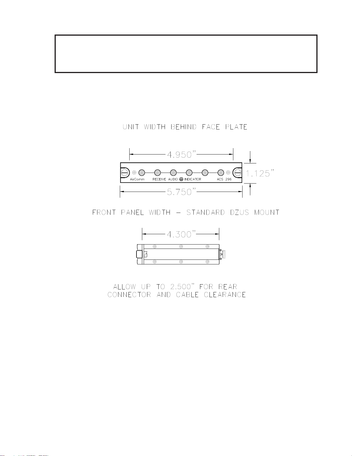
Size:
Illumination: Edge lit front panel per MIL-P-7738E,type 5. Capable of connection to
dimmer bus for adjustment. RX Status indicators are 5.0V Green
LED’s. NVG can be included upon request.
Mounting: Standard Dzus rail mount, two (2) fasteners
Controls: None
5.75 in. (14.61 cm) W
1.125 in. ( 2.86 cm) H
4.30 in. (10.92 cm) D

Air Comm Systems, Inc. Page 4
The ACS 296 is designed to be Dzus mounted in close proximity to the Audio Mixer Panel it will interface
with. The unit should be installed in the aircraft using the Installation kit that was included. The above
outline drawing of the unit with dimensions will facilitate the installation.
The Installation Kit consists of the following:
One (1) 9 pin AMP D-Subminiature mating connector (female) complete with crimp pins, hood, and
slidelock.
The connector pin configuration of the ACS 296 rear connector and the recommended wire size for the
aircraft cable harness is shown on the following page.
nPhysical Dimension Outline
ACS 296 Installation Manual
Physical Dimensions
VHF1
VHF2
VHF3
FM1
FM2
FM3

Air Comm Systems, Inc. Page 5
The ACS 296 wiring harness should be constructed of Tefzel aircraft wire (M22759/34 grade). Power and
ground wires should be 22 AWG. Shielded wires should be used where noted. Adequate protection
against wear and chafing should be taken by using a braided cable sleeving or jacket. Before
completing installation, verify that all cable connector pins are seated properly and that the connector is
securely mounted to the unit mating connector.
Pre-fabricated cable harnesses are available from Air Comm to expedite installation - consult our
sales department for details.
nConnector Schematic
ACS 296 Installation Manual
Interface Schematic

Air Comm Systems, Inc. Page 6
Instruction for continued airworthiness forReceive Audio Indicator Panel Model ACS-296.
GENERAL DESCRIPTION:
The ACS 296 Receive Audio Indicator Panel is a compact, Dzus mounted unit that provides
a visual status of which receive audios are active in the aircraft audio system. The ACS 296
is designed to be interfaced with a Single or Dual Channel Audio Mixer Panel and installed in
close proximity to that panel for easy reference by the user.
PURPOSE:
To provide instructions for the maintenance and inspection of the Air Comm Systems, Inc.
Model ACS-296 Receive Audio Indocator Panel.
This Manual provides instructions supplementing the aircraft maintenance manual.
These instructions only supersede the aircraft manual in the indicated areas.
OPERATIONAL CHECK:
The Receive Audio Indicator Panel should be checked prior to first flight each day per
current operations manual.
MAINTENANCE:
Check security and condition of Dzus mounted panel(s), check associated wiring hareness
at periodic inspections such as annual/100 hour IAW FAR43 Appendix D(i).
On Condition.
Send Receive Audio Indicator Panels to qualified repair facility for any repairs. Contact Air Comm
Systems, Inc. Phone 951-677-0101 or FAX 951-677-0701 for nearest factory authorized
repair facility.
ACS 296 Installation Manual
Airworthiness Insrtuctions

Air Comm Systems, Inc. Page
7
ACS 296 Installation Manual
Warranty Information
n
Warranty Information
Air Comm Systems, Inc. warrants each new product to be free from defective material and
workmanship and agrees to remedy any defect or to furnish a new part in exchange for any
defective unit provided an examination discloses such defect occurred under normal use and service,
and provided the defective unit is delivered to us, with transportation charges prepaid, within 1 year
from the date of acceptance of equipment by the owner. Each unit required and claimed defective must
be returned to:
This warranty does not extend to any products which have been subjected to misuse, neglect, accident,
or in violation of instructions furnished, nor does it extend to units which have been repaired or altered
outside of our factory except where such repairs are specifically authorized in writing by us.
This warranty is in lieu of all other warranties expressed or implied, and no representative or
person is authorized to assume for us any other liability in connection with the sale of our products.
Air Comm Systems, Inc.
37610 Sky Canyon Dr. Hangar 51
Murrieta, CA 92563
Ph: 951-677-0101
Fx: 951-677-0701
Table of contents
Popular Measuring Instrument manuals by other brands

Endress+Hauser
Endress+Hauser Flowfit CYA27 operating instructions

Anritsu
Anritsu MP1632C Operation manual

Sper scientific
Sper scientific 800058 manual

LaserLine
LaserLine SuperCross-Laser 2P operating instructions

ALGE-Timing
ALGE-Timing Windspeed WS2 manual

ADA INSTRUMENTS
ADA INSTRUMENTS ZHT 125 Electronic operating manual