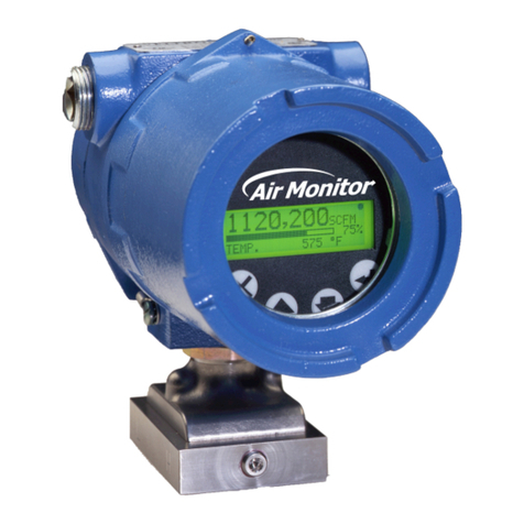
Air Monitor VELTRON DPT 2500-plus User manual

Installation, Operation,
and Maintenance Manual
VELTRON DPT 2500-plus
Microprocessor Based Ultra-Low Range
Pressure & Flow "Smart" Transmitter
Version 1.0X
Installation, Operation & Maintenance
Air Monitor Corporation provides complete
technical support between the hours of
7 a.m. and 5 p.m. PST, M-F
Contact our Service Department
Toll Free: 1-800-AIRFLOW
or fax us at 1-707-526-2825
Air Monitor Corporation
116-047-20.PMD (5/5/11)
VELTRON DPT 2500-plus - IO&M Manual


VELTRON DPT 2500-plus
Air Monitor Corporation
116-047-20.PMD (5/5/11)
VELTRON DPT 2500-plus - IO&M Manual
TABLE OF CONTENTS
TABLE OF CONTENTS
INSTRUMENT WARRANTY .................................................................................................................... i
SECTION 1 – GENERAL INFORMATION
1.1 DESCRIPTION ............................................................................................................................... 1
1.2 THEORY OF OPERATION ............................................................................................................. 1
SECTION 2 – PERFORMANCE SPECIFICATIONS
2.1 TRANSMITTER .............................................................................................................................. 2
2.2 INDICATION ................................................................................................................................... 2
2.3 OUTPUTS ...................................................................................................................................... 2
2.4 POWER .......................................................................................................................................... 2
SECTION 3 – FEATURES
3.1 USER SETUP MENU ..................................................................................................................... 3
3.2 TRANSMITTER HOLD ................................................................................................................... 3
3.3 AUTOMATIC ZEROING ................................................................................................................. 3
3.4 DATA DISPLAY ............................................................................................................................... 3
3.5 HIGH TURNDOWN RATIO OPERATION ....................................................................................... 3
3.6 ENCLOSURE ................................................................................................................................. 3
3.7 MULTIPLE OPERATING POWER SELECTIONS .......................................................................... 3
SECTION 4 – INSTALLATION
4.1 RECEIVING AND INSPECTION .....................................................................................................4
4.2 LOCATION ..................................................................................................................................... 4
4.3 MOUNTING .................................................................................................................................... 5
4.4 PROCESS CONNECTIONS ........................................................................................................... 6
4.5 POWER/SIGNAL CONNECTIONS ................................................................................................ 7
4.6 OUTPUT SELECTION ................................................................................................................... 7
4.7 DISPLAY CONTRAST ADJUSTMENT ........................................................................................... 7
SECTION 5 – OPERATION
5.1 INTRODUCTION ............................................................................................................................ 8
5.2 START-UP ...................................................................................................................................... 8
5.3 NORMAL OPERATION .................................................................................................................. 9
5.4 CONFIGURATION .......................................................................................................................... 9
5.5 PUSHBUTTON DEFINITION ........................................................................................................10
5.6 CONFIGURATION PROGRAMMING ...................................................................................... 11-12
5.7 TRANSMITTER SCALING & CONFIGURATION .................................................................... 13-17
5.8 LOW PASS FILTER ...................................................................................................................... 18
5.9 AUTO-zero CONFIGURATION ..................................................................................................... 19
5.10 TRANSDUCER SPAN SELECTION ............................................................................................. 20
5.11 TRANSMITTER INPUT CALIBRATION ........................................................................................ 21
5.12 TRANSMITTER OUTPUT CALIBRATION .................................................................................... 21

TABLE OF CONTENTS
SECTION 6 – CALIBRATION
6.1 REQUIRED EQUIPMENT ............................................................................................................ 22
6.2 PREPARATION ............................................................................................................................ 22
6.3 TRANSMITTER INPUT CALIBRATION ................................................................................... 23-25
6.4 TRANSMITTER OUTPUT CALIBRATION ............................................................................... 26-27
SECTION 7 – MAINTENANCE ............................................................................................................. 28
SECTION 8 – TROUBLESHOOTING ................................................................................................... 29
SECTION 9 – PARTS LIST ................................................................................................................... 30
SECTION 10 – CUSTOMER SERVICE................................................................................................. 31
TABLE OF CONTENTS
VELTRON DPT 2500-plus
Air Monitor Corporation
116-047-20.PMD (5/5/11)
VELTRON DPT 2500-plus - IO&M Manual

VELTRON DPT 2500-plus
Air Monitor Corporation
116-047-20.PMD (5/5/11)
VELTRON DPT 2500-plus - IO&M Manual
i
INSTRUMENT WARRANTY
NOTICE OF PROPRIETARY RIGHTS
This document contains confidential technical data, including
trade secrets and propriet ary information which are the sole
property of Air Monitor Corporation. The use of said data is
solely limited to use as specified herein. Any other use is strictly
prohibited without the prior written consent of Air Monitor
Corporation.
INSTRUMENT WARRANTY
Air Monitor Corporation (hereinafter referred to as “Seller”)
warrants that at the time of shipment, products sold
pursuant to this contract will be free from defects in
materials and workmanship, and will conform to the
specifications furnished or approved in writing by Seller.
No warranty is given that delivered products will conform
to catalog sheets, data sheets, and the like, which are
subject to change without notice.
Seller will repair or replace, at its option, any products
listed under this warranty which is returned freight prepaid
to Seller within the earlier of three (3) years after start-up
or thirty-nine (39) months after shipment that, upon test
and examination, proves defective within the terms of
this warranty. The warranty period for any item repaired
or replaced shall be for the time remaining on the warranty
period of the original components. Purchaser shall notify
Seller in writing of such defect within sixty (60) days of
discovery of the defect.
This warranty does not extend to any product sold by
Seller which has been the subject of misuse, neglect,
accident, damage or malfunction caused by
interconnection with equipment manufactured by others,
improper installation or storage, or used in violation of
instructions furnished by Seller, nor does it extend to any
product which has been repaired or altered by persons
not expressly approved by Seller. Nor does Seller warrant
equipment against normal deterioration due to
environment; nor items such as lamps, glass, and similar
items subject to wear or burnout through usage.
Adjustments for items or equipment not manufactured
by Seller shall be made to the extent of any warranty of
the manufacturer or supplier thereof.
Seller shall not be liable for any special or consequential
damages or for loss of damage, directly or indirectly
arising from the use of the products. Seller's warranty
shall be limited to replacement of defective equipment
and shall not include field removal and installation
expenses.
The warranty set forth above is in lieu of all other
warranties either express or implied and constitutes the
full extent of Air Monitor Corporation's liability to the
customer, or any other party for breach of warranty.
THERE ARE NO EXPRESS WARRANTIES EXCEPT AS
SET FORTH HEREIN AND THERE ARE NO IMPLIED
WARRANTIES OF MERCHANTABILITY OF FITNESS
FOR ANY PARTICULAR PURPOSE, WHICH ARE
PARTICULARLY DISCLAIMED.

VELTRON DPT 2500-plus
Air Monitor Corporation
116-047-20.PMD (5/5/11)
VELTRON DPT 2500-plus - IO&M Manual
1
SECTION 1 – GENERAL INFORMATION
1 – GENERAL INFORMATION
1.1 – DESCRIPTION
The VELTRON DPT 2500-plus is an ultra-low differential pressure "smart" transmitter designed to convert the low
magnitude pressure signals generated by airflow stations and probes, or static pressure sensors into an output signal
(4-20mA, 0-5VDC or 0-10VDC) linear to pressure or flow.
Each VELTRON DPT 2500- plus is equipped with numerous standard features: A multi-line LCD used during
configuration/calibration and for display of process; AUTO-zero for elimination of transmitter zero error; user selectable
primary signal noise filter, input power isolation; capability of 10:1 flow or 100:1 pressure turndown; and an optional
NEMA 12 enclosure (NEMA 1 is standard).
1.2 – THEORY OF OPERATION
High and low pressure signals generated by airflow stations and probes, or static pressure sensors act upon opposite
sides of a flexible diaphragm within the transducer. The differential between the two pressure signals displaces the
diaphragm; the magnitude of the displacement being measured creates an electrical DC output from the transducer.
After undergoing A/D conversion, the resulting digit al signal representing differential pressure or velocity pressure
can be "manipulated" within the microprocessor: square rooted for velocity or flow application; scaled for unit s of
measure and area for process output; and scaled for local data display. The built-in microprocessor runs the program
that provides the following basic functions: Timing, logic, and mathematical operations, analog input signal multiplexing,
analog input/output calibration, automatic zeroing valve operation, User Setup menu system, and display (LCD)
indication.

VELTRON DPT 2500-plus
Air Monitor Corporation
116-047-20.PMD (5/5/11)
VELTRON DPT 2500-plus - IO&M Manual
2
SECTION 2 – PERFORMANCE SPECIFICATIONS
2 – PERFORMANCE SPECIFICATIONS
2.1 – TRANSMITTER
Accuracy. 0.25% of Natural Span, including hysteresis,
deadband, non-linearity, and non-repeatability.
Type. Differential pressure, flow, and mass flow.
Ranges.Natural Spans Bi-Polar Natural Spans
0 to 25.00 IN w.c.
0 to 10.00 IN w.c. –10.00 to 10.00 IN w.c.
0 to 5.00 IN w.c. – 5.00 to 5.00 IN w.c.
0 to 2.00 IN w.c. – 2.00 to 2.00 IN w.c.
0 to 1.00 IN w.c. – 1.00 to 3.00 IN w.c.
0 to 0.50 IN w.c. – 0.50 to 0.50 IN w.c.
0 to 0.25 IN w.c. – 0.25 to 0.25 IN w.c.
0 to 0.10 IN w.c. – 0.10 to 0.10 IN w.c.
0 to 0.05 IN w.c. – 0.05 to 0.05 IN w.c.
Span Rangeability. The calibrated span can be down
ranged to 40% of the Natural Span.
Stability. ±0.5% of Natural Span for six months.
Temperature Effect.
Zero. None; corrected by AUTO-zero.
Span. 0.015% of Natural Span/ºF.
Mounting Position Effect. None; corrected through
transmitter automatic zeroing.
Span and Zero Adjustment. Digital, via internally
located pushbuttons.
Low Pass Filtration. Response time to reach 98% of
a step change is adjustable from 0.5 to 256.0
seconds.
Overpressure and Static Pressure Limit. 25 psig.
Automatic Zeroing.
Accuracy. Within 0.1% of calibrated span.
Frequency. Every 1 to 24 hours on 1 hour intervals.
Temperature Limits. –20 to 180ºF Storage; +40 to
140ºF Operating.
Humidity Limits. 0-95% RH, non-condensing.
2.2 – INDICATION
Display. A backlit, graphical LCD providing single line of
data display. Also used for programming.
2.3 – OUTPUTS
Analog Output. Single output linear to pressure, flow,
or massflow configurable via jumper to 0-5V , 0-10V, or
4-20mA.
2.4 – POWER
Power Supply. Standard 24VAC (16-30VAC) or 24VDC
(16-40VDC).
Power Consumption. Standard: 8VA at 24VAC; 6VA
at 24VDC.
Circuit Protection. Power input is isolated, fused, and
reverse polarity protected.

VELTRON DPT 2500-plus
Air Monitor Corporation
116-047-20.PMD (5/5/11)
VELTRON DPT 2500-plus - IO&M Manual
3
SECTION 3 – FEATURES
3 – FEATURES
3.1 – USER SETUP MENU
The microprocessor program contains a User Setup menu system for setting user selectable parameters. Four
pushbuttons, allow the user access to the menu for setting configuration modes and values. Refer
to the Configuration Programming (Section 5.6) instructions for operation details. Also contained in the User Setup
menu is all input and output calibration. The calibration method is completely digital and contains no analog
potentiometer adjustments which are susceptible to drift. Non-volatile memory is used for storing all setup parameters
and calibration values, and will remain unchanged after set, even when power to the unit is off.
3.2 – TRANSMITTER HOLD
Certain operations performed by the microprocessor place the unit into a Hold mode. This occurs when the User
Setup menu system is activated or when an AUTO-zero is performed. When in Hold, all Normal mode processing is
halted and the output is held at its last value prior to Hold. Normal operation is indicated by the "CPU Activated"
(dot) in the lower left of the display blinking at a rate of four times per second. A Hold mode is indicated by the "CPU
Activated" (dot) blinking at a rate of once per second.
3.3 – AUTOMATIC ZEROING
At periodic intervals the microprocessor will automatically execute an AUTO-zero cycle consisting of the following
sequence: The transmitter output and display signals are put on Hold; a valve is activated which disconnects the
process high pressure from the high port of the transducer and connects the process static pressure to both sides of
the transducer, creating a true zero differential pressure; after a brief stabilization period, the transducer zero offset
signal is measured and stored in memory; the valve is deactivated and after a brief period for process signal stabilization,
the Hold is released and Normal process measurement resumes. will be displayed whenever AUTO-
zero cycle is in progress.
During Normal operation, the zero offset value stored in memory is subtracted from subsequent transducer readings
until the next AUTO-zero cycle occurs and repeats the process. For calibration purposes a switch is provided which
allows the user to manually activate the zeroing valve . AUTO-zero On/Off and Interval are available and configurable
using the User Setup menu. 3.4 – DATA DISPLAY
The large integral display is a backlit graphical LCD that displays the current measured process, and is used during
configuration. 3.5 – HIGH TURNDOWN RATIO OPERATION
The VELTRON DPT 2500-plus transmitter, with its high level of accuracy and automatic zeroing circuitry, can maintain
linear output signals on applications requiring velocity turndown of 10 to 1 (equal to a velocity pressure turndown of
100 to 1). 3.6 – ENCLOSURE
The VELTRON DPT 2500-plus transmitter is packaged in a NEMA Type 1 enclosure with standard industrial process
connections. A NEMA Type 12 enclosure is optionally available.
3.7 – MULTIPLE OPERATING POWER SELECTIONS
The VELTRON DPT 2500-plus can be powered by 24VAC or 24VDC.
auto zero
X

VELTRON DPT 2500-plus
Air Monitor Corporation
116-047-20.PMD (5/5/11)
VELTRON DPT 2500-plus - IO&M Manual
4
4 – INSTALLATION
SECTION 4 – INSTALLATION
4.1 – RECEIVING AND INSPECTION
• Carefully remove the VELTRON DPT 2500-plus from the shipping container and inspect for any damage. If any
damage has occurred in transit, contact freight carrier.
• Save the shipping container for possible future use in returning the VELTRON DPT 2500-plus to the factory for
recalibration.
• Review the Factory Set-Up Information Sheet provided with the unit and verify the WO # and Serial # match those
on the VELTRON DPT 2500-plus. Verify that the configuration recorded on the Factory Set-Up Information Sheet is
correct for your application. If not, contact Air Monitor's Customer Service Department at 1-800-AIRFLOW for
further guidance.
Note: The VELTRON DPT 2500-plus has been configured and calibrated to customer specified parameters (see
"Factory Setup Information Sheet" provided with the unit), and requires no additional calibration/verification
prior to installation.
4.2 – LOCATION
• The standard version of the VELTRON DPT 2500- plus is a NEMA 1 enclosure suitable for most clean indoor
locations. If additional protection is required, mount unit in an enclosure with adequate NEMA rating.
• The industrial version of the VELTRON DPT 2500-plus is housed in a NEMA 12 enclosure (see NEMA ratings for
degree of protection).
• The ambient temperature of the selected mounting location must be between +40º to 120ºF. Consideration should
be given to units exposed to direct sunlight.
• The selected mounting location should be rigid and free of vibration.

VELTRON DPT 2500-plus
Air Monitor Corporation
116-047-20.PMD (5/5/11)
VELTRON DPT 2500-plus - IO&M Manual
5
4.3 – MOUNTING
Mounting
– Tools Required: Electric drill; #25 (0.1495") bit; screwdriver or nutdriver; and four #8-32 self-tapping machine screws.
– The VELTRON DPT 2500-plus can be mounted in any position provided it is secured using all four mounting holes.
– Reasonable consideration should be given to clearances for pressure and electrical connections.
– Once a suitable location is found, use the unit as a template to mark the centers of the four mounting holes.
– Drill four pilot holes at the marked locations. With the unit in position, install the four #8-32 screws.
Figure 4.1
SECTION 4 – INSTALLATION
plus
VELTRON DPT 2500-
VELTRON DPT 2500-plus

VELTRON DPT 2500-plus
Air Monitor Corporation
116-047-20.PMD (5/5/11)
VELTRON DPT 2500-plus - IO&M Manual
6
SECTION 4 – INSTALLATION
4.4 – PROCESS CONNECTIONS
The VELTRON DPT 2500-plus comes standard with brass 1/8" FPT connection fittings (or special fittings if ordered).
To these connect the appropriate fittings for the type and size of signal tubing used. Although any size tubing can be
used, the response time of the VELTRON DPT 2500-plus to process change can increase if there is an increase in
tubing size or an increase in tube length. The following table lists recommended tube size versus length.
When connecting the VELTRON DPT 2500-plus to an airflow measuring device, connections must be completed as
follows:
– High port on the VELTRON DPT 2500-plus connects to Total Pressure from the airflow measuring device.
– Low port on the VELTRON DPT 2500-plus connects to Static Pressure from the airflow measuring device.
When connecting the VELTRON DPT 2500-plus for positive room pressurization, connections must be completed as
follows:
– High port on the VELTRON DPT 2500-plus connects to sensor from monitored room.
– Low port on the VELTRON DPT 2500-plus connects to reference sensor.
When connecting the VELTRON DPT 2500-plus for negative room pressurization, connections must be completed
as follows:
– High port on the VELTRON DPT 2500-plus connects to reference sensor.
– Low port on the VELTRON DPT 2500-plus connects to sensor from monitored room.
Signal Line Length
Up to 50'
50' to 200'
Over 200'
Recommended Tube Size
1/4"
3/8"
1/2"
CAUTION
It is extremely important that no pressure be present in signal tubing at the time of installation,
and the orientation of High and Low pressure signal lines is maintained between the source
and the VELTRON DPT 2500-plus.
When making any tubing connections or changing fittings, use a 9/16” wrench to prevent the
1/8” FPT bulkhead fitting from turning.

VELTRON DPT 2500-plus
Air Monitor Corporation
116-047-20.PMD (5/5/11)
VELTRON DPT 2500-plus - IO&M Manual
7
SECTION 4 – INSTALLATION
4.5 – POWER/SIGNAL CONNECTIONS
All wiring is done at the terminal strip of the VELTRON DPT 2500-plus. The cover needs to be opened or removed to
gain access to the terminal strip. On the industrial version, the signal/power wires need to be routed through the
conduit connection on the bottom side of the enclosure. It is recommended that wiring be between 14 awg and 22
awg, and no more than two wires should be connected to any one terminal. Follow Figure 4.2 below to connect the
Power/Signal wires.
Figure 4.2
POWER 24V AC/DC. Power required by the VELTRON DPT 2500-plus must be connected to the two terminals
labeled LINE(+) and NEUT(–). Earth ground should be connected to the terminal labeled EARTH. Power Supply
must be 20-28VAC or 20-32VDC.
OUTPUT. This output is sourced (powered) by the VELTRON DPT 2500-plus, and can be configured for 0-5VDC, 0-
10VDC, or 4-20mADC. Review the Factory Set-Up Information Sheet for your unit's configuration.
0-5VDC: Minimum load resistance is 2500 ohms.
0-10VDC: Minimum load resistance is 5000 ohms.
4-20mADC: Maximum load resistance is 750 ohms.
4.6 – OUTPUT SELECTION
Selection of output type (0-5V, 0-10V, or 4-20mA) is made via jumpers J1 through J3 (see Figure 4.2). The selection
of voltage or current output is made with J1 and J3 which both must be in the same position V or I. The selection of
5V or 10V is made with J2. (If current is selected with J1 and J3, J2 has no effect, and can be left in either position.)
Note: If output jumpers are changed from factory setting, output calibration should be performed (see Section 6.4)
to ensure accurate outputs.
4.7 – DISPLAY CONTRAST ADJUSTMENT
To compensate for different ambient lighting conditions and viewing angles, the VELTRON DPT 2500-plus display's
contrast can be adjusted for optimum visibility. Contrast is adjusted using potentiometer R20 (see Figure 4.2). Turn
R20 clockwise to increase contrast (darken characters relative to background) or counterclockwise to decrease
contrast.

VELTRON DPT 2500-plus
Air Monitor Corporation
116-047-20.PMD (5/5/11)
VELTRON DPT 2500-plus - IO&M Manual
5.1 – INTRODUCTION
The VELTRON DPT 2500-plus has been configured and calibrated at the Factory to customer specified parameters
which are recorded on the VELTRON DPT 2500- plus Factory Information Set-Up Sheet, provided with the unit.
Review this information and verify that the VELTRON DPT 2500-plus set-up is correct for your application. If any
problems or discrep ancies are detected, contact Air Monitor's Customer Service Department at 1-800-AIRFLOW
prior to proceeding.
5.2 – START-UP
1. After Installation has been verified in accordance with Section 4 apply power.
2. Display will briefly indicate:
VELTRON DPT 2500 plus Dot will blink at a rate of once per second.
Version 1.00* *Your actual version may be different.
Followed by:
VELTRON DPT 2500 plus
Version 1.00
Thanks for Choosing
AIR MONITOR
After 5 seconds, display will indicate:
VELTRON DPT 2500 plus
Version 1.00
for approximately 5 seconds (to perform AUTO-zero), and then return to Normal display mode, and the dot in the
lower left of the display indicating CPU Activated will blink rapidly (4 times per second). This is Normal operation
mode and no further user interface is required. If, however, user would like to verify configuration or change user
selectable parameters, continue to Section 5.4 entitled "CONFIGURATION".
8
SECTION 5 – OPERATION
5 – OPERATION
auto zero

VELTRON DPT 2500-plus
Air Monitor Corporation
116-047-20.PMD (5/5/11)
VELTRON DPT 2500-plus - IO&M Manual
9
5.3 – NORMAL OPERATION
Under Normal operation the VELTRON DPT 2500-plus display will continuously indicate the current monitored process
variable, as the example below shows.
10,000
CFM
AUTO-zero. At periodical intervals* (see Factory Set-Up Information Sheet) the AUTO-zero cycle will be initiated.
When this occurs, the display values and outputs will remain constant and will appear in the upper
right of the display for the duration of the AUTO-zero cycle.
This cycle will not occur if AUTO-zero has been turned OFF in configuration programming (see Section 5.9).
The AUTO-zero cycle can be manually activated by user (if ON in configuration programming) by simultaneously
pressing and . Cover must be removed to gain access to pushbuttons (see Section 5.4).
If remains on after the AUTO-zero cycle is complete or flashes rapidly, refer to Section 8 - Trouble-
shooting for required action.
5.4 – CONFIGURATION
The VELTRON DPT 2500-plus onboard microprocessor controls Configuration: Operating parameter selection;
input/output activation and scaling, display scaling, and transducer calibration.
The customer can verify configuration and change certain parameters (within defined ranges) by entering the VELTRON
DPT 2500-plus Configuration mode. This is accomplished using the four pushbuttons located beneath the VELTRON
DPT 2500-plus display cover. See Figure 4.2 for location of pushbuttons.
To gain access to the programming pushbutttons, the cover must be removed.
CAUTION: With cover removed, ESD (electrostatic discharge) precautions should be observed at all times
to protect sensitive components.
SECTION 5 – OPERATION
X
auto zero
auto zero

VELTRON DPT 2500-plus
Air Monitor Corporation
116-047-20.PMD (5/5/11)
VELTRON DPT 2500-plus - IO&M Manual
10
SECTION 5 – OPERATION
5.5 – PUSHBUTTON DEFINITION
The four pushbuttons used to interface with the VELTRON DPT 2500-plus are identified by their symbols. The
symbols are defined as follows:
: UP : DOWN : ENTER : ESCAPE
In addition to Configuration programming, pushbuttons can be used for certain functions when in the Normal operation
mode. The following list describes the pushbutton function when in the Nomal operation mode and in the User Setup
(programming).
When in Normal Operation Mode.
Manually activates AUTO-zero (if AUTO-zero is ON).
Displays VELTRON DPT 2500-plus and software version number. While software version is
displayed, press and work order number and serial number will be displayed. Press
and ID (if any) will be displayed. Press and the display will go back to the Normal operation
mode.
Activates the User Setup menu.
When in User Setup.
Use to scroll to the desired Main Menu item.
Use to scroll to the value or mode within a parameter.
Enters user into specific selection sub-menu from Main Menu Selection.
Displays current setting of selected Parameter. Enters the selected value or setting into memory.
Use as an escape key to exit Main Menu selection to avoid scrolling to "Return to MAIN MENU".
The following pushbutton combinations can be used to more quickly set user selected values (i.e. Process Min and
Max Values, Transducer Operating Span, etc.).
Increase the second column digit.
Decrease the second column digit.
Increase the third column digit. XXXXX
Decrease the third column digit.
Increase the fourth column digit.
Decrease the fourth column digit.
*Must be pressed and held before other button(s) are pressed.
Note: Pushbuttons are momentary type and should be quickly pressed and released to initiate desired change,
unless otherwise instructed to press and hold.
2nd Column
3rd Column
4th Column
X
X
X+
+
then
X
or
X
+
*
X+
*
+
*
+
*
X
+
*and
X
+
*and

VELTRON DPT 2500-plus
Air Monitor Corporation
116-047-20.PMD (5/5/11)
VELTRON DPT 2500-plus - IO&M Manual
11
5.6 – CONFIGURATION PROGRAMMING
With power ON and initialization complete (see Section 5.2), press and display will indicate:
USER SETUP
Pressing will enter the user into the Main Menu of configuration programming. The display will indicate:
Transmitter Scaling
and Configuration
By using and , the user can scroll through the following selections:
SECTION 5 – OPERATION
MAIN MENU SELECTION
Transmitter Scaling &
Configuration
Low Pass Filter Selection
AUTO-zero Configuration
Transducer Span Selection
Transmitter Input Calibration
Transmitter Output Calibration
Exit User Setup
DESCRIPTION
Allows for the configuration of process variable such as: Square root ON/OFF,
process type, process minimum/ maximum/units, and percent lockdown.
Selects amount of filtering applied to transducer output and to the display.
Turns AUTO-zero function ON or OFF, and selects activation interval.
Allows for displaying the natural span of the installed transducer, and selecting
the operating span.
Allows for the zeroing and spanning transmitter analog Inputs.
Allows for the zeroing and spanning of transmitter analog Outputs.
Returns display to Normal operation.

VELTRON DPT 2500-plus
Air Monitor Corporation
116-047-20.PMD (5/5/11)
VELTRON DPT 2500-plus - IO&M Manual
SECTION 5 – OPERATION
5.6 – CONFIGURATION PROGRAMMING (con't)
Once the desired Selection is displayed, its sub-menu can be entered by pressing .
To better understand the process of Configuration Programming, arrows with pushbutton designations have been
included on the following flow chart of AUTO-zero Configuration. This will aid in the navigation of the Configuration
Programming Process.
This example of navigation is similar for all Main Menu selections.
The remainder of this Section details steps to verify or change Configuration Programming of all Main Menu
Selections.
At any time while in the Main Menu, User can return to Normal operation mode by pressing or scrolling to:
EXIT and pressing .
User Setup
12
X
Auto-Zero Off/On
Selection
Auto-Zero Interval
1 Hour
User Setup Main Menu
Auto-Zero Configuration
Transducer Span Selection
Auto-Zero Off/On
ON
Enter
Escape
Enter
Up or Down will alternate
between
ON
&
OFF
Auto-Zero Interval
Selection
Down Up
Return to
MAIN MENU
UpDown
Enter
Up or Down wil increase
or decrease in 1 hour
increments up to 24 hrs.
Down Up
Escape
Enter or
Escape
Enter or
Escape
Enter or
Escape

VELTRON DPT 2500-plus
Air Monitor Corporation
116-047-20.PMD (5/5/11)
VELTRON DPT 2500-plus - IO&M Manual
SECTION 5 – OPERATION
5.7 – TRANSMITTER SCALING & CONFIGURATION
This Main Menu selection is where all application specific data is entered to configure the VELTRON DPT 2500-plus
for a unique application. Typical data includes: Process Type, Process Units, Process Minimum/Maximum, and
Output Lockdown.
Note: Factory has entered data in this section based on customer supplied information. Data can be reviewed and
verified by scrolling through the individual menu items or reviewing the Factory Set-Up Information sheet
provided with the unit. Review this information BEFORE making any changes, as they can have a significant
affect on the operation of the VELTRON DPT 2500-plus.
13
- EXIT User Setup
Trans. Scaling & Config.
- Low Pass Filter Selection
User Setup Main Menu
-
Square Root Off/On Selection
-
Process Type Selection
1
-
Process Units Selection
-
Process Format Selection
-
Process Minimum Selection
-
Process Maximum Selection
-
Output Lockdown Selection
1
-
Return to Main Menu
ON or OFF
Square Root Off/On
ON
Transmitter Flow
or
Transmitter Velocity
Process Type
TRANSMITTER FLOW
See UNITS list for
available selections
Process Units
F
LOW
CFM
See FORMAT list for
available selections
Process Format
FLOW XX,XXX CFM
-25000 to 25000
depends on process
Type and Format
Process Minimum
F
LOW
0 CFM
-25000 to 25000
depends on process
Type and Format
Process Maximum
F
LOW
10,000 CFM
0% to 100.00%
in 0.01 increments
Output Lockdown
10.00% FS Output
1 Available only if Square Root is ON.
If Square Root is OFF, Process Type is
Differential Pressure (D.P.).
Trans. Scaling & Configuration
Default selection shown. Available selections:
Return to
MAIN MENU

VELTRON DPT 2500-plus
Air Monitor Corporation
116-047-20.PMD (5/5/11)
VELTRON DPT 2500-plus - IO&M Manual
5.7 – TRANSMITTER SCALING & CONFIGURATION (con't)
1. While in Main Menu, use or to scroll to: Transmitter Scaling
and Configuration
2. Press to enter Transmitter Scaling & Configuration menu. Display will indicate: Square Root On/Off
Configuration
3. Press and display will indicate current setting of Square Root (OFF or ON).
4. Use or to change setting. Once desired setting is displayed, press , new setting will be stored in
memory and display will return to Transmitter Scaling & Configuration menu as in Step 2.
Note: If user desires not to change the setting and return to the Transmitter Scaling & Configuration sub-menu,
press . Unit will remain programmed as it was originally.
5. Use or to select remaining parameters to be changed within the Process Configuration sub-menu.
See the following Units Lists for the available Process Units selections for the appropriate Process Type.
See the following Format List for the available Process Format selections.
6. Follow Step 4 to make any changes to parameters.
7. To return to the Main Menu, select Return to Main Menu in the Transmitter Scaling & Configuration menu and
press .
Note: If Process Minimum is selected to be a value greater than zero (0), Output will not increase until the actual
process exceeds this selected value. This is known as "Zero Suppression".
Zero Suppression (Process Minimum) can be set up to 60% of the Process Maximum selected.
Display of process is not affected by this selection, and will indicate the actual process value.
14
SECTION 5 – OPERATION
X

VELTRON DPT 2500-plus
Air Monitor Corporation
116-047-20.PMD (5/5/11)
VELTRON DPT 2500-plus - IO&M Manual
SECTION 5 – OPERATION
5.7 – TRANSMITTER SCALING & CONFIGURATION (con't)
15
UNITS LIST
for Process Type – Flow
UNIT OF MEASUREMENT DISPLAY
cubic feet per second
cubic feet per minute
cubic feet per hour
liters per second
liters per minute
liters per hour
cubic meters per second
cubic meters per minute
cubic meters per hour
Actual cubic feet per second
Actual cubic feet per minute
Actual cubic feet per hour
Actual liters per second
Actual liters per minute
Actual liters per hour
Actual cubic meters per second
Actual cubic meters per minute
Actual cubic meters per hour
Standard cubic feet per second
Standard cubic feet per minute
Standard cubic feet per hour
Standard liters per second
Standard liters per minute
Standard liters per hour
Standard cubic meters per second
Standard cubic meters per minute
Standard cubic meters per hour
Normal liters per second
Normal liters per minute
Normal liters per hour
Normal cubic meters per second
Normal cubic meters per minute
Normal cubic meters per hour
pounds per second
pounds per minute
pounds per hour
Tons per hour
Tons per day
grams per second
kilograms per hour
Percent
CFS
CFM
CFH
l/s
l/m
l/hr
m3/s
m3/m
m3/hr
ACFS
ACFM
ACFH
Al/s
Al/m
Al/hr
Am3/s
Am3/m
Am3/h
SCFS
SCFM
SCFH
Sl/s
Sl/m
Sl/hr
Sm3/s
Sm3/m
Sm3/h
Nl/s
Nl/m
Nl/hr
Nm3/s
Nm3/m
Nm3/h
lb/s
lb/m
lb/hr
T/hr
T/day
gm/s
kg/hr
%
Table of contents
Other Air Monitor Computer Hardware manuals
Popular Computer Hardware manuals by other brands

Renesas
Renesas R0E33062PMSRC0 user manual

Siemens
Siemens CP 1243-8 IRC operating instructions

Tews Technologies
Tews Technologies TPMC551-SW-95 user manual

Texas Instruments
Texas Instruments Tiva C Series Development guide

Apricorn
Apricorn MA-PeDA-S512 Specifications

NAD
NAD MDC2 BluOS-D Mounting instructions