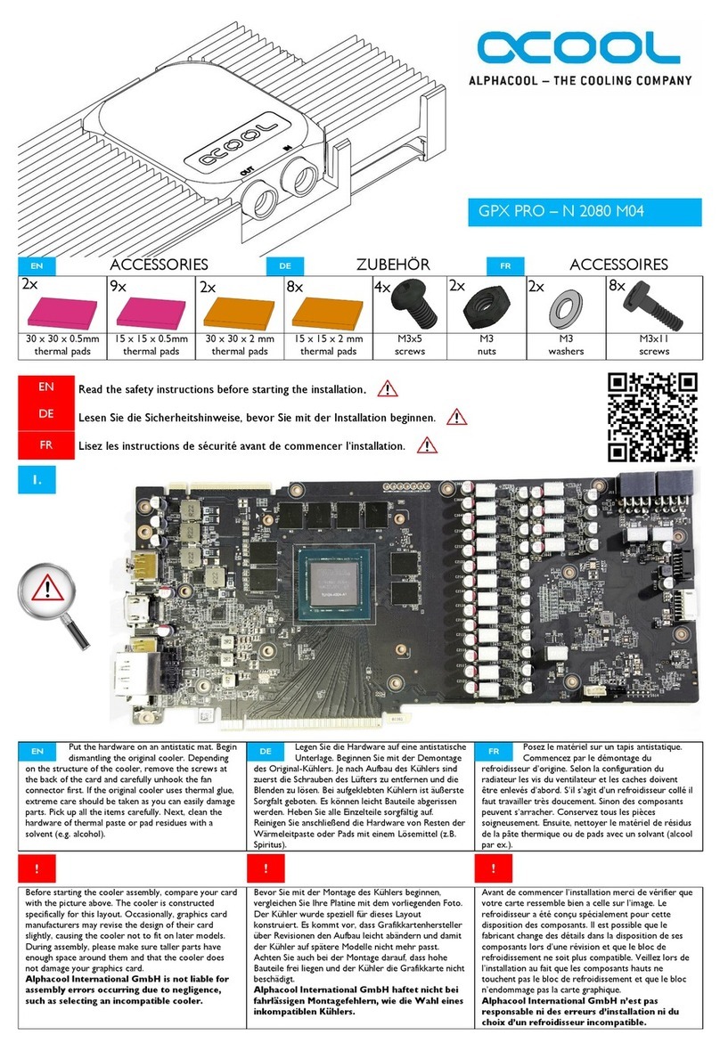
STR-V SVRE-D032SA Series User manual

3.5” Form Factor Mirror Drive
Serial-ATA MODEL
SVRE-D032SA Series
User’s Manual
P/N A204377
Revision 1.0

3.5" Form Factor Mirror Drive SATA Model User's Manual
Introduction
Thank you for selecting the 3.5” Form Factor Mirror Drive SVRE-D032SA Series Serial-ATA Model.
This manual describes the proper installation procedures, operation and maintenance of your SATA
Mirror Drive, and will help you familiarize with its features.
Hereinafter, Serial-ATA will be referred as SATA and SVRE-D032SA as SATA Mirror Drive respectively.
NOTE
Please be sure to read first the user's manual before using your SATA Mirror Drive.
This manual describes the basic precautions, handling methods, setting methods for various functions,
etc. so that you can maximize the performance of the mirror drive.
If you encounter any problems with your mirror drive, please refer to this instruction manual before
contacting the support desk as described at the end of this manual. "6 Troubleshooting" section
describes the solutions to the most common problems that might occur while using the mirror drive.
PACKAGING MATERIALS
The original packaging materials protect the SATA Mirror Drive from damage during shipment.
After unpacking the SATA Mirror Drive, please retain the packaging materials in case you need to ship
the SATA Mirror Drive in the future.
In addition, this product is sealed in an antistatic and moisture-proof bag before shipping. Open the bag
only when you are ready to set it up.
RECORDING THE PRODUCT NAME, VERSION & SERIAL NUMBER
Before installing the SATA Mirror Drive to the host computer, please jot down the model name, version,
and serial numbers in the spaces provided for at the last page of this user’s manual. Keep the
information for record purposes.
Refer to Section " 2.1 Part Names " for the location of the model name, version, and serial number.
x WE HAVE MADE EVERY EFFORT TO ENSURE THE ACCURACY AND COMPLETENESS
OF THIS DOCUMENT. IF YOU FIND INACCURACIES OR OMISSIONS, PLEASE CONTACT
YOUR DISTRIBUTOR.
Copyright© Storage Vision Co., Ltd. 2020 All rights reserved.
x THE CONTENTS OF THIS DOCUMENT ARE SUBJECT TO CHANGE WITHOUT NOTICE.
x THIS DOCUMENT MAY NOT BE REPRODUCED OR COPIED IN WHOLE OR IN PART.
i

3.5" Form Factor Mirror Drive SATA Model User's Manual
To ensure the safe use of this product:
This user's manual uses the following symbols to highlight the important points related to the safe use of
this product. Please observe all safety information as indicated.
SAFETY SYMBOLS
To protect against personal injury and product damage, the following symbols are used throughout this
manual to highlight safety information.
Warning Indicates a potentially hazardous situation that may result in death or
serious injury to the user or severe damage to the product.
Caution Indicates a potentially hazardous situation that may result in serious
injury to the user or damage to the product.
Important Indicates important information wherein failure to observe may result
to improper product function.
WARNING / CAUTION LABELS
Labels with black lettering against a yellow background affixed either to the exterior or interior of the
product are Warning or Caution labels that provide important safety information. Observe all the
directions given on these labels.
In cases where Warning or Caution labels can be found aside from those written in the manual, be sure
to follow the directions as mentioned.
ii

3.5" Form Factor Mirror Drive SATA Model User's Manual
Warning
z If you detect any abnormal conditions, such as smoke or foul odors, turn off immediately the power
of the host computer.
It may cause fire, electric shock or damage.
z If any foreign substance or material (metal, water, liquid, etc.) seeps into the SATA Mirror Drive,
turn off immediately the power of the host computer.
It may cause fire, electric shock or damage.
z Do not use the SATA Mirror Drive in a high temperature or high humidity environment.
It may cause fire, electric shock or damage.
z Do not disassemble or modify this product. STR-V cannot guarantee the performance or safety of
any product that has been repaired by the customer or by an unauthorized third party.
It may cause fire, electric shock or damage.
z Be sure to turn off first the power of the host computer and any other connected devices before
connecting or disconnecting the cables. Also, to avoid putting excessive stress on the printed circuit
board of the SATA Mirror Drive, push or pull the connector only along the axis perpendicular to the
board.
It may cause fire, electric shock or damage.
iii

3.5" Form Factor Mirror Drive SATA Model User's Manual
Caution
z Do not use the SATA Mirror Drive in locations wherein it will be subjected to vibration or shock
exceeding the specifications.
It may cause a malfunction or disk failure.
z Rapid temperature change may cause condensation. Do not use the SATA Mirror Drive in an
environment or location that is susceptible to condensation.
It may cause a malfunction or disk failure.
If you think condensation has occurred, allow the SATA Mirror Drive to acclimate to the new
environment and make sure that it is completely dry before using it.
z Do not place the SATA Mirror Drive near electronic devices that generates strong electromagnetic
fields, such as televisions or loudspeakers.
It may cause a malfunction or disk failure.
z Turn off the power before moving the unit enclosing the SATA Mirror Drive to avoid vibration or
shock.
It may cause a malfunction or disk failure.
z If the power is turned on and off repeatedly for a short period of time, this may damage the spindle
motor and head of the drive which may shorten its service life. If you turn off the power, wait some
time (about 15 seconds) for the media inside the drive unit to stop before turning it on again.
When removing a drive unit for replacement, turn off the power and wait for at least 20 seconds
before pulling it out to avoid malfunction or failure.
z Do not leave or store the product for a long period of time (3 months or more) without energizing it.
It may cause a malfunction or disk failure.
z Avoid applying excessive pressure to the cover of the drive unit.
It may cause a malfunction or disk failure.
z After unpacking from transport, ensure first that each disk drive is properly inserted before turning
on the power. Refer to Section " 3.4 Turning On The Power "
(
iv

3.5" Form Factor Mirror Drive SATA Model User's Manual
Important
z Back up all important data stored in the SATA Mirror Drive to a suitable storage medium such as
tape drive or optical medium. The Mirror Drive’s mirroring technology prevents data loss even if
one drive unit fails. However, if two drive units fail at the same time or if a non-redundant component
fails, data loss may still occur. Additionally, accidental deletion of data or equipment damage may
also result in data loss
z Do not block the hole ventilation on the surface of the HDD. Lack of cooling airflow may lead to hard
disk drive failure or malfunction.
z The cache memory of the installed drives is enabled (as default factory setting). Except in
emergencies, make sure to follow the operating system's proper shutdown procedure or wait at
least 10 seconds after the access indicator has stopped flashing before turning off the power.
Failure to do so may result in loss of data in the drive’s cache memory.
z Each drive unit is managed through serial number. Do not remove or exchange the drive units,
except only when replacing a failed controller unit or drive unit. It may result in a boot up failure of
the host computer
z Use the mounting screws provided to firmly secure the SATA Mirror Drive in the mounting bay
inside the host computer (0.49 Nm torque is recommended)
v

3.5" Form Factor Mirror Drive SATA Model User's Manual
Handling Static-Sensitive Device
To prevent damage to components due to static electricity, please observe the following precautions
when handling this product.
z Before handling the SATA Mirror Drive or other static-sensitive devices, touch a metal object, such
as the metal enclosure of the host computer, to discharge any static electricity from your body.
z Handle the SATA Mirror Drive carefully by holding it at the edge of its housing. Never touch the
circuit board or any exposed circuitry.
z When replacing the controller unit or drive unit, or when placing the SATA Mirror Drive in another
location after opening the product, use the antistatic moisture-proof bag used in wrapping the
product during shipment. Place it on a flat level surface. Use this as your SATA Mirror Drive
working area.
vi

3.5" Form Factor Mirror Drive SATA Model User's Manual
Important Points During Mirror Drive Installation
Install the product in a horizontal position as shown in the figure below (the inclination with the horizontal
plane is within 5 degrees).
Gently push the drive unit to
make sure that it has been
securely mounted
Gravitational Direction
vii

3.5" Form Factor Mirror Drive SATA Model User's Manual
Table of Contents
Introduction ..........................................................................................................................................................i
To ensure the safe use of this product:...............................................................................................................ii
Warning.............................................................................................................................................................. iii
Caution ..............................................................................................................................................................iv
Important.............................................................................................................................................................v
Handling Static-Sensitive Device.......................................................................................................................vi
Important Points During Mirror Drive Installation.............................................................................................. vii
Table of Contents............................................................................................................................................. viii
13.5” Form Factor Mirror Drive Introduction................................................................................................. 10
1.1 Features.............................................................................................................................................. 10
1.2 Mirroring.............................................................................................................................................. 10
1.3 Data Reconstruction ............................................................................................................................11
1.4 Revival Reconstruction ........................................................................................................................11
2Outline Figure ............................................................................................................................................. 12
2.1 Part Names ......................................................................................................................................... 12
2.2 External Dimensions........................................................................................................................... 13
2.2.1 SATA Mirror Drive................................................................................................................... 13
2.2.2 5-inch Bay Mirror Drive Installation Fitting ............................................................................. 14
2.2.3 Drive Unit ............................................................................................................................... 14
3Connecting To Host Computer ................................................................................................................... 15
3.1 Operation Mode Setting...................................................................................................................... 15
3.2 Mounting in the Host Computer .......................................................................................................... 15
3.3 Cable Connection ............................................................................................................................... 16
3.4 Turning On the Power......................................................................................................................... 16
4Settings....................................................................................................................................................... 17
4.1 DIP Switch .......................................................................................................................................... 17
4.1.1 Host Side SATA Speed Setting (Dip Switch: 4)...................................................................... 17
4.1.2 Drive Write Cache Setting (Dip Switch: 6) ............................................................................. 17
4.1.3 Revival Reconstruction Setting (Dip Switch: 7) ..................................................................... 18
4.1.4 Buzzer Setting (Dip Switch: 9) ............................................................................................... 18
5Status Display............................................................................................................................................. 19
5.1 LED Display ........................................................................................................................................ 19
5.1.1 Access LED............................................................................................................................ 19
5.1.2 Drive LED............................................................................................................................... 19
5.2 LED & Buzzer Status Display Examples............................................................................................. 20
6Troubleshooting .......................................................................................................................................... 21
6.1 Failure Status Checking...................................................................................................................... 21
6.2 Replacing A Drive Unit ........................................................................................................................ 22
6.2.1 Replacement of One Drive Unit ............................................................................................. 23
6.2.2 Replacement of Both Drive Units........................................................................................... 24
viii

3.5" Form Factor Mirror Drive SATA Model User's Manual
ix
6.3 Controller Unit Replacement............................................................................................................... 25
6.3.1 When both drive units are functioning normally..................................................................... 26
6.3.2 When one drive unit has failed............................................................................................... 26
6.4 Other problems ................................................................................................................................... 27
Appendix-A Specifications ............................................................................................................................... 28
Appendix-B Accessories .................................................................................................................................. 29
Appendix-C Default Factory Setting ................................................................................................................ 30
Appendix-D Replacement Parts ...................................................................................................................... 31
Inquiries ........................................................................................................................................................... 32

3.5" Form Factor Mirror Drive SATA Model User's Manual
1 3.5” Form Factor Mirror Drive Introduction
The 3.5” Form Factor SATA Mirror Drive utilizes two SATA 2.5-inch Hard Disk Drives and uses
mirroring technology to safeguard data and to provide uninterrupted operation.
Since the host computer will recognize the SATA Mirror Drive as a standard SATA HDD, installing the
SATA Mirror Drive simply involves connecting it to a SATA cable from the host computer
1.1 Features
z The 3.5” form factor makes the SATA Mirror Drive easy and convenient to install that will improve
the reliability of the Host system and allows continuous operation for a long time (SVRE-D032SA /
SA1).
Moreover, there is also a separate model that can be installed in a 5.25” open drive bay (half-height) and
have an easy front access (SVRE-D032SA / SA1-B).
z Even if one drive unit fails, the SATA Mirror Drive will continue to function and no data is lost. When
the failed drive unit is replaced with a new one, data will be rebuilt automatically.
z The SATA Mirror Drive uses the industry standard Serial ATA interface and can be used like any
other standard SATA HDD. No special device drivers will be needed and can be used on any host
computer or operating system.
z Conforms to Serial ATA Interface ATA/ATAPI-7 Specifications (maximum data transfer rate: 6Gbps)
It also has a Dip-switch selectable operation mode and function that allows the host side to be
configured as either 6Gbps or 3Gpbs.
z Mirroring technology (RAID Level 1) is implemented via hardware thereby minimizing any overhead
on the system side
1.2 Mirroring
Mirroring technology writes the same data to two drive units simultaneously. If one drive unit fails, data
can still be accessed and read from the other drive unit.
10

3.5" Form Factor Mirror Drive SATA Model User's Manual
1.3 Data Reconstruction
Data rebuilding (the copying of all data from the fully functional drive unit to the new replacement drive
unit) will start automatically and the Mirror Drive is fully usable even if the rebuild process ongoing.
During data rebuild, the drive status indicator of the fully functional drive unit will light green while the
drive status indicator of the replacement drive unit will flash orange.
Also, if the Mirror Drive is rebooted while the data rebuild is in progress, rebuilding will not resume from
the start but from the block prior to the last completed block recorded.
(Refer to「5.1 LED Display」for more information)
Caution
Please make sure to perform the proper shutdown procedure if you want to turn
off the host computer while the SATA Mirror Drive is still rebuilding the data.
Failure to do so may cause the data of the normal drive unit to be corrupted and
rebuilding may not be completed.
When a sector of the fully functional drive unit could not be read during data reconstruction, the SATA Mirror
Drive skips copying that bad sector and continues to reconstruct the remaining data. These skipped sectors
will no longer be readable. However, once another data is written to that sector, it can be read correctly again.
Important
If the data reconstruction process skips any sector during data rebuilding, the
data on this sector will be lost.
Therefore, periodic backup is recommended
1.4 Revival Reconstruction
When something goes wrong in a drive unit and the mirror controller cannot get a response from the
drive within the specified time (30 seconds), the controller will issue a reset command to the drive to
check its status (Background Retry).
If the drive is recovered, the SATA Mirror Drive returns to the normal operation. But if it is not, the SATA
Mirror Drive will shift to revival reconstruction mode.
Revival Reconstruction turns the power of the appropriate drive OFF/ON and if the drive status becomes
ready, reconstruction is automatically started. The SATA Mirror Drive will still respond to the host
normally even during reconstruction. Once reconstruction is completed, the SATA Mirror Drive returns
to normal mode automatically
Revival reconstruction is executed up to two times. On the third time, it will not proceed with the data
rebuild process and will treat the drive as a failed drive. The failed drive status indicator (LED) of the
corresponding drive will light orange.
The revival reconstruction setting function can be Enabled/Disabled by Dip Switch. The default factory
setting is “Enabled”,
(See「4.1.3 Revival Reconstruction Setting」for more information)
11

3.5" Form Factor Mirror Drive SATA Model User's Manual
2 Outline Figure
2.1 Part Names
DRV1
M
A
I
N
C
A
R
D
S
U
B
C
A
R
D
4-#6-32UNC
取付け用ネジ穴(4箇所)
CN2
PWR
P15
S7S7 P1P1
P1
P15P15
CN3
1
ON
S1S1
ユニファイ並目ネジ
1
2
Status Si
g
nal Connecto
r
SATA Connector
(
Host Interface
)
External LED Status Si
g
nal Connecto
r
Power Connecto
r
Buzzer Sto
p
Si
g
nal Connecto
r
A
CCESS LED
DRIVE 2 LED
DRIVE 1 LED
Controller Unit
Mountin
g
Screw Holes
(
x4
)
4- #6-32UNC
Unified Coarse Screw
Drive Interface
DIP Switch Mountin
g
Screw Holes
(
x3
)
4- #6-32UNC
Unified Coarse Screw
Same for Both Sides
SVRE-D***SA* ← Model Name
EC: YB**** ← Version
S/N: ********* ← Serial number
12

3.5" Form Factor Mirror Drive SATA Model User's Manual
2.2 External Dimensions
2.2.1 SATA Mirror Drive
<SVRE-D032SA/SA1>
147
41.6
44.5
146
P15
P1
PWR
CN2
P1 P15
CN3
S7S7 P15
P1
S1S1
28.5
Buzzer
ON
1
対面も同様
4-#6-32UNC
ユニファイ並目ネジ
取 所)付け用ネジ穴(3箇
41.28
3.2
60
101.6
1
2
6.35
(15.9)
25.4
DRV1
95.2
(60.2)
3.2
ユニファイ並目ネジ
取付け用ネジ穴(4箇所)
UNC4-#6-32
Mountin
g
Screw Holes
(
x4
)
4- #6-32UNC
Unified Coarse Screw
Mountin
g
Screw Holes
(
x3
)
4- #6-32UNC
Unified Coarse Screw
Same for Both Sides
Unit: mm
13

3.5" Form Factor Mirror Drive SATA Model User's Manual
2.2.2 5-inch Bay Mirror Drive Installation Fitting
<SVRE-D032SA/SA1-B>
147
79.2
52.5
11.99.9
43
OFF
Buzzer
ON
146
2
1
DRV1
S1S1
CN3
S7S7
1
ON
P1P1
PWR
CN2
P15P15
P1
P15
Mounting Screw Holes (x4)
4- #6-32UNC
Unified Coarse Screw
Same for Both Sides
Unit: mm
2.2.3 Drive Unit
87.8
69.9
90.6
95
10.5
3
9.5
14
Unit: mm
14

3.5" Form Factor Mirror Drive SATA Model User's Manual
3 Connecting To Host Computer
3.1 Operation Mode Setting
Refer to 「4 Settings」for the various settings of the DIP switch. For the default factory settings, refer to
「Appendix C: Factory Default Setting」.
3.2 Mounting in the Host Computer
Use the provided mounting screws into the specified mounting holes when assembling into the host
computer. Refer to sample figures below when using the side mounting screw holes
Mountin
g
Scre
w
Mountin
g
Scre
w
Refer to「4.1.4 Buzzer Setting」
Mountin
g
Scre
w
Mountin
g
Scre
w
Mountin
g
Scre
w
Mountin
g
Scre
w
Mountin
g
Scre
w
Mountin
g
Scre
w
When Using the Side Mounting Screws
Caution
When installing into the host computer, provide sufficient cooling in
order to ensure that the surface temperature of the drive unit remains
below 60°C.
15

3.5" Form Factor Mirror Drive SATA Model User's Manual
3.3 Cable Connection
1. The power supply uses DC +5V only. Connect the power cable to the power connectors of both the
main card and sub card. The sub card connection must come from a separate cable as that of the main
card but from the same power supply.
(Refer to「2.1 Part Names」for the location of the connectors)
2. Connect the SATA signal cable to the SATA connector and before connecting to the host computer.
(Refer to「2.1 Part Names」for the location of the connectors)
Caution When setting the switches and attaching the cables, ensure first that
the power supply of the host computer is turned off.
3.4 Turning On the Power
Before turning on the host computer, press lightly the front face of each drive unit to confirm that these
are firmly inserted and verify if the lever has locked in.
Next, turn on the host computer’s main power supply and check if the host computer detects the unit
correctly.
Gently push the drive unit to
make sure that it has been
securely mounted.
Caution Before turning on the host computer, make sure that both the Signal
and power cables are attached properly.
16

3.5" Form Factor Mirror Drive SATA Model User's Manual
4 Settings
4.1 DIP Switch
The DIP Switch can be used to change the settings of SATA Speed (Host Side), Write Cache mode of
the installed drive, Revival Reconstruction and Buzzer Features of the SATA Mirror Drive. Except with
the Buzzer, please turn off the power before changing the Dip Switch setting.
12
3
4
5678
9
0
O
N
DIP Switch Functions Default Shipment
Setting
4 Host Side SATA Speed Setting 6Gbps
6 Drive Write Cache Write Back
7 Revival Reconstruction Enabled
9 Buzzer Enabled
Important
Do not change the setting of Dip Switch # 1, 2, 3, 5, 8 & 0.
Please note that making changes in any of these may result in the loss of stored
data.
4.1.1 Host Side SATA Speed Setting (Dip Switch: 4)
Host side speed can be set to 6Gpbs or 3Gbps.
4.1.2 Drive Write Cache Setting (Dip Switch: 6)
When the Dip Switch is OFF, the mounted Drive operates in write-back mode (Cache Function Enabled).
When it is set to ON, the drive operates in write-through mode (Cache Function Disabled).
Important
Always observe the shutdown procedure specified for the host computer’s
operating system. Except during emergency, try to wait at least 10 seconds
to be sure that both the access LED and the drive LEDs have stopped
flashing before shutting off the power. Turning off the power while the access
LED or the drive LED is still lighting may result in loss of data currently
located in drive’s cache memory.
17

3.5" Form Factor Mirror Drive SATA Model User's Manual
4.1.3 Revival Reconstruction Setting (Dip Switch: 7)
When Revival Reconstruction is enabled, the SATA Mirror Drive will attempt to do data reconstruction
even if the cause of error to the drive is determined to be unrecoverable. The SATA Mirror Drive will not
remain in Degraded Mode but instead, will automatically try to revive the drive up to two times.
If it is disabled, the drive will not be revived and will be treated as a failed drive and the SATA Mirror
Drive will enter into Degraded Mode.
4.1.4 Buzzer Setting (Dip Switch: 9)
If the Buzzer is enabled, the buzzer will sound when Drive 1 or Drive 2 fails or the SATA Mirror Drive is
in System Halt state. In the event of a drive unit failure, the buzzer will continue to sound until the failed
drive unit is replaced. The buzzer can be stopped if the switch position is changed to disable setting.
Make sure to return the buzzer back to Enabled position after the failed drive unit has been replaced.
If the Buzzer is disabled, the buzzer will not emit any sound at all.
When using an external bracket for the 5" Drive Bay installation, please make sure that Dip Switch 7 is
set to enable. The buzzer sound can be turned ON and OFF through the Buzzer switch in the external
bracket. If the buzzer is turned OFF prior to drive replacement, slide it back to ON after the new drive unit
has been inserted
18

3.5" Form Factor Mirror Drive SATA Model User's Manual
5 Status Display
5.1 LED Display
The status of the controller unit and the drive unit is indicated by the LED on the front.
5.1.1 Access LED
Display Description
Green
<1> When the power is turned on. (*1)
<2> Processing a command from the host computer.
Either of the above.
Orange Controller unit failure.
Orange
Flashing
<1> When both drive units have failed or both drive units are not correctly
inserted.
<2> When the configuration information of the controller unit, Drive 1 unit
and Drive 2 unit are all different from each other.
(Both drive status indicators show green simultaneously.)
<3> When one drive unit has failed and the fully functional drive unit has
been erroneously replaced or both drive units have been replaced.
(Both drive status indicators show green simultaneously.)
Any of the above.
(*1) When the power is turned on, both the access indicator drive status indicators lights up green.
When SATA Mirror Drive boot up process is complete, all will be turned off.
5.1.2 Drive LED
Display Description
Green
<1> When the power is turned on. (*1)
<2> Processing a command from the host computer.
<3> Then SATA Mirror Drive is processing an internal command.
Either of the above
Orange <1> Drive unit failure
Orange
Flashing
Target drive unit of data rebuilding. (*2)
(Source drive unit LED is green at the same time)
(*1) When the power is turned on, both the access indicator drive status indicators lights up green.
When SATA Mirror Drive boot up process is complete, all will be turned off.
(*2) Drive Status Indicator will go out after data rebuilding.
Important
If the drive status indicator lights orange, replace immediately that drive unit.
Leaving the SATA Mirror Drive with a failed drive unit will result in data loss
if the other drive unit will also fail.
19
This manual suits for next models
2
Table of contents

