9
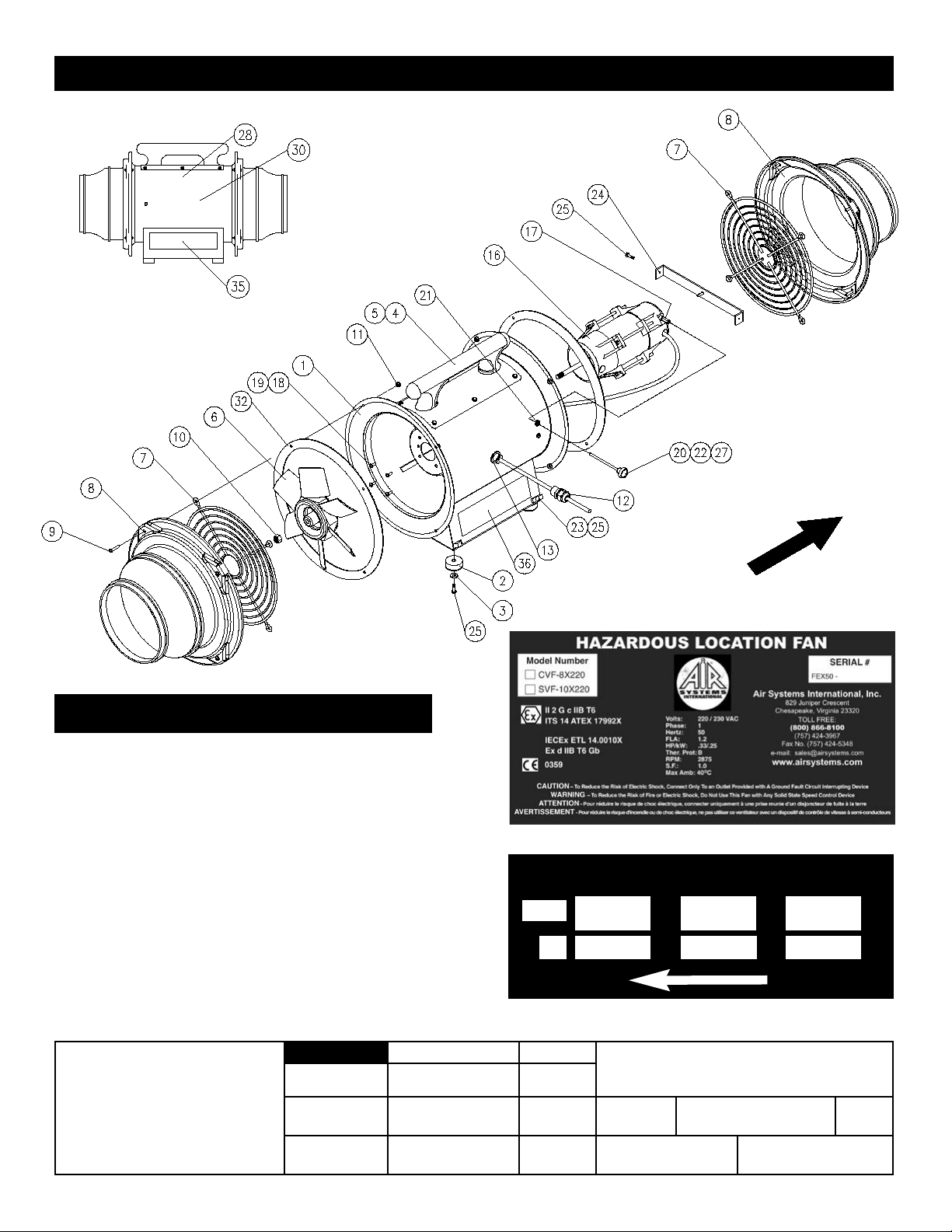
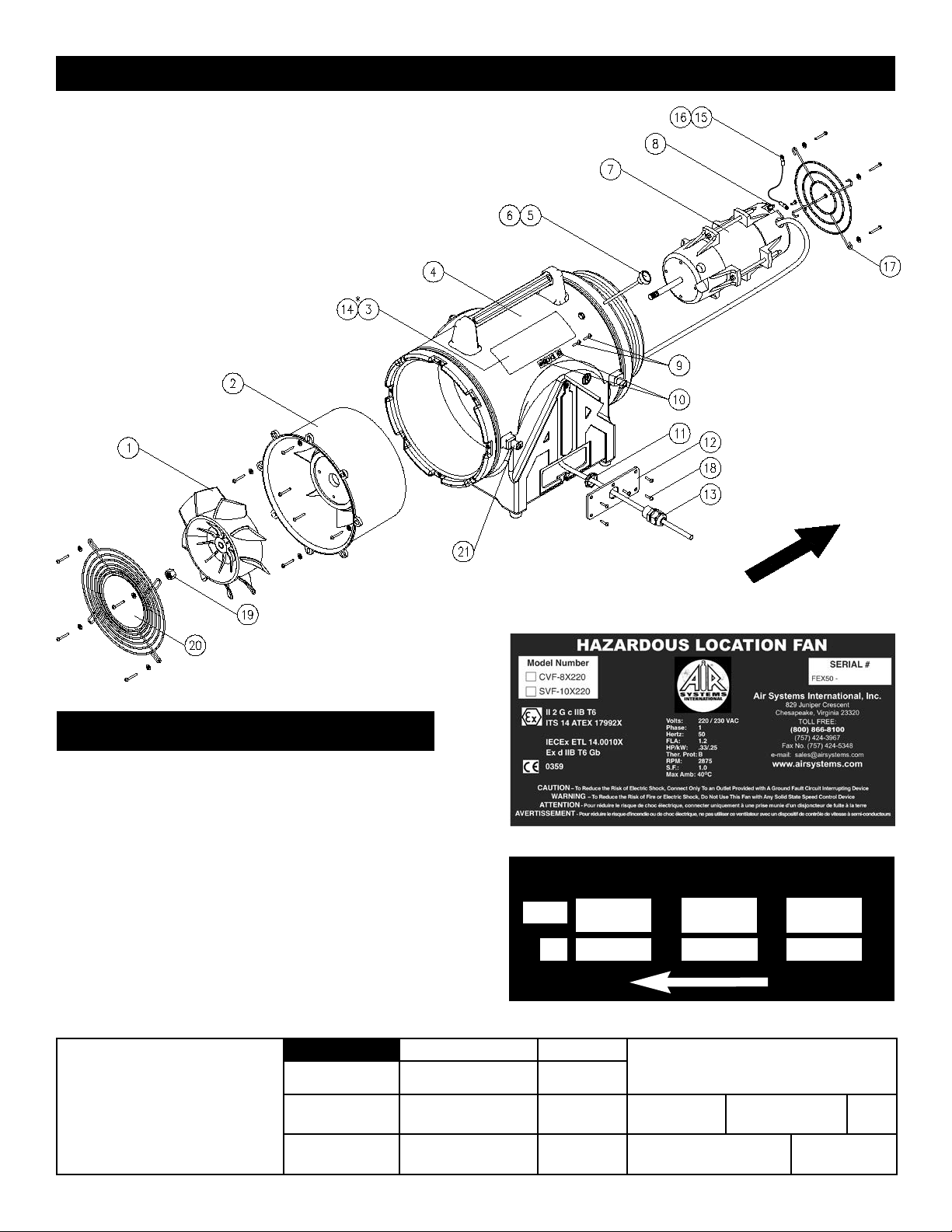
System Components: Model SVF-10X220
SEQ. # ITEM # DESCRIPTION BOM QUANTITY
1 MILF-10BR 10” STEEL BASE - RED, AXALTA, P/N RED RIVER HP II 1
2 HDWR026 RUBBER FEET FOR SVF FANS - 70 DURO SBR 4
3 FW3/16 3/16 USS FLAT WASHER ZINC COATED STEEL 4
4 FS10X050W 10-24 X 1/2 HEX WASHER, ZINC COAT STEEL 6
5 SVF-10HNDL HANDLE, BLACK, LLDPE, EXXON P/N LL8555 1
6 SVF-FAN AXIAL FAN, REINFORCED FIBER, WINGFAN P/N PACAS 1
7 MGDAXFAN1 FINGER GUARD, ZINC COATED STEEL 2
8 SVF-108ADP 10” TO 8” SHROUD, BLACK, LLDPE, EXXON P/N LL8555 2
9 FS1032X78T 10-32 X 7/8 TRUSS,PHILLIPS, ZINC COATED 8
10 FNM8X1ESN M8 X 1.0 ELASTIC STOP NUT, ZINC COATED 1
11 FN1032ESN 10-32 ELASTIC STOP NUT ZINC COATED 8
12 ELA001 CABLE GLAND, 5-12mm, ALTECH P/N 5308921 1
13 ELA007 1/2 CONDUIT LOCK NUT, ZINC COATED STEEL 1
16 MTR043EX22 ATEX APPROVED MOTOR,220-230 VAC,50 HZ 1
17 HDWR068 COUPLING NUT 10-24 X 3/4 LONG,GRADE 2 1
18 FS1032X050 10-32 X .5, ROUND PHILLIPS HEAD, ZINC 4
19 FW10LOCK #10 LOCKWASHER ZINC COATED 4
20 FS10X350TS 10-24 X 3-1/2 FULLY THREADED STEEL STUD 1
21 HDWR027 GROMMET FOR SV FANS-60 DURAMETER, SBR 1
22 HDWR070 BLACK ABS KNOB WITH 10-24 THREADS, SVF 1
23 ELA051 ALUMINUM GROUNDING LUG, 6-14 AWG (6.35mm MAX) 2
24 MBSVF10EXP STABILIZER BRACKET FOR SVF-10EX SERIES, STEEL 1
25 FS10X075W 10-24 X 3/4 HEX WASHER, ZINC COATED 6
27 ELA039 1/4” DIAMETER SHRINK TUBING, PVC 0.25
28 DECAL045 MOTOR ROTATION DECAL, PERMANENT OUTDOOR 2
30 DECAL043 AIR SYSTEMS WORLD LOGO DECAL - 4” DIA. 1
32 ILF-G GASKET, ROUND, 8 HOLES, FOR SVF FANS, SBR 2
35 DECAL168 SERIAL NO. DECAL,CVF-8X220,SVF-10X220 1
36 DECAL169 PERF. SPEC. DECAL, CVF-8X220, SVF-10X220 1