AIR SYSTEMS INTERNATIONAL SVF-8AC Manual

OPERATING INSTRUCTIONS AND REPLACEMENT PARTS
Models: SVF-8AC, SVF-6ACAN, SVF-15ACAN, SVF-25ACAN
SVF-8DC, SVF-6DCAN, SVF-15DCAN, SVF-25DCAN
AIR SYSTEMS INTERNATIONAL, INC.
829 Juniper Crescent, Chesapeake, Va, 23320
Telephone (757) 424-3967
Toll Free 1-800-866-8100
Fax No. (757) 424-5348
www.airsystems.com.
e-mail: [email protected]
This manual must be read carefully and followed by all persons who have or will have the responsibility
for using or servicing this equipment. This equipment will perform as designed only if used according
to the instructions. Otherwise it could fail to perform as designed, causing personal injury or death.
WARNING

Typical Saddle Vent® Setup Procedure
Place fan or blower a minimum of
5 ft. (1.6m) from manhole opening
Blower or Fan
90° Elbow
Manhole
Opening
Manhole Lid
Universal Mount
Saddle Vent®
Select a blower or fan based on environmental
conditions and the size of the con ned space.
For information or guidance in selecting the
proper set-up, please contact Customer Service.
STEP 1) Install 6 ft. (1.8m) duct on blower or fan
STEP 2) Install 90° elbow on top of Saddle Vent®
STEP 3) Install duct on bottom of Saddle Vent®
STEP 4) Install universal mount on Saddle Vent® and
set in place with manhole lid for support
STEP 5) Install duct from blower to 90° elbow
STEP 6) Turn on blower or fan
Warning: For explosive environments,
follow ANSI/API 2015 and 2016 procedures
The Saddle Vent® is a registered trademark of Air Systems International, Inc.
The Conductive Saddle Vent® is covered by U.S. and Foreign Patents
WARNING: HAZARDOUS LOCATION OPERATIONS
Use an explosion-proof or intrinsically safe blower or fan,
conductive ducting, and The Conductive Saddle Vent® System.
Attach all grounding wires and assure a complete circuit to the
blower or fan in order to remove static charges.
The Saddle Vent® Ventilation System
All ventilation procedures should comply with federal, state, and local regulations. Air quality should be tested prior to
ventilating a con ned space. A purge chart is provided on our website, www.airsystems.com, help assist in estimating the
approximate time needed to ventilate con ned spaces. Air quality should be tested continuously during con ned space
occupancy to ensure a stable atmosphere and worker safety because atmospheric conditions can change rapidly. Addi-
tional procedures and recommendations are available from federal, state, and local agencies. DO NOT operate these fan
unit in a vertical position or with the ange or guards removed.
Note: If volatile or explosive vapors are suspected, use Air Systems’ explosion proof electric blower, Model No. SVB-
E8EXP, explosion proof in-line fan, Model No. SVF-10EXP, explosion proof contractors fan, Model No. CVF-8EXP or Air
Systems’ intrinsically safe pneumatic blower, Model No. SVB-A8.
Note: For con ned space ventilation in non-hazardous locations, use Air Systems’ con ned space ventilation kit, Model
SV-CUP. For hazardous locations use ventilation kit, Model SV-CUPCND along with one of the above explosion proof
blowers or fans.
SAFETY PRECAUTIONS
READ AND FOLLOW ALL INSTRUCTIONS BELOW
WARNING
Fan and blower models with the “EX” or “X” designation are the
only models approved for use in hazardous locations. These
models are NOT approved for use in mines.
2

All ventilation procedures should comply with federal, state, and local regulations. Air quality should be tested prior to
ventilating a con ned space. A purge chart is provided on our website, www.airsystems.com, help assist in estimating the
approximate time needed to ventilate con ned spaces. Air quality should be tested continuously during con ned space
occupancy to ensure a stable atmosphere and worker safety because atmospheric conditions can change rapidly. Addi-
tional procedures and recommendations are available from federal, state, and local agencies. DO NOT operate these fan
unit in a vertical position or with the ange or guards removed.
Note: If volatile or explosive vapors are suspected, use Air Systems’ explosion proof electric blower, Model No. SVB-
E8EXP, explosion proof in-line fan, Model No. SVF-10EXP, explosion proof contractors fan, Model No. CVF-8EXP or Air
Systems’ intrinsically safe pneumatic blower, Model No. SVB-A8.
Note: For con ned space ventilation in non-hazardous locations, use Air Systems’ con ned space ventilation kit, Model
SV-CUP. For hazardous locations use ventilation kit, Model SV-CUPCND along with one of the above explosion proof
blowers or fans.
SAFETY PRECAUTIONS
READ AND FOLLOW ALL INSTRUCTIONS BELOW
WARNING
Fan and blower models with the “EX” or “X” designation are the
only models approved for use in hazardous locations. These
models are NOT approved for use in mines.
3

4
1) Place fan in a clean, fresh air environment.
2) Air quality of the conned space should be tested prior to ventilation. If air quality of the conned space is
unacceptable, consult a trained professional.
3) Inspect fan for damaged or worn parts, and inspect ducting for air leaks prior to fan operation.
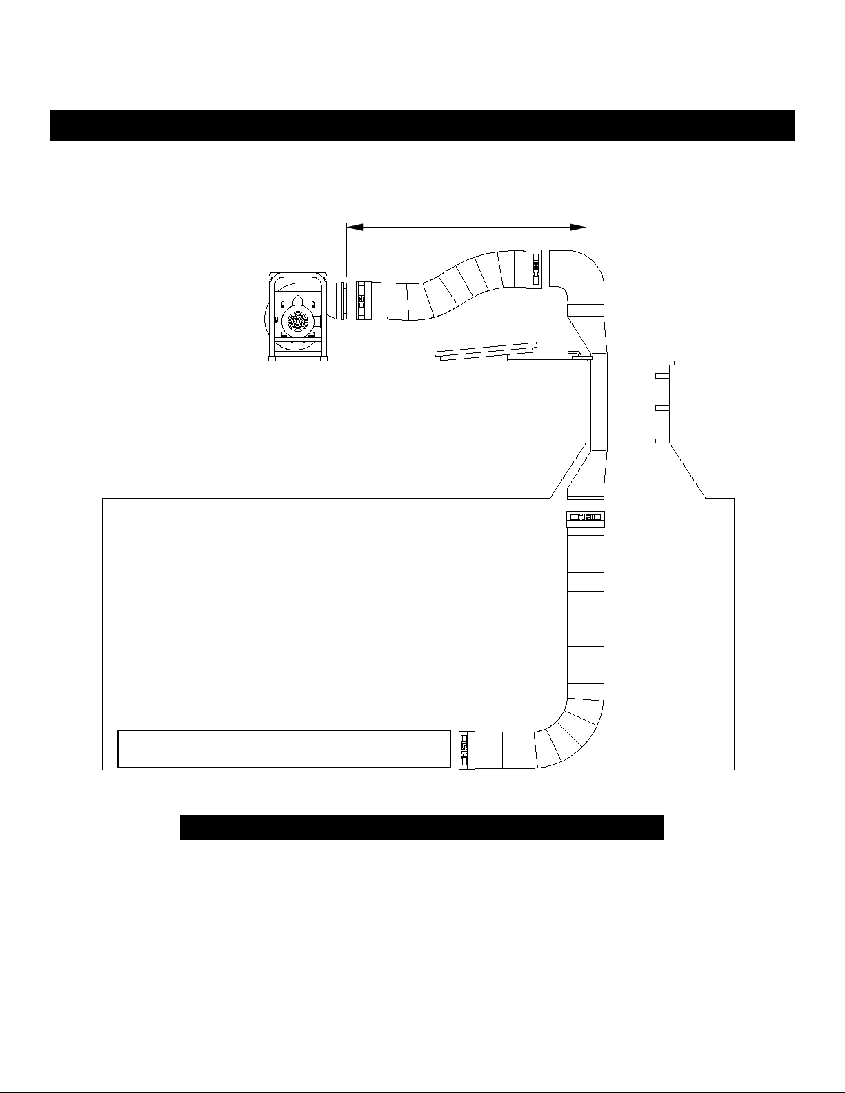
4) Install duct cuff to exhaust ange and secure. Keep bends and kinks in ducting to a minimum to maximimize
air ow. If canister model is used, secure canister with connect straps, open lid and pull out ducting. Inspect
for air leaks.
NOTE: Maximum recommended duct hose length is 25 ft.
5) Set fan upwind from the work location and a minimum of 5 ft. from the manhole opening.
6) Connect fan to power source.
DC versions require 12 VDC. Attach the red connector to the positive (+) terminal and the black conector to
the negative (-) terminal. This unit must be run in the positive pressure mode as this model is not approved
for extracting (sucking) air. DO NOT REVERSE WIRING.
WARNING: Vehicle electrical systems must be able to handle 15 amp service or electrical damage may occur.
AC versions require 115 VAC/60Hz (SVF-8AC), 15 amp service or 220 VAC/50Hz (SVF-8AC50).
NOTE: If an extension cord is required, the minimum recommended size is 14 AWG up to
25 ft. For further information refer to the National Electric Code Tables, Article 400.
7) Push ON/OFF switch to “I” position.
General Set-Up And Operation
For SVF-8AC And SVF-8DC Models
MOTOR TYPE 1/3 HP, 115 VAC/60 Hz (SVF-8AC), 2.6 amps, or 220VAC/50 Hz (SVF-8AC50)
Capacitor Start, Single Speed, 3200 RPM, CSA Approved
OUTLET SIZE 8” Diameter (203mm)
FLOW RATES
Free Air: 1275 cfm (2166 cm/hr)
15 ft. duct with one 90° bend: 797 cfm (1354 cm/hr)
15 ft. duct with two 90° bends: 677 cfm (1150 cm/hr)
Specications - AC Voltage Fans
MOTOR TYPE 1/6 HP, 13.5 VDC, 15 amps, Single Speed, 4200 RPM,
20 amp/32 VDC Slow Blow Fuse
OUTLET SIZE 8” Diameter (203mm)
FLOW RATES
Free Air: 1275 cfm (2166 cm/hr)
15 ft. duct with one 90° bend: 797 cfm (1354 cm/hr)
15 ft. duct with two 90° bends: 677 cfm (1150 cm/hr)
Specications - DC Voltage Fans

ITEM # DESCRIPTION PART #
1INTAKE GUARD MGDAXFAN1
2FAN SV-FAN-8MM
3 HANDLE HDWR056
4 115VAC 60Hz ELECTRIC MOTOR (SVF-8AC) SVF-8AC-MA
4A 220VAC 50Hz ELECTRIC MOTOR (SVF-8AC50) MTR043CN50
5 DISCHARGE GUARD MGDAXFAN2
6 ON/OFF SWITCH ELSW038R
7 POWER CORD ELCB012
8 CAPACITOR MTR043CNC
9 RUBBER FOOT HDWR026
10A 8” DIA.X 6’ LONG DUCT SVF-H6
10B 8” DIA. X 15’ LONG DUCT SVF-H15
10C 8” DIA. X 25’ LONG DUCT SVF-H25
11 DUCT CANISTER SVF-CAN
5
An optional GFI (Ground Fault Interrupter) cord/plug can be supplied to comply
with the 1996 NEC Code requirement: Section 305-6. Order P/N ELCB013.
System Components - AC Voltage Fans

6
ITEM # DESCRIPTION PART #
1INTAKE GUARD MGDAXFAN1
2FAN SV-FAN-8MM
3 HANDLE HDWR056
4 12 VDC ELECTRIC MOTOR WITH INLINE FUSE/FUSE HOLDER MTR044CN
5 20A 32 VDC IN-LINE FUSE ELF022
6 DISCHARGE GUARD MGDAXFAN2
7 ON/OFF SWITCH ELSW038R
8 POWER CORD ELCB045
9 RED BATTERY CLAMP ELA083R
10 BLACK BATTERY CLAMP ELA083B
11A BATTERY CONNECTOR FOR OPTIONAL BATTERY PACK (P/N BP-950) ELA127
11B 1 PAIR OF CONTACTS FOR ELA127 ELA126
12 RUBBER FOOT HDWR026
13A 8” DIA.X 6’ LONG DUCT SVF-H6
13B 8” DIA. X 15’ LONG DUCT SVF-H15
13C 8” DIA. X 25’ LONG DUCT SVF-H25
14 DUCT CANISTER SVF-CAN
System Components - DC Voltage Fans

7
PROBLEM POSSIBLE CAUSE SOLUTION
Excessive vibration
Air intake blocked Turn fan off and clear debris from intake.
Possible internal damage
Turn off and inspect fan blades, shaft, and housing
for debris, damage, and loose screws.
Note: Never run fan for extended periods without
installing duct on the exhaust ange.
Possible external damage Turn fan off and inspect for loose guards, broken
welds, etc.
Circuit breaker trips
SVF-8AC series only
Voltage output insuf cient Test outlet with volt meter.
Extension cord improperly sized Use 14 AWG extension cord up to 25 ft.
Faulty Capacitor Check and Replace with P/N MTRA089
Fan will not run
SVF-8DC only
Blown fuse (DC version only) Check and replace. Use only a 20A/32 VDC slow
blow fuse.
Battery connection
Ensure proper connection from battery clips to bat-
tery terminal posts. On battery pack units, recharge
battery.
Troubleshooting
Wiring Schematic - SVF-8AC-MA

Manual No. BLWR007
Rev. 6 September 2018
Air Systems’ manufactured equipment is warranted to the original user against defects in workmanship or materials under
normal use for one year from the date of purchase. Any part which is determined by Air Systems to be defective in mate-
rial or workmanship will be, as the exclusive remedy, repaired or replaced at Air Systems’ option. This warranty does not
apply to electrical systems or electronic components. Electrical parts are warranted, to the original user, for 90 days from
the date of sale. During the warranty period, electrical components will be repaired or replaced at Air Systems’ option.
NO OTHER WARRANTY, EXPRESSED OR IMPLIED, AS TO DESCRIPTION, QUALITY, MERCHANTABILITY, FIT-
NESS FOR A PARTICULAR PURPOSE, OR ANY OTHER MATTER IS GIVEN BY AIR SYSTEMS IN CONNECTION
HEREWITH. UNDER NO CIRCUMSTANCES SHALL THE SELLER BE LIABLE FOR LOSS OF PROFITS, ANY OTHER
DIRECT OR INDIRECT COSTS, EXPENSES, LOSSES, OR DAMAGES ARISING OUT OF DEFECTS IN, OR FAILURE
OF THE PRODUCT OR ANY PART THEREOF.
The purchaser shall be solely responsible for compliance with all applicable Federal, State and Local OSHA and/or MSHA
requirements. Although Air Systems International believes that its products, if operated and maintained as shipped from
the factory and in accordance with our “operations manual”, conform to OSHA and/or MSHA requirements, there are no
implied or expressed warranties of such compliance extending beyond the limited warranty described herein. Product
designs and speci cations are subject to change without notice. Rev. 2, 12/98
Air leaks are not covered under warranty except when they result from a defective system component, i.e. an on/off valve
or regulator or upon initial delivery due to poor workmanship. Air leaks due to poor delivery or damage will be covered un-
der delivery claims. Minor air leaks are part of routine service and maintenance and are the responsibility of the customer
just as are lters and oil changes.
Warranty
Other manuals for SVF-8AC
1
This manual suits for next models
7
Table of contents
Other AIR SYSTEMS INTERNATIONAL Fan manuals
Popular Fan manuals by other brands

LUCCI
LUCCI AIRFUSION BREEZE installation instructions

Craftmade
Craftmade ELLINGTON PAP52ABZ5RCDI installation guide

Honeywell
Honeywell HY108E operating instructions

DAYRON
DAYRON VERMONT 55W instruction manual

RenewAire
RenewAire BR70 SERIES Guide specifications

Fanimation
Fanimation distinction C1 series owner's manual