AIR SYSTEMS MACK-1 User manual

Operating Manual
Models
MACK-1, MACK-2, MACK-3,
MACK-NFPA1, MACK-NFPA3, MACK-NFPA3Q, &
MACK-1-6K, MACK-3TV & MACKNFPATV
Manual No. POA051
(Rev 4 April 2011)
Air Systems International MACK-1 Multi Air Command Kit
Air Systems International MACK-2 Multi Air Command Kit
Air Systems International MACK-3 Multi Air Command Kit
Air Systems International MACK-NFPA1 Multi Air Command Kit
Air Systems International MACK-NFPA3 Multi Air Command Kit
netzerotools.com
netzerotools.com
netzerotools.com

-2-
TABLE OF CONTENTS
Overview...........................................................................................................................................3
MACK-1 Setup, Operation & Parts Identification...................................................................4-5
MACK-2 Setup, Operation & Parts Identification...................................................................6-7
MACK-2 Filling Cylinders...........................................................................................................8-9
MACK-3 Setup & Operation for Common Air Sources, Parts Identification...................10-11
MACK-3 Setup & Operation for Isolated Air Sources.........................................................12-13
MACK-3 Setup & Operation for Optional Fill Whip Assembly MACK-3FA...................14-15
MACK-NFPA1 & MACK-NFPA3 Parts Identification.............................................................16
MACK-NFPA1 & MACK-NFPA3 Setup & Operation..............................................................17
Changing Cylinders.......................................................................................................................18
Shutdown Procedure......................................................................................................................18
High Pressure Airline General Maintenance & Inspection.......................................................18
Warranty Disclaimer......................................................................................................................19
netzerotools.com
netzerotools.com

-3-
OVERVIEW
The MACK series has been designed as a portable multifunctional air distribution system. All
MACK units are rated for 5000psi.
MACK-1
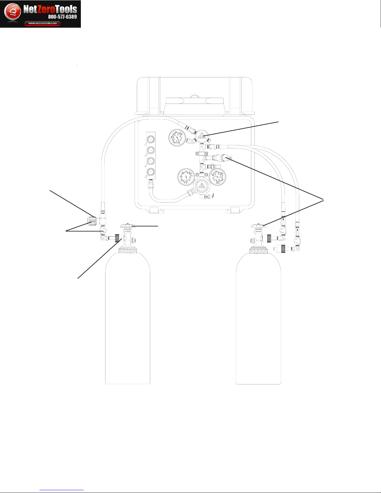
This version allows for one or two high pressure cylinders to be attached to the supply inlet
whips. A CGA-347 male inlet is provided for direct attachment to a bank of air cylinders. All
MACK series units have at least one air outlet manifold with pressure adjustments from 0-125psi.
MACK-2
This version has the same features as the MACK-1, with the addition of an adjustable fill regula-
tor, pressure gauge, and fill whip. An optional second fill whip is available.
MACK-3
The MACK-3 contains two independent low pressure manifolds and regulator systems that each
have their own cylinder supply hoses. An isolation valve is located between the regulators to
isolate the systems, as well as provide common air flow from a single bottled air source. One
regulator is set to provide low pressure air (0-125psi) for respirators, and one for medium pres-
sure air (0-250psi) for air shores and other rescue tools. This medium pressure manifold has an
additional low pressure regulator/manifold system for additional respirators and tools. A total of
eleven outlets are provided. The MACK-3FA version contains all of the above items, with the
addition of a complete bottle fill assembly, model number MACK-FA.
MACK-NFPA1
This version contains two in dependent MACK-1 manifold and regulator systems, so that each
one has its own cylinder supply hoses and low pressure whistle. A total of 6 low pressure outlets
are provided.
MACK-NFPA3
This version of the MACK-NFPA1 contains two independent low pressure manifold and regula-
tor systems, so that each has its own cylinder supply hoses. An isolation valve is added between
the systems to isolate the regulators, as well as provide common air flow from a single bottled air
source. A CGA-347 high pressure inlet is provided on this version to allow for an external bank
of air cylinders to operate the unit.
netzerotools.com
netzerotools.com

-4-
MACK-1 SETUP/OPERATION
Step 1)
Install the universal CGA-347 hand tight nuts (Item #7) to the cylinder valves and tighten.
Step 2)
Close all bleeder valves (Item #8) by turning the knobs fully clockwise.
Step 3)
Open one cylinder. At this time the low pressure warning alarm will sound until it sets itself at
approximately 1000psi (69bar). Check reading on gauge (Item #1) to verify that cylinder is full.
Close the cylinder.
Step 4)
Set the required respirator pressure with the regulator control knob (Item #10). Turn clockwise to
increase pressure, counterclockwise to decrease pressure.
Step 5)
Bleed the pressure at either the relief valve (Item #9), or by partially engaging a male plug into
one of the respirator couplings (Item # 11/12). This depressurizes the manifold and simulates low
cylinder pressure. The low pressure warning alarm (Item #6) will sound at approximately 500psi
(35bar). Open the other cylinder. At this time the low pressure warning alarm (Item #6) will re-
sound until it sets itself at approximately 1000psi (69 bar). Check reading on gauge (Item #1) to
verify cylinder is full.
Step 6)
Couple respirators and lengths of hoses to the manifold and readjust pressure regulator (Item #10)
if necessary. The system is now operational.
Step 7)
Optional
Install a high pressure connect whip to the high pressure inlet. This step may be done after Step 5,
or at anytime during operation of the system.
netzerotools.com
netzerotools.com

-5-
MACK-1
ITEM # DESCRIPTION PART #
1 INCOMING PRESSURE GAUGE (0-200PSI) GA256KS
2 LIGHT ASSEMBLY MACKLIGHT
3 PRESSURE CAP SS347CAP
4 CGA-347 MALE ADAPTER SS4F347AM
5 ¼" MALE/MALE CHECK VALVE VC4MMSS
6 LOW PRESSURE WHISTLE AC-PA25
7 CGA-347 HAND TIGHT NUT/NIPPLE SS347HT
8 BLEED VALVE VAL030
9 RELIEF VALVE VR4150BR
10 REGULATOR REG-5000
11 RESPIRATOR FITTING--HANSEN QDH3SL6M
11A DUST CAP--HANSEN QDH3DCAP
12 RESPIRATOR FITTING--SCHRADER QDSSL6M
12A DUST CAP--SCHRADER QDSDCAP
13 OUTGOING PRESSURE GAUGE (0-6000PSI) GA25200S
PARTS IDENTIFICATION
Step 1
Step 2
Step 3
Step 4
Step 5
Step 6
Step 7
SETUP/OPERATION
netzerotools.com
netzerotools.com

-6-
MACK-2 SETUP/OPERATION
Step 1)
Install the universal CGA-347 hand tight nuts (Item #3) to the cylinder valves and tighten.
Step 2)
Close all bleeder valves (Item #2) by turning the knobs fully clockwise.
Step 3)
Open one cylinder. At this time the low pressure warning alarm (Item #7) will sound until it sets
itself at approximately 1000psi (69bar). Check reading on gauge to verify that cylinder is full.
Close the cylinder.
Step 4)
Set the required respirator pressure with the regulator control knob (Item #11). Turn clockwise to
increase pressure, counterclockwise to decrease pressure.
Step 5)
Bleed the pressure at either the relief valve (Item #9), or by partially engaging a male plug into
one of the respirator couplings (Item 13/14). This depressurizes the manifold and simulates low
cylinder pressure. The low pressure warning alarm (Item #7) will sound at approximately 500psi
(35bar).Open the other cylinder. At this time the low pressure warning alarm (Item #7) will re-
sound until it sets itself at approximately 1000psi (69 bar). Check reading on gauge (Item #8) to
verify cylinder is full.
Step 6)
Couple respirators and lengths of hoses to the manifold and readjust pressure regulator if neces-
sary. The system is now operational.
Step 7)
Optional
Install a high pressure connect whip to the high pressure inlet. This step may be done after Step 5,
or at anytime during operation of the system.
netzerotools.com
netzerotools.com

-7-
MACK-2
ITEM # DESCRIPTION PART #
1 ON/OFF VALVE VAL020
2 BLEEDER VALVE VAL030
3 CGA-347 HAND TIGHT NUT AND STEM SS347HT
4 FILL REGULATOR REG001
5 CGA-347 MALE ADAPTER SS4F347AM
6 PRESSURE CAP SS347CAP
7 LOW PRESSURE WHISTLE AC-PA25
8 INLET PRESSURE GAUGE (0-6000PSI) GA256KS
9 RELIEF VALVE (150PSI) VR4150BR
10 CHECK VALVE VC4MMSS
11 PRESSURE REGULATOR REG-5000
12 OUTLET PRESSURE GAUGE (0-200PSI) GA25200S
13 QUICK DISCONNECT, HANSEN QDH3SL6M
13A QUICK DISCONNECT, SCHRADER QDSSL6M
14 DUST CAP, HANSEN QDH3DCAP
14A DUST CAP, SCHRADER QDSDCAP
15 FILL PRESSURE GAUGE (0-6000PSI) GA256KS
16 LIGHT ASSEMBLY MACKLIGHT
PARTS IDENTIFICATION
Step 1
Step 2
Step 3
Step 4
Step 5
Step 6 Step 7
SETUP/OPERATION
netzerotools.com
netzerotools.com

-8-
Step 1)
2216/4500psi cylinder fill: Install the universal CGA-347 handtight nut (Item #3*) to the
empty cylinder’s valve, and tighten.
Note: An optional CGA-347 to CGA-346 adapter/relief valve is available. The relief valve is set
to 2400psi.
Step 2)
Close the fill and bleeder valves (Item #s 1&2*).
Step 3)
Open empty cylinder valve.
Step 4)
Open the cascade/air supply source. Note: It is highly recommended you use a high volume air
source connected to the high pressure inlet.
Step 5)
Adjust the fill regulator (Item # 4*) to desired fill pressure by turning the control knob clockwise
to increase pressure.
Step 6)
Slowly open the fill valve (Item # 1*) to a desired fill rate by turning the knob counterclockwise.
Step 7)
MACK-2
FILLING CYLINDERS
Once filling is complete, close the fill and cylinder valves. Open the bleeder valve (Item #2*)to
vent pressure. Remove the CGA-347 hand tight nut (Item #3*).
*See MACK-2 Parts Identification, page 7.
netzerotools.com
netzerotools.com

-9-
MACK-2
FILLING CYLINDERS
Step 1
Step 2 Step 3
Step 4
Step 5
Step 6
netzerotools.com
netzerotools.com

-10-
MACK-3 SETUP/OPERATION
COMMON AIR SOURCES
Step 1)
Install the universal CGA-347 hand tight nuts (Item #4) to the cylinders.
Step 2)
Close all bleeder valves (Item # 3) by turning the knobs fully clockwise.
Step 3)
Index the isolation valve (Item #21) so the position arrow on the handle is inline with the plumb-
ing.
Step 4)
Open one cylinder. At this time, the low pressure warning alarms (Item #7) will sound until they
set themselves at approximately 1000psi (69 bar). Check the reading on the gauge (Item #19) to
verify that the cylinder is full. Close the cylinder.
Step 5)
Set the required tool pressure with the regulator control knob (Item # 18). Turn clockwise to
increase, counter clockwise to decrease pressure.
Step 6)
Set the required respirator pressure(s) with the regulator control knob (Item # 15). Turn clock-
wise to increase, counterclockwise to decrease pressure.
Step 7)
Bleed the pressure at either the relief valve (Item # 11), or by partially engaging a male plug into
one of the respirator/tool couplings (Item #12/12A). This depressurizes the manifold and simu-
lates low cylinder pressure. The low pressure warning alarms (Item #7)will sound at approxi-
mately 500psi (35 bar).Open the other cylinder(s). At this time the low pressure warning alarms
(Item #7) will sound until they reset themselves at approximately 1000 psi (69 bar). Check read-
ing on gauge (Item #19)to verify cylinder is full.
Step 8)
Couple respirators/tools and length of hoses to the corresponding couplings. Readjust the pressure
regulators if necessary. The system is now operational.
Step 9) Optional
Install a high pressure connect whip to the high pressure inlet. This step may be done after step 7,
or at any time during operation of the system.
netzerotools.com
netzerotools.com

-11-
MACK-3
PARTS IDENTIFICATION
Step 1
Step 2
Step 3
Step 4
Step 5
Step 6
Step 7
Step 8
Step 9
MACK-3 SETUP/OPERATON
COMMON AIR SOURCES
Lower Whip
Assemblies
Optional Fill Assembly
Part # MACK-3FA
ITEM # DESCRIPTION PART #
1 HIGH PRESSURE QUICK DISCONNECT QDHKSL4FSS
2 ON/OFF VALVE VAL020
3 BLEEDER VALVE VAL030
4 CGA- 347 HAND TIGHT NUT/STEM SS347HT
5 CGA-347 MALE ADAPTER SS4F347AM
6 PRESSURE CAP SS347CAP
7 LOW PRESSURE WHISTLE AC-PA25
8 FILL REGULATOR REG001
9 FILL WHIP CONNECTION QDHKPL4FSS
10 FILL PRESSURE GAUGE GA256KS
11 RELIEF VALVE (150PSI) VR4150BR
12 QUICK DISCONNECT, HANSEN QDH3SL6M
12A QUICK DISCONNECT, SCHRADER QDSSL6M
13 DUST CAP, HANSEN QDH3DCAP
13A DUST CAP, SCHRADER QDSDCAP
14 OUTLET PRESSURE GAUGE (0-160PSI) GA20160S
15 PRESSURE REGULATOR WL014
16 CHECK VALVE VC4MMSS
17 RELIEF VALVE (275PSI) VR4275BR
18 AIR SHORE REGULATOR REG007
19 INLET PRESSURE GAUGE (0-6000PSI) GA206KS
20 OUTLET PRESSURE GAUGE (0- 1000PSI) GA201KS
21 SYSTEM ISOLATION VALVE VAL073
22 PRESSURE REGULATOR REG-5000
23 OUTLET PRESSURE GAUGE (0-200PSI) GA25200S
24 LIGHT ASSEMBLY MACKLIGHT
25 INLET PRESSURE GAUGE (0-6000PSI) GA256KS
26 QUICK DISCONNECT, HANSEN QDH3SL4M
netzerotools.com
netzerotools.com

-12-
MACK-3 SETUP/OPERATION
AIR SOURCES ISOLATED
Step 1)
Install the universal CGA-347 hand tight nuts (Item # 4*) to the cylinders.
Note: At least one cylinder on the upper and lower whip assemblies needs to be connected for
independent operation.
Step 2)
Close all bleeder valves (Item # 3*) by turning the knobs fully clockwise.
Step 3)
Index the isolation valve (Item #21*) so the position arrow on the handle is perpendicular to the
plumbing.
Step 4)
Open one cylinder from the upper and lower whip assemblies. At this time the corresponding low
pressure warning alarms (Item #7*) will soung until they set themselves at approximately 1000psi
(69 bar). Check the reading on the gauges (Item #s 19 & 25*) to verify that the cylinders are full.
Close the cylinders.
Step 5)
Set the required tool pressure with the regulator control knob (Item # 18*). Turn knob clockwise
to increase, or counterclockwise to decrease pressure.
Step 6)
Set the required respirator pressure(s) with the regulator control knob (Item # 15*). Turn
clockswise to increase, counterclockwise to decrease pressure.
Step 7)
Bleed the pressure at either the relief valve (Item # 11*) or by partially engaging a male plug into
one of the respirator/tool couplings (Item #s 12/12A*). This despressurizes the manifold, and
simulates low cylinder pressure. The low pressure warning alarms will sound at approximately
500psi (35 bar). Open the other cylinder(s). At this time the low pressure warning alarms (Item
#7*) will sound until they reset themselves at approximately 1000psi (69 bar). Check reading on
gauge (Item #19*) to verify cylinder is full.
Step 8)
Couple respirators/tools and lengths of hose to the corresponding couplings. Readjust the pressure
regulators if necessary. The system is now operational.
Step 9) Optional
Install a high pressure connect whip to the high pressure inlet. This may be done after Step 8, or at
any time during operation of the system.
*See MACK-3 Parts Identification, page 11.
netzerotools.com
netzerotools.com

-13-
MACK-3
SETUP/OPERATION
AIR SOURCES ISOLATED
Step 1
Step 2
Step 3
Step 4Step 5
Step 6
Step 7
Step 8
Step 8
Step 9
netzerotools.com
netzerotools.com

-14-
MACK-3 SETUP/OPERATION
OPTIONAL FILL WHIP ASSEMBLY
PART # MACK-3FA
Step 1)
If the system is to be used for breathing air and filling, follow the procedures on page 10 for
common air sources or page 12 for isolated air sources. Continue to Step 2.
Step 2)
Close the high pressure fill regulator by turning the control knob (Item #8*) counterclockwise
until no resistance is noticed. Note: Continuing to turn counterclockwise will result in the re-
moval of the knob.
Step 3)
Install the fill whip onto the fill regulator by way of the quick disconnect (Item #1*).
Step 4)
Install the universal CGA-347 hand tight nut (Item #4*) to the cylinder to be filled.
Step 5)
Close the bleeder and fill valves (Item #s 2 & 3*) by turning the knobs fully clockwise. Open the
empty cylinder’s valve.
Step 6)
Adjust the fill regulator (Item #8*) to the desired pressure by turning the control knob clockwise
to increase pressure.
Step 7)
Slowly open the fill valve (Item # 2*) by turning the knob counterclockwise.
Step 8)
Once filling is complete, close the full cylinder valve.
Step 9)
Close the fill valve (Item #2*).
Step 10)
Open the relief valve. This relieves the line pressure, allowing removal of the universal CGA-347
hand tight nut.
*See MACK-3 Parts Identification, page 11.
netzerotools.com
netzerotools.com

-15-
MACK-3
OPTIONAL FILL WHIP ASSEMBLY
PART # MACK-3FA
Step 2
&
Step 3
Step 4
Step 5
Step 6
Step 7
Step 9
Step 10
netzerotools.com
netzerotools.com

-16-
MACK-NFPA1 PARTS IDENTIFICATION
ITEM # DESCRIPTION PART #
1 RELIEF VA LVE, 125 PSI VR4125BR
2 QUICK-CONNECT, HANSEN QDH3SL4M
2A QUICK-CONNECT, SCHRADER QDSSL4M
3 DUST CAP, HANSEN QDH3DCAP
3A DUST CAP, SCHRADER QDSDCAP
4 OUTLET PRESSURE GA UGE GA 20160B
5 PRESSURE REGULA TOR REG-5000NG
6 LOW PRESSURE W HIST LE A C-PA 25
7 INLET PRESSURE GA UGE GA 2075KB
8 CHECK VA LVE VC4MMSS
9 BLEEDER VA LVE VA L030
10 CGA -347 HA ND-TIGHT SS347HT
MACK-NFPA3 & MACK-NFPA3Q PARTS IDENTIFICATION
ITEM # DESCRIPTION PART #
1 RESPIRATOR COUPLING, HANSEN QDH3SL4M
1A RESPIRATOR COUPLING, SCHRADE
R
QDSSL4M
2 DUST CAP, HANSEN QDH3DCAP
2A DUST CAP, SCHRADER QDSDCAP
3 RELIEF VALVE VR4125BR
4 OUTLET GAUGE, 0-160 PSI GA20160B
5 PRESSURE REGULATOR REG-5000NG
6 LOW PRESSURE WHISTLE AC-PA25
7 INLET GAUGE, GA2075KB
8 SUPPLY ISOLATION VALVE VAL073
9 CHECK VALVE VC4MMSS
10 BLEED VALVE VAL030
11 CGA-346/CGA-347 HAND-TIGHT SS347HT
12 CGA-347 MALE ADAPTER SS4F347AM
13 PRESSURE CAP SS347CAP
14 QUICK FILL PLUG - OPTIONAL ST878MFST
netzerotools.com
netzerotools.com

-17-
MACK-1-6K PARTS IDENTIFICATION
ITEM # DESCRIPTION PART #
1 LOW PRESSURE WHISTLE AC-PA25
2 CHECK VALVE VC4SMMSS
3 HIGH PRESSURE INLET FITTING, 6000 PSI MAX QDHKPL4FSS
4 BLEED VALVE VAL030
5 CGA-347 HAND-TIGHT NUT/NIPPLE SS347HT
6 PRESSURE GAUGE GA2075KB
7 PRESSURE REGULATOR REG009
8 OUTLET PRESSURE GAUGE GA20160B
9 RELIEF VALVE VR4150BR
10 RESPIRATOR FITTING, HANSEN QDH3SL4M
10A RESPIRATOR FITTING, SCHRADER QDSSL4M
11 DUST CAP, HANSEN QDH3DCAP
11A DUST CAP, SCHRADER QDSDCAP
12 LIGHT ASSEMBLY (NOT SHOWN) MACKLIGHT
netzerotools.com
netzerotools.com

-18-
MACK-NFPA1& MACK-NFPA3(Q)
SETUP & OPERATION
Note: Low pressure (2216psi) and high pressure (4500psi) cylinders can be used.
Step 1)
Install CGA-347 connections to cylinder valves and tighten with hand tight wheels.
Step 2)
Make sure all bleeder valves are turned fully clockwise to prevent air loss, and open one cylinder.
At this time the low pressure alarm whistle will sound. It will continue until the pressure reaches
approximately 1000psi (69 bar).
Low Pressure Alarm Test
Set the required respirator pressure with the regulator control knob, and bleed the pressure at
either the relief valve, or by partially engaging a male plug into one of the respirator couplings.
This depressurizes the manifold and simulates low cylinder pressure. The low pressure warning
alarm will sound at approximately 500psi (35 bar). Open the other cylinder. Check reading on
gauge to verify cylinder is full.
Step 3)
Couple respirators and lengths of hoses to the manifold and readjust pressure regulator if neces-
sary. The system is now operational.
STEP 1
STEP 2
STEP 3
Step 4) Optional for MACK-NFPA3
The CGA-347 inlet can be used as an alternate incoming air source. Set the selector valve to the
common, vertical position, or isolated, horizontal position.
STEP 4
netzerotools.com
netzerotools.com

-19-
CHANGING CYLINDERS
To change a cylinder while the unit is still in use:
1. Open the second cylinder and note the gauge pressure.
2. Close the drained cylinder.
3. Open the bleeder valve to relieve line pressure. Remove the CGA-347 hand tight nut.
4. Remove the drained cylinder and install a full cylinder in its place. Reinstall the CGA-
connections. Close bleeder valves. The cylinder is now ready for use when the other
cylinder’s pressure descends to 500psi.
Note: The system is equipped with check valves that will prevent backflow from the other
cylinder in use.
SHUTDOWN PROCEDURE
1. Cylinder valves must be shut and line pressure relieved through the relief valve.
2. Remove CGA-347 connections from cylinders and reinstall valve covers for storage
and transportation.
HIGH PRESSURE AIRLINE GENERAL MAINTENANCE & INSPECTION
Monthly
1. Check regulatos, gauges, and valves for external leakage.
2. Inspect cylinder valves for proper closure.
3. Check cylinder pigtails for cleanliness, flexibility, wear, leakage, blisters on hose, and
thread damage. Replace damaged pigtails immediately.
4. Inspect check valves for closure ability.
Annually
1. Check relief valve’s pressure setting.
2. Check regulator function by opening and closing regulator valve knob fully.
Every 4 years
1. Replace all flexible pigtails.
netzerotools.com
netzerotools.com

-20-
ITEM # DESCRIPTION PART #
1 LOW PRESSURE WHISTLE AC-PA25
2 AUXILIARY INLET SS4F347AM
3 PRESSURE CAP SS347CAP
4 AUXILIARY INLET LOW PRESSURE BELL AC-PA25B
5 0-160 PSI PRESSURE GAUGE GA20160S
6 HANSEN COUPLING, 3/8" MPT QDH3SL6M
6A SCHRADER COUPLING, 3/8 MPT QDSSL6M
7 HANSEN DUST CAP QDH3DCAP
7A SCHRADER DUST CAP QDSDCAP
8 125 PSI RELIEF VALVE VR4125BR
9 PRESSURE REGULATOR WL014
10 CHECK VALVE VC4SMMSS
11 BLEEDER VALVE VAL030
12 CGA-347 HAND-TIGHT SS347HT
13 350 PSI RELIEF VALVE VR4350BR
14 PRESSURE REGULATOR WITH GAUGES REG015
15 HANSEN COUPLING, 1/4" MPT QDH3SL4M
15A SCHRADER COUPLING, 1/4" MPT QDSSL4M
16 ISOLATION VALVE VAL073
17 PRESSURE REGULATOR REG-5000NG
18 0-200 PSI PRESSURE GAUGE GA25200SRG
19 LIGHT ASSEMBLY MACKLIGHT
20 0-6000 PSI PRESSURE GAUGE GA256KSREG
MACK-3TV
PARTS IDENTIFICATION
netzerotools.com
netzerotools.com
This manual suits for next models
8
Table of contents