Air Weigh LOADMAXX User manual

1
PN 901-0102-004 R0
Air-Weigh Customer Support: 888-459-3247
LoadMaxx
Installation Guide
Mack Camelback Suspensions
Welded Steer and Drive Brackets

i
Table of Contents
ABOUT LOADMAXX FOR CAMELBACK SUSPENSIONS......................1
ABOUTINSTALLATION.............................................................................1
Overview..........................................................................................1
TOOLS REQUIRED...................................................................................2
Optional Tools................................................................................2
INSTALLING THE STEER AXLE SENSOR BRACKET............................3
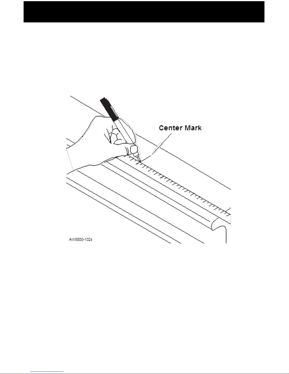
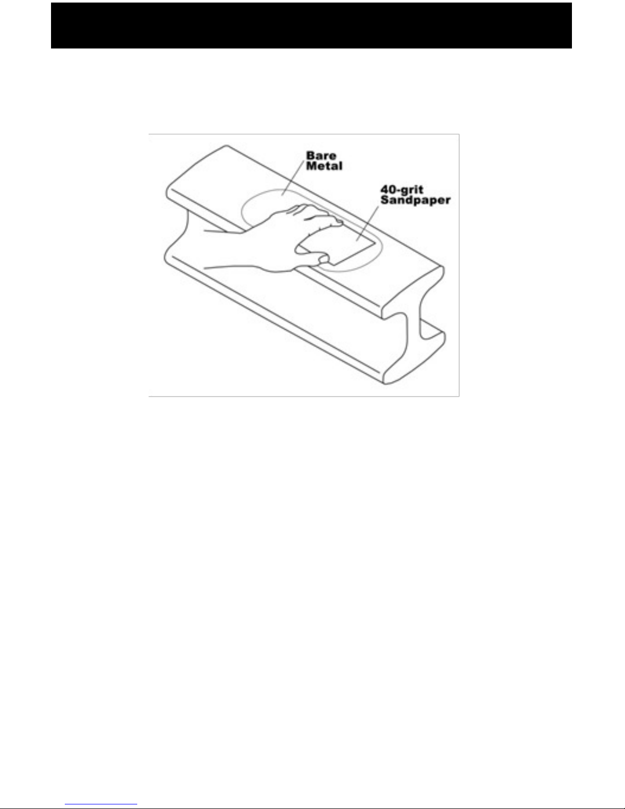
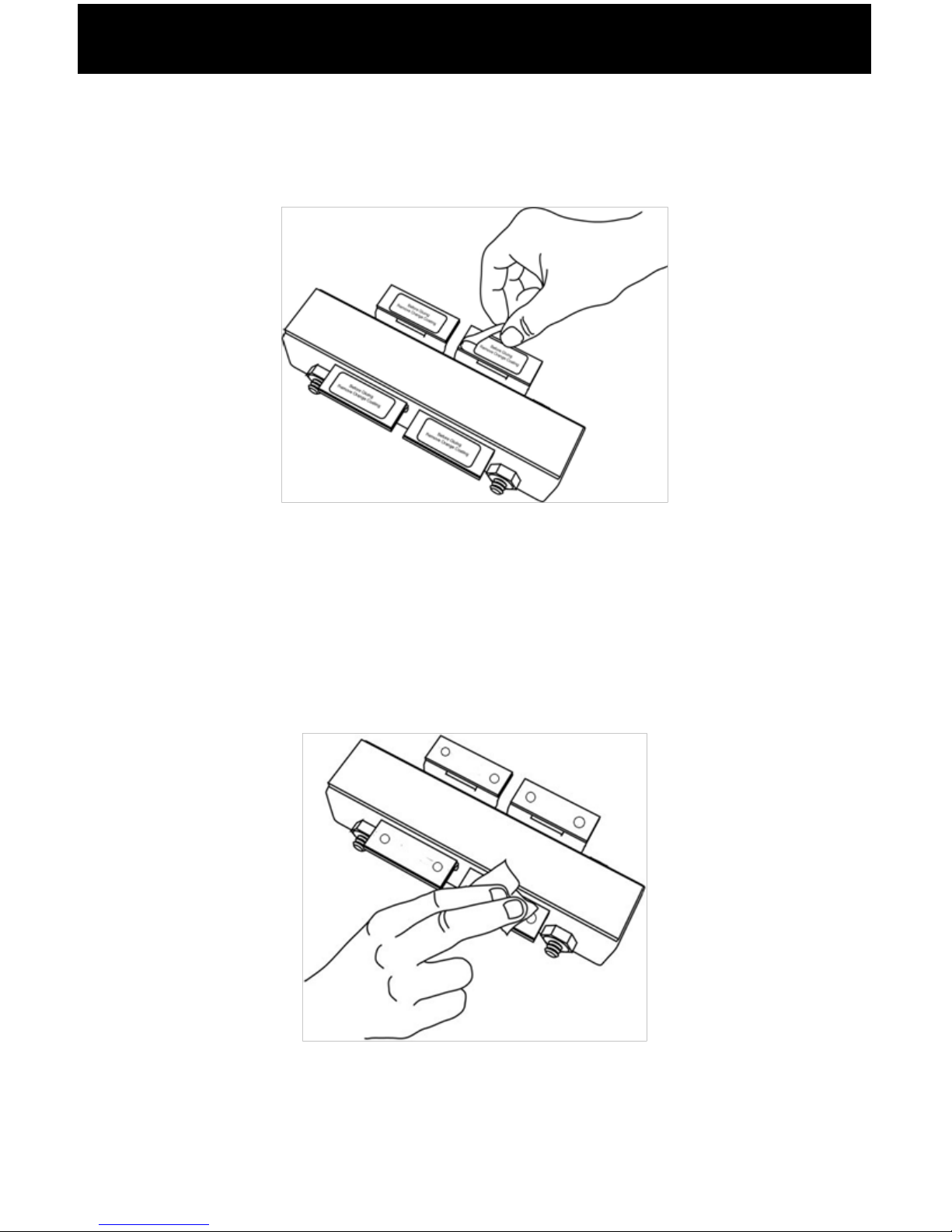
Preparing the Steer Axle Sensor Brackets...............................3
Welding the Bracket......................................................................6
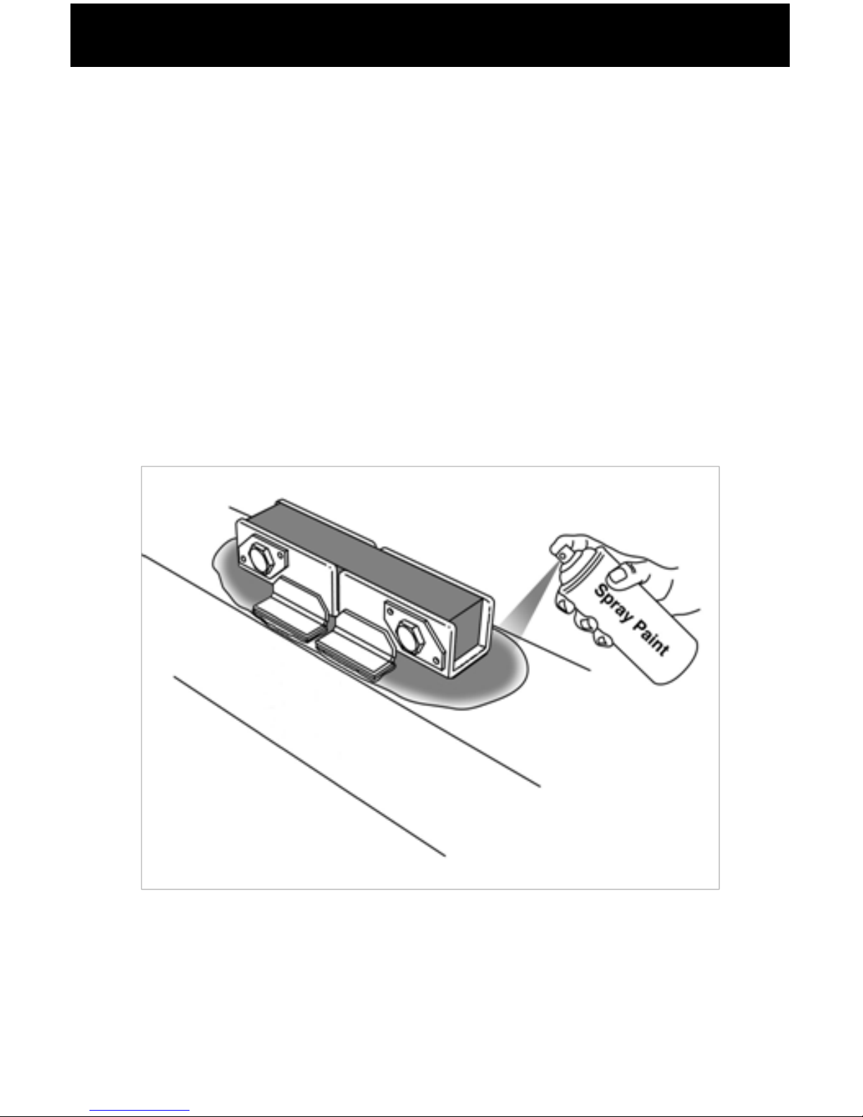
Adding a Protective Spray Paint Coating..................................7
INSTALLING THE DRIVE AXLE SENSOR BRACKET.............................8
Preparing the Camelback Suspension......................................8
Welding the Bracket.....................................................................9
Adding a Protective Spray Paint Coating................................10
ROUTING CABLES..................................................................................11
INSTALLING THE COMLINK AND DISPLAY..........................................12
Preparing the Cab Display for Installation...............................12
Installing the Cab Display...........................................................12
Mounting the ComLink...............................................................13
CONNECTING CABLES...........................................................................14
Power and Ground Table....................................................14
Securing Cables and Reassembling the Dash......................14
INSTALLING AND ADJUSTING THE STEER AXLE SENSOR..............15
INSTALLING AND ADJUSTING THE DRIVE AXLE SENSOR...............17
Setting A/D Values.....................................................................18
Adjusting the A/D Reading.....................................................19
Final Sensor Torque...................................................................20
COVER INSTALLATION..........................................................................21

ii
NOTES......................................................................................................24
LIMITED WARRANTY..............................................................................27
PROCEDURE FOR WARRANTY CLAIMS.............................................28

1
About LoadMaxx for Camelback
Suspensions
LoadMaxx is a weighing system for vehicles that works by using
and converts that number into weight which is displayed in the
truck cab. Weight information, which includes axle group weights
as well as net and gross vehicle weights, are also displayed
The LoadMaxx scale for vehicles with Mack Camelback
suspension includes a dash-mounted display, a ComLink™
mounting hardware for the Camelback suspension.
Please see the Calibration and User Manual, included with your
scale kit, to calibrate your scale after installation.
About Installation
Overview
There are three major components of the LoadMaxx scale that
you will install, listed as follows.
• Electronics: dash-mounted display, ComLink module,
power cables and sensor extension cables
•
•
suspension

2
Tools Required
steer and drive axles.
• Sander/grinder
• 40-grit medium sandpaper
• Chalk or permanent marker
• MIG or ARC welder
• For ARC welder: E7018 welding electrodes OR
• For MIG welder: E70S-3 or E71T-1 welding wire
• Two C clamps
• Flat-blade screwdriver
• Torque wrench, 120 ft-lb
•
• Enamel spray paint, any color
• Tape measure
Optional Tools

3
Installing the Steer Axle Sensor
Bracket
Preparing the Steer Axle Sensor Brackets
1. Locate and mark the center of the steer axle.
2. Using chalk or a permanent marker, mark the top of the steer
this area. If the axle is heavily caked with dirt or grease, use
Brakleen to remove the worst.
3. Using 40-grit medium sandpaper or a pneumatic grinder,
sand the 6” area until nothing remains but bare metal. We
recommend that you partially sand down the mold line as
well.
Marking the Center of the Steer Axle

4
4. Re-mark the center of the steer axle.
and that no axle paint is left under the pad. If there is any
paint at all that will be touching the brackets, sand until it has
been removed.
6. Once you have prepared the axle, place the bracket
rocking in any direction. If the bracket rocks, sand or grind off
NOTE: Make sure that the main body of the bracket does not touch
the axle. Only the feet of the bracket should touch the axle.
Sanding the Steer Axle

5
7. Remove the protective tape from around the bottom of the
bracket assembly.
Removing the Protective Plastic Strips
8. Clean the underside of the bracket assembly with one of the
supplied isopropyl alcohol pads.
Cleaning the Bottom of the Bracket Assembly

6
Welding the Bracket
NOTE: Air-Weigh takes no responsibility for damage or failure of
the steer axle due to improper welding.
1. Place the new bracket assembly at the center of the axle.
Use C clamps to hold the bracket in place. Make sure you
leave the alignment tool in the bracket assembly while
welding.
front and back edges of each bracket piece.
Bracket Assembly Centered on Axle
NOTE: Make sure that the main body of the bracket does not touch
the axle. Only the feet of the bracket should touch the axle.
Do not operate the vehicle while the alignment tool is still in place.
TACK WELD LOCATIONS

7
Adding a Protective Spray Paint Coating
To prevent steer axle corrosion, we recommend you spray paint
around the base of the bracket.
1. Using any enamel-based spray paint, paint around the base
of the bracket and over the welded section. Paint all bare
metal around the bracket completely.
2. Once the paint is dry, we recommend that you paint all
exposed metal a second time.
Spray Paint Coating

8
Installing the Drive Axle Sensor Bracket
Preparing the Camelback Suspension
1. Locate and mark the top center of the trunnion tube.
Sanding the Trunnion Tube
Marking Center of Trunnion Tube
2. Using chalk or permanent marker, mark the top of the
3. Using a grinder or 40-grit medium sandpaper, sand the
marked off area until it is free of paint and other residues.
4. Clean the sanded area.

9
Welding the Bracket
1. Place the mounting bracket assembly on the top center of
the trunnion tube. Mark the center on the alignment tool and
ensure it lines up with the center mark on the trunnion tube.
2. Use C clamps to hold the bracket in place. Make sure you
leave the alignment tool in the bracket assembly while
welding.
Placing the Brackets on the Trunnion Tube
3. Tack weld all 8 corners of the base of the bracket.
4. Fillet weld a full bead on the edges of each bracket piece.
Alignment Tool

10
Adding a Protective Spray Paint Coating
1. To prevent the drive axle brackets from delaminating due to
corrosion, we recommend you spray paint around the base of
the brackets.
2. Using any enamel-based spray paint, paint around the
base of the bracket. Paint all bare metal around the bracket
completely.
3. Once the paint is dry, we recommend that you paint all
exposed metal a second time.
Spray Painting the Bracket

11
Routing Cables
1. Route the 20’ steer extension cable and the 40’ drive
extension cable along their respective axles and the frame,
sensor connections. If at all possible, route along an existing
wire harness. Be careful to avoid routing along pieces of the
frame that may move or cause wiring to rub.
2. Secure the cables loosely to the suspension using zip ties.
NOTE: Keep all cables a minimum of 12” from exhaust piping or
properly shield cables.

12
Installing the ComLink and Display
Preparing the Cab Display for Installation
and its connections. A higher dash position provides better
visibility.
will mount the display.
Installing the Cab Display
the dash.
using 6 in-lbs. of torque. Do not over- tighten the mounting
Display Preperation and Installation

13
Mounting the ComLink
1. Select a location behind the dash for the ComLink module,
ensuring there is adequate access to the scale and the
electrical connections.
2. The ComLink module should be oriented with the connectors
facing downward and installed by either one of the following
methods, using the hardware provided:
Use zip ties through the holes in the ComLink module
mounting ears to secure it to any appropriate wire harness
behind the dash.
-OR -
attached using the 2-sided adhesive tape already in position
on the back of the ComLink module. Remove all dust, grease
pad. Remove one or both of the red strips from the back of
the ComLink module, exposing the adhesive tape. Place
hard enough to ensure adhesion. For best results, push the
ComLink module into place using 15 ft lbs of pressure,
being careful not to crack the case. Using this method will
NOTE: If you are using the optional printer, please see the document
Printer Installation Instructions for information on connecting the
printer to the ComLink.

14
Connecting Cables
The provided cables are used to connect the ComLink to the
vehicle’s electrical system, to the dash display unit, and, if desired,
to an alarm output.
Power and Ground Table
White Wire Vehicle Chassis Ground
Blue/Black Wire with In-
Line Fuse
12VDC or 24VDC Key
Hot Power
Gray Wire/Brown Wire Alarm output 1 and 2
Black Wires Alarm ground Return 1
and 2
1. Connect the white wire to chassis ground.
“hot” side of the 12 VDC or 24 VDC key hot power source.
3. Connect the 10-pin plug of the power interface cable to the
ComLink module.
4. Connect both the 2-pin and the 4-pin plugs of the power
interface cable to the display.
Securing Cables and Reassembling the Dash
1. Connect the extension cable to the ComLink module in the
dash. Drive cables should be connected to Port A and the
steer cable should connect to Port B.
2. Coil and secure any excess wire using zip ties.
3. Tighten all zip ties and trim.
4. Reassemble the dash assembly after all sensors have been
Ensure all connections are tight.

15
Installing and Adjusting the Steer
Axle Sensor
1. Remove the alignment tool from the brackets. Retain the
nuts and bolts.
2. Insert the steer axle sensor with its cable extending toward
the side of the vehicle where the sensor extension cable has
faces up.
3. Align the steer axle sensor with the holes in the steer axle
bracket assembly.
4. Insert one bolt through the bracket hole on the sensor end
with the engraved lettering on it so that the bolthead is
secured in the manufactured bolthead holder. Place a washer
and a nut at the end of the bolt and hand-tighten the nut.
Inserting the Sensor Into the Bracket

16
that the bolthead is secured in the manufactured bolthead
holder.. Hand-tighten the nut.
Attaching the Sensor to the Bracket

17
Installing and Adjusting the Drive
Axle Sensor
1. Remove the alignment tool from the brackets. Retain the
nuts and bolts.
extending toward the side of the vehicle where you’ll route
lettering on the sensor should face up.
4. Slide the bolts through the bracket holes so that the
boltheads are secured in the manufactured bolthead holders.
Inserting the Sensor
Inserting Bolt and Washers into Sensor and Bracket
Other manuals for LOADMAXX
4
Table of contents