Pag. 3 di 88
TABLE OF CONTENTS:
1Company name, address of the manufacturer and introduction 5
1.1 Update of the user’s manual 6
1.2 Warranty 6
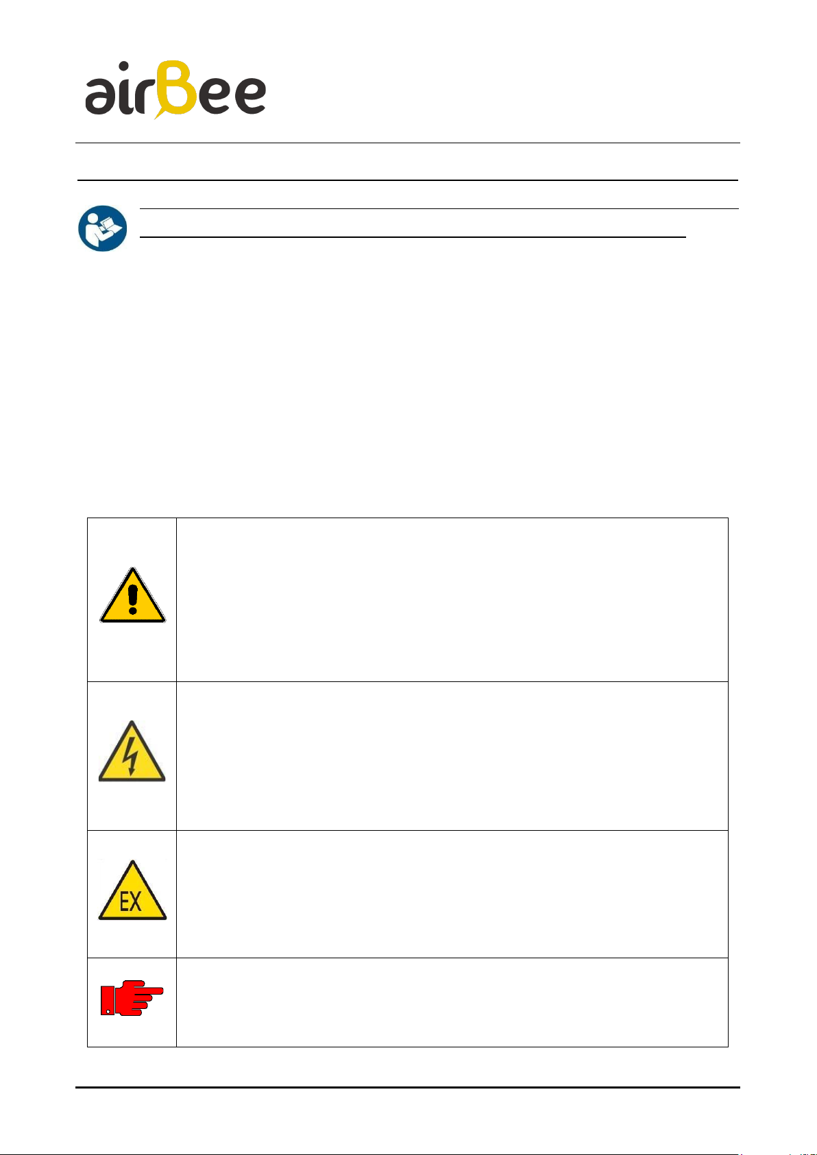
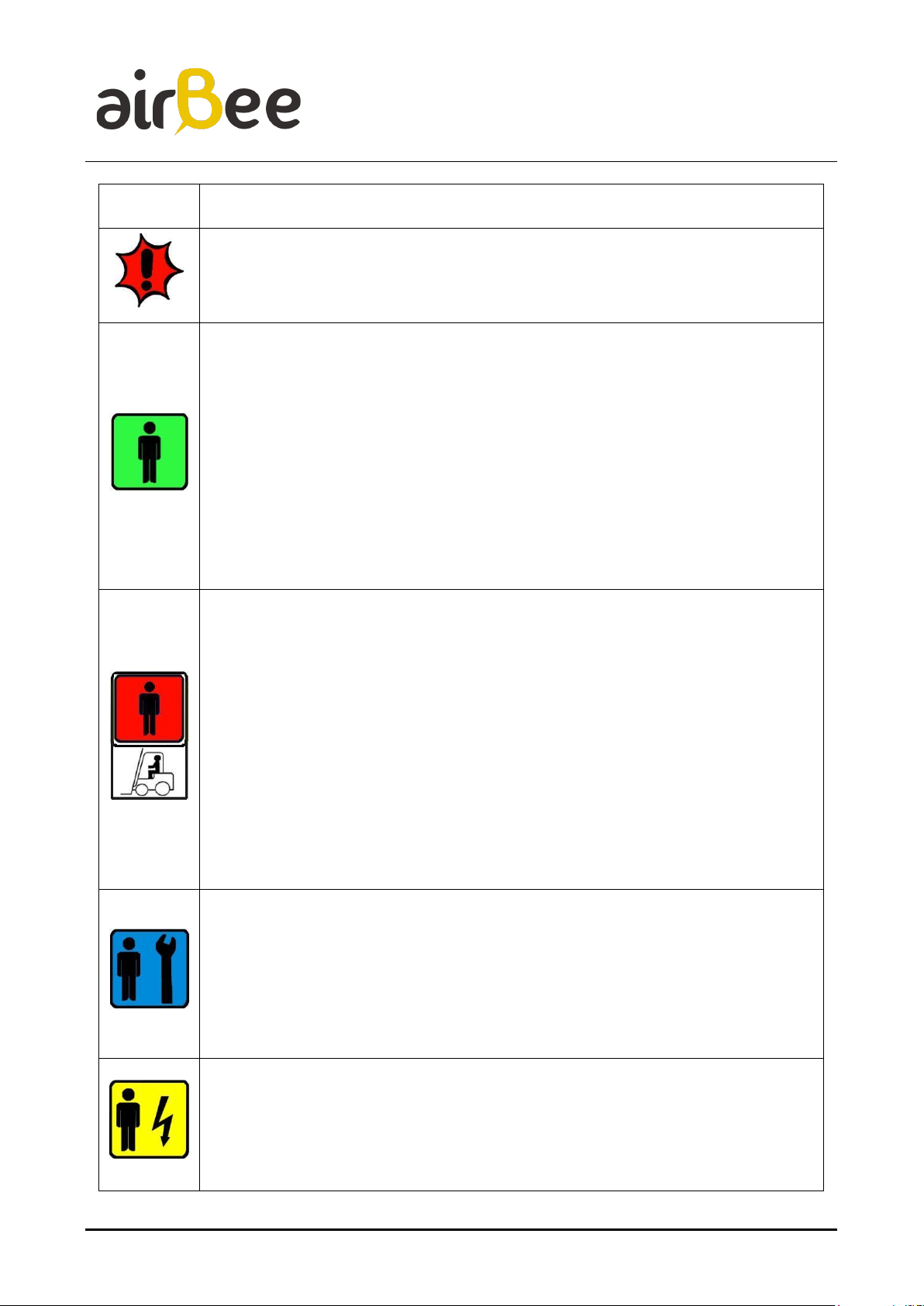
2.1 Summary of symbols and terminology used in this manual 8
Fig.1.1.1 –Symbols 10
Fig.1.3.2 –Examples of PPE symbols (Personal Protective Equipment) 10
2.2 DEFINITIONS 12
2.3 Intended use of the machine 14
Fig.1.5.1 –Air intake into the device 16
Fig.1.5.2 –Air Sanitization Circuit 18
2.4 Education / training of maintenance workers 18
2.5 Reference standard 18
Model 20
Fig.2.2 –Internal filter coated with TiO221
2EC declaration of conformity (Facsimile) 23
3General description of the machine and technical specifications 24
Fig.4.1 –inlet filter H13 24
Fig.4.2 –Scheme of the photocatalysis process 26
3.1 Operation via APP 26
3.2 Manual operation 27
Fig.4.2.1 –Remote Control 28
3.3 Factory Default 28
Fig.4.3.1 –Reset 29
3.4 Detail of visual signaling LED 29
Fig.4.4.1 –Reset signal lights 31
3.5 Scope of use of the machine 31
3.6 Technical Specifications 32
3.7 External application operation 33
3.7.1 SYSTEM INSTALLATION AND ACCESS 33
Fig.4.7.1.1 –Login 35
Fig.4.7.1.2 - Registration 35
Fig.4.7.1.3 –Information 36
Fig.4.7.1.4 –Reading of values obtained from internal sensors 37
3.7.2 New device registration 38
Fig.4.7.2.1 –New device registration 40
Fig.4.7.2.2–Home data 42
Fig.4.7.2.3 –Sensor reading 43
Fig.4.7.2.4 –Description of the MQTT connection 43
4Drawings, diagrams, descriptions and explanations necessary for the use, maintenance and
repair of the machine and to verify its correct functioning 44
Fig.5.1 –Home elevation view 44
Fig.5.2 –Home power supply and motherboard 45
Fig.5.3 –Air flow into the device 46
Fig.5.4 –Initial filtration 47
Fig.5.5 –Base of the device 48