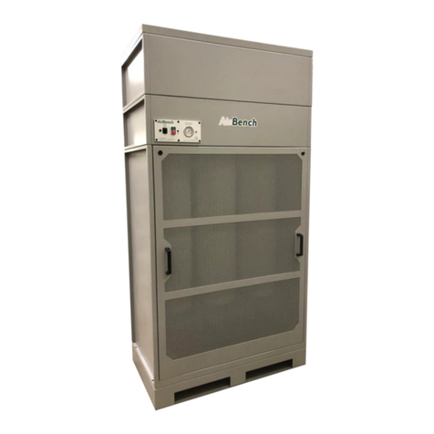
AirBench AOF User manual

© Copyright AirBench Ltd 2022 Page 2 of 20
Cautions 3
Introduction 3
OVERVIEW 4
ABOUT AOF 4
ABOUT THIS DOCUMENT 4
SCHEMATIC AND NUMBERING 5
OPERATION 7
Starting and stopping the system 7
MAINTENANCE 8
Maintenance - Cleaning filters 9
FILTER INDICATION - MECHANICAL GAUGE 12
FILTER INDICATION - LED PANEL 13
AIR PRESSURE SWITCH ADJUSTMENT 14
Troubleshooting 15
Thorough Examination and Testing 17
Technical 18
Warranty Terms 19
AIRBENCH LTD

© Copyright AirBench Ltd 2022 Page 3 of 20
CAUTIONS
Do not place this product near a powerful magnetic field or expose to static
electricity.
Do not drop unit or damage the unit body.
Do not clean with corrosive products.
Pre filter system must be washed periodically. When cleaning pre filter, we
recommend also cleaning the interior of the machine.
This unit is not ATEX rated.
It is your responsibility under ATEX regulations to ensure this unit is located in an
area which is rated as suitable for the specification of the unit.
We do not accept responsibility for any inconvenience or damage caused by
unusual or unspecified applications. If the product is damaged or service is
required, please contact us.
INTRODUCTION

© Copyright AirBench Ltd 2022 Page 4 of 20
Overview
Thank you for choosing AOF as your mist control system. Please read this document before
installation and use.
This document details maintenance activities which are essential to the safe use of your AOF. We
recommend that the Responsible Person reads this manual fully prior to installation and operation of
the AOF.
This document refers to the AOF range. Models of this type are available with a range of filter
configurations. The filter configuration in use is detailed on the system Commissioning Certificate and
on order.
About AOF
AirBench is a dedicated coolant mist / smoke filter system designed for installation to machine tools,
for the removal of contaminants from most types of machining.
AOF is currently patent pending.
About this Document
This document provides general maintenance and operation instructions for the AOF range. It should
be read in conjunction with the Commissioning Certificate supplied on installation. If you have any
concerns or doubts about maintenance or operation of this unit, contact the supplier.

© Copyright AirBench Ltd 2022 Page 5 of 20
SCHEMATIC AND NUMBERING
NO.
Part
AF-10
AF-20
AF-30
1
Flexible hose (std.)
Type
H-150
H-150
H-150
Outside
dia.
Ø150
Ø150
Ø200
2
Flexible hose clamp
(std.)
Type
HB-165
HB-165
HB-215
Outside
dia.
Ø150
Ø150
Ø200
3
Air inlet adaptor with
Jacobs connection (std. x
1)
Type
PM-150
PM-150
PM-200
Outside
dia.
Ø150
Ø150
Ø200
4
Anti-vibration mount
(std.)
Type
AV-832
Machine
Machine

© Copyright AirBench Ltd 2022 Page 6 of 20
5
Oil resistant cable
Type
CA-1.25mm2x4C
Outside
dia.
1.25mm2x4C x3.3M
6
Oil drain hose
(std.)
Type
DH-300
7
Pre-filter system (std.)
Type
PF-250
PF-250
PF-300
8
After-filter
system (std.)
Type
S –Standard (Coolant)
P –Practical (Oil smoke)
9
Telescopic stand
(opt.)
Type
SU-1800
1100-1800mm height

© Copyright AirBench Ltd 2022 Page 7 of 20
OPERATION
Please follow the below information once the system has been successfully installed to ensure correct
use of your mist / smoke filter system
Please ensure this document is fully read and understood prior to operating the filtration system.
Starting and stopping the system
Using the DOL starter supplied as a standard installation is the
means of control of the system.
Use the Green button to start the mist filter unit prior to works
commencing, once the job (or shift) has been completed stop
the system by pressing the red (stop) button.
You do not need to start and stop the system for every part
being machined, ideally start the AOF at the start of your shift
and stop the system when you shut down the CNC machine.
During operation of the unit especially during the first day you
may notice a smell from the unit, this is completely normal.
The final filter (HEPA filter) is stored in an airtight bag prior to
installation, during first operation the system will force air
through the filter which will result in noticing a slight rubbery
smell but this will stop after a few hours of operation.

© Copyright AirBench Ltd 2022 Page 8 of 20
MAINTENANCE
Please follow the points below to ensure your AOF is running as efficiently as possible by carrying out
periodic maintenance on each system.
Maintenance intervals will vary per installation depending on a few factors which are….
●Run hours per week
●Type of CNC (Lathe or Mill)
●Type and amount of Coolant / oil being used
Ideally after an installation is completed and a system is operational, standard procedure would be to
use the system for three months and then open the filter housing to check the state of the pre-filter
and main filter.
This will give a rough indication to the current state of the filters after three months of use. Depending
on the factors listed above you may find very clean or dirty filters.
If the filters visually do not seem blocked or restricted after three months of use it is best to remove
them and clean the filters as described below, filters may appear clean but this is not always the
case.
If the filters are dirty or heavily restricted or showing as amber on the gauge or LED panel please
follow the instructions below in order to clean the filters and improve air flow back to design
conditions, failure to do this will result in a less efficient system and if left long enough could possibly
lead to a fault or damage to the mist filter.
Once maintenance has been completed please ensure you note the date as to when the filters had
been cleaned or replaced and keep this in your maintenance logs.
Remember –maintenance is vital to ensuring an efficient and effective mist filter!
At intervals of at least every 14 months an LEV test (Local Exhaust Ventilation) will need to be carried
out to ensure your mist filter is operating as designed and up to current standards. This is a
requirement under COSHH.
This can be carried out by our fully trained AirBench Engineers - feel free to contact us to get this test
booked in.

© Copyright AirBench Ltd 2022 Page 9 of 20
Cleaning filters
Access
Ensure AOF is switched off and isolated prior to opening
the cover.
To gain access to the pre-filter and main filter you will
need to open the clasp on the front end of the AOF and
open the filter housing.
Depending on installation you may need to remove the
flexible pipe from the unit first by removing the quick
release Jacobs clamp located on the inlet to the AOF.
Once the unit is open you now have access to both
internal filters which will need to be cleaned at least once
every 3 months to ensure system efficiency.
Ensure P.P.E is worn when opening the AOF filter housing
and handling filters.
Pre-Filter
The pre-filter can now be removed by gently pulling on
the foam filter to separate it from the main filter.
To clean –Wash the filter through with a degreaser or
detergent ensuring you remove as much oil/coolant and
swarf as possible from the filter.
These should then be left overnight to allow them to dry
before fitting back into the AOF.

© Copyright AirBench Ltd 2022 Page 10 of 20
Cleaning times will vary per customer so please adjust
your maintenance intervals as required.
Pre-filters should be replaced every 12 months
Main filter
Once the pre-filter has been removed you can now
access and remove the main filter.
These are a very tight fitting as they are an airtight fit
around the inlet of the fan assembly, to remove grasp
the handle and provide a pulling motion until the filter
comes away from the housing.
To clean the main filter please soak in detergent as per
the pre-filter and then using compressed air blow
through the filter from the inside out to remove any
restrictions within the filter, this can then be refitted
along with the pre-filter.

© Copyright AirBench Ltd 2022 Page 11 of 20
Air inlet
When maintaining the filters it is also required to carry
out a clean on the air inlet spigot, these have a mesh
fitted internally (as pictured).
This mesh over time will start to become restrictive and
will require cleaning, the mesh is used to stop any large
pieces of swarf from entering the mist filter and blocking
filters.
While cleaning your pre-filter(s) it is best practice to clean
the mesh with a brush to ensure good airflow into the
mist filter.
Failure to do this will result in the system showing a false
restriction in the pre-filter and will reduce system
efficiency
Final Filter (HEPA)
The final stage filter (HEPA) is not serviceable and should
not be cleaned.
P-Type filter life expectancy 9 -12 months
S-Type filter life expectancy 2 - 3 years (single shift)

© Copyright AirBench Ltd 2022 Page 12 of 20
Filter indication - Mechanical gauge
Normal operation (Green)
If the needle is sat in the green area then this
indicates a system which is running well with no
air flow restrictions or blocked filters
Restricted pre-filter or main filter (Amber)
When the needle is sat showing a low running
pressure this is an indication that your pre-filter
or main filter is becoming restricted or has
become blocked.
An amber indication requires attention to the air
inlet mesh, pre-filter and main filter to be
cleaned as described above

© Copyright AirBench Ltd 2022 Page 13 of 20
Restricted final filter (HEPA) (Red)
When the needle starts to show a high pressure
above the green area this is stating that your
final filter is either restricted or blocked and will
require replacing as soon as possible
Filter indication - LED panel
Normal operation (Green)
If the LED indication panel is showing green then
this indicates a system which is running well
with no air flow restrictions or blocked filters

© Copyright AirBench Ltd 2022 Page 14 of 20
Restricted pre-filter or main filter (Amber)
When the LED panel is showing as amber this is
an indication that your pre-filter or main filter is
becoming restricted or has become blocked.
An amber indication requires attention to the air
inlet mesh, pre-filter and main filter to be
cleaned as described above
Restricted final filter (HEPA) (Red)
When the LED panel is showing red this
indicates that your final filter (HEPA) is either
restricted or blocked and will require replacing
as soon as possible.
Air pressure switch adjustment
If after installation your mist filter system requires relocating to another CNC machine this is easily
done but should be carried out by a trained and competent person.
Once the mist filter has been relocated it will be necessary to run through the commissioning process
to address the air pressure switches as these may need to be altered to allow for correct air
measurements to be taken, this is vital to ensure that LED panel trigger points have been set
correctly.
If the pressure switches are not re-commissioned the system will not react accordingly to pressure
change across the filters and will not indicate current and correct filter indication. Instruction to
correctly alter the pressure switch settings can be found within the AOF installation manual

© Copyright AirBench Ltd 2022 Page 15 of 20
TROUBLESHOOTING
The following instructions are intended for qualified service personnel only.
Disconnect power before servicing the unit.
The motor is operating, but no air is drawn into the unit.
Reason
Solution
The fan is rotating in wrong direction.
(The fan must be rotating clockwise)
Turn off the power. Swap each 2 of the R/S/T cables in the
main power supply unit. Turn on the power again and make
sure the fan is rotating clockwise.
The motor does not start after switching the power on.
Reason
Solution
A. Incorrect power voltage is supplied.
B. Power switch is faulty.
A. Check whether the supplied power voltage is correct.
B. Please contact us to replace the power switch
Machine is making a loud noise.
Reason
Solution
A. The air inlet is jammed
B. The air hose is deformed or
squashed
A. Check and clean the shielding net of the inlet.
B. Check the position of the air hose to make sure the
air is flowing smoothly.

© Copyright AirBench Ltd 2022 Page 16 of 20
Machine is vibrating during operation.
Reason
Solution
A. Improper installation area.
B. The oil mist collector is positioned
without anti-vibration screws
A. The oil mist collector must be installed on a proper
area that is stable and vibration resistant.
B. Anti-vibration screws are necessary for positioning
the oil mist collector (It is a standard accessory in the
package).

© Copyright AirBench Ltd 2022 Page 17 of 20
THOROUGH EXAMINATION AND TESTING
If AOF is used as an LEV system it must be tested at regular (normally 12 month) intervals and
certificated under the COSHH regulations. This service is available from us, or our approved testers.
Thorough examination and test should include:
-Ensuring the prescribed maintenance routines are being completed and recorded within the
system logbook.
-Condition check of fan, filters, electrics.
-Performance testing according to recommended duct velocities.
-Visual check that operators are working within effective area.
-Visual check of effectiveness using, for example, smoke tubes.
Completion of Thorough Examination and Testing should be recorded within the system logbook.

© Copyright AirBench Ltd 2022 Page 18 of 20
TECHNICAL
Model
Power
Source
Motor
Air Flow
Rate
(m3/min)
(50Hz/60Hz)
Static
Pressure (kPa)
(50Hz/60Hz)
Noise Value
db(A)
(50Hz/60Hz)
Filtering
Effect
Weight
(kg)
Air
Inlet
Port
Effective
Filtration
AF-10P
3Ø
AC220V
or
AC380V
0.2 KW
11/14
0.78/1.15
60/63
99.97%
EU
E12
Standard
39
Ø150
<4m3
AF-20P
0.4 KW
19/22
1.71/2.06
66/71
42
Ø150
<12m3
AF-30P
1.15 KW
37/42
1.92/2.35
68/73
66
Ø200
<24m3
Above table is showing the testing results from the P series models.
Model
A
B
C
D
D1
E
F
G
H
I
J
K
L
AF-10P
613
379
726
231
148
300
335
283
25
25
426
355
313
AF-20P
653
379
736
231
148
320
350
298
25
25
426
355
313
AF-30P
765
432
808
290
200
388
420
368
25
25
492
408
313

© Copyright AirBench Ltd 2022 Page 19 of 20
WARRANTY TERMS
1. During the warranty period, we will provide free repair or part replacement for mechanical or
electrical issues arising as a result of manufacturing defects.
2. The warranty period is one year following date of supply (or date of installation if installed by us
or our approved installers)
3. During the warranty period, if any of the following conditions occur, we will charge for the
maintenance cost:
3.1 Improper operation or use in a special working environment (For example:
high temperature or aggressive chemical environments)
3.2 Self-repair or self-modification, breakage or transportation damage.
3.3 Problems caused by abnormal power supply or incorrect voltage or frequency.
3.4 Use in a location containing too much dust or oily dust without proper maintenance.
3.5 Lack of routine maintenance or use of non-approved parts.
4. If any of the following conditions occur, we will charge the actual costs:
4.1 The warranty period is over.
4.2 The warranty is not shown.
4.3 The contents of warranty (such as model and serial number) do not comply with the actual
product.
4.4 Problem is caused by external damage, natural disaster or other root causes outside the
manufacturers control.
5. Consumable items are excluded from warranty; consumable items include filters and external
cabling.
6. When installing the oil mist collector, if service space and personnel safety are not considered,
service and repair may require additional works. The user shall be responsible for the cost of
these additional works.
7. If the replacement part is not available after five years from the date of purchase, we will
endeavour to provide the equivalent for repair. However, in some cases, we are sorry for not
being able to provide an equivalent for replacement.
8. The warranty is effective only for the original purchaser. If the product is resold other than by an
authorized distributor, the warranty will be terminated.

© Copyright AirBench Ltd 2022 Page 20 of 20
Other manuals for AOF
1
Table of contents
Other AirBench Water Filtration System manuals
Popular Water Filtration System manuals by other brands

Mart
Mart EQ-1 manual

Nederman
Nederman FilterCart W3 instruction manual

US Water Systems
US Water Systems Aquapurion 5 Installation and maintenance manual

Frequency Devices
Frequency Devices CPCI32FF user manual

Yamato
Yamato Autostill WG251/1001 instruction manual

Honeywell
Honeywell HRO-50 Product installation & operation manual

Finerfilters
Finerfilters RO-H-50G Installation and maintenance manual

Whirlpool
Whirlpool WHKF-IMTO Installation, use & care guide

Allfyll
Allfyll Series N instruction manual

Vixen Air
Vixen Air VXF3938B installation guide

AquaScape
AquaScape 95110 installation instructions

PREMIER TECH
PREMIER TECH Ecoflo STB-500B owner's manual