AirCom AST30 User manual

AIRCOM®- 2022 - v. 1.0
AVAILABLE MODELS
mod. AST40
Airless pump with flow rate of
6.5 l/min

EN
Index
.04
.05
.06
.07
.08
.09
.11
.12
.13
.14
.15
.16
.17
.24
.10
.18
Packing
Description
Technical features
Products and dimensions
Usage
Pipes connection
Safety
Painting cycle
Pressure discharge
Maintenance
Cleaning
Filter and gasket replacement
Anomaly resolution
Scheduled maintenance
Spare parts and components
Disposal and Support
Instruction manual
WARNINGS!
Carefully read and follow all instructions and safety precautions
before using the product.
MANUALS
Our manuals are available at aircom.it/en/support/manuals/
Or, by scanning the QR Code on this page.

aircom.it .04
OBBLIGO DI
IMPIEGO DI
OCCHIALI E
MASCHERINA
PACKING
The pump is packed in a cardboard box. All components supplied as
standard are placed in the same package.
The weight of the equipment plus the packaging is ~27 Kg.
STORAGE
During transport and storage, make sure that temperatures between -15°C
and 40°C or 50°C for short periods not exceeding 24 hours are not
exceeded, which could damage the unit itself.
If the unit is to be stored, make sure it is stored in places with humidity
between 30% and 80%.
PLATE DATA
On the front plate, the equipment bears the manufacturer's identification
plate and the 2006/42/CE STANDARDS compliance plate, also represented
below.
The plate must not, under any circumstances, be removed, even if the
equipment is resold. For any communication with the manufacturer, always
quote the serial number (shown on the plate itself). On the body of the
pump there are some pictograms indicating safety warnings which must be
carefully observed by anyone preparing to use the painting unit. Failure to
comply with the provisions relieves the manufacturer from any damage or
injury to people or things that could derive from it and makes the operator
himself solely responsible towards the competent bodies. Replace the
nameplate and any removed, damaged or illegible stickers.
EN

aircom.it .05
The equipment covered in this manual is a painting unit which allows you to
spray paint any type of material. Characterized by considerable practicality,
versatility and ease of use, the AST30 employs a pneumatically operated
high-capacity piston pump unit.
The airless spray system allows to considerably reduce the paint mist and
to guarantee a great transfer efficiency (over 80%). The system also makes
it possible to obtain perfect micro-atomization with considerable savings in
paint and a better surface finish.
The modularity of the equipment allows you to purchase only the pump unit
and then customize it with a considerable number of accessories (AIRLESS
GUN, PUMP HOLDER TROLLEY, GRAVITY TANK, SELF-CLEANER, etc.)
DESCRIPTION
EN

TECHNICAL FEATURES
aircom.it .06
The painting unit uses a pneumatic system that can be fed at a pressure
between 6 and 8 bar. Compressed air is used to obtain the movement of
the paint pumping piston and to obtain a high spraying pressure with any
type of paint and to obtain a high spraying pressure with any type of
paint without the use of air. All gaskets are of a special type with high
quality and high resistance; the valves are in stainless steel, the seats
are in hard metal.
FEATURE AST30
CAPACITY
PRESSURE RATIO
OPERATING PRESSURE
NOMINAL PRESSURE
DROP TANK
PREVALENCE
AIR OUTLET FITTING
PAINT INLET FITTING
NOZZLE
WEIGHT
SOUND PRESSURE LEVEL
PEAK VALUE
6.5Lt/min.
30:1
240 bar
8 bar
5 Lt.
50 metres
¼”M
F 3/4” 90°
0,007 – 0.026
30 kg.
Laeq=75 dB (A)
99,7 dB
EN

aircom.it .07
The AST30 painting units are designed for painting large surfaces and for
uses such as: painting on behalf of third parties, shipyards, large and
medium-sized carpentry shops, industrial body shops, mechanical
constructions in general. The products that can be supplied are: high solid
paints, normal paints, primers and glues. For the use of the equipment with
particular products, the approval of the manufacturer must be obtained, and
the adaptation of the technical characteristics of the unit for the processing
of such products.
Solvents such as trichloromethane and chloromethylene (dichloromethane)
can chemically react with the aluminum which makes up most of the pump,
leading to dangerous explosions. We advise you to always read the technical
data sheet of the product you intend to apply very carefully, avoiding the
use of materials that contain this type of solvent. Do not use regenerated
solvents (cleaning thinners), make sure they are free from acids (caused by
regeneration); these acids are responsible for the corrosion of the pistol.
PRODUCTS AND DIMENSIONS
EN

aircom.it
Before using the paint pump, check that it has not suffered damage due
to transport or storage conditions.
Also check that all the optionals ordered and all the components supplied
as standard are contained in the packaging.
Always wear the prescribed PPE; gloves, mask, goggles, in compliance
with workplace safety regulations. As a first step, it is necessary to make
sure that the lines are able to correctly feed the pump, in compliance
with the safety standards.
The unit is supplied with a condensate filter with regulator, it is
recommended to feed with a pressure of 8 bar Max.
It is recommended to use dry compressed air for best painting results.
.08
USAGE
EN

aircom.it
The unit is supplied disassembled. To assemble the pipes, proceed as
follows (using the following drawing):
• Screw the pipe with the suction filter (E) or the 5 Lt tank to the
attachment (1) of the unit.
• Screw the paint return pipe (F) to the connection (2) of the unit.
• Connect the compressed air network to the inlet (M) of the pressure
regulator (L).
• Connect the paint hose of the gun (B) to the fitting (3) of the unit.
• Connect the ground.
.09
PIPES CONNECTION
1
L
2
3
E
F
B
M
• Check the connections before activating the system.
• Do not kink tubing near fittings, and do not use damaged or worn
tubing.
• Do not try to repair any leaks.
• Pay close attention to the writing on the pipes.
• Do not exceed the maximum pressure indicated by the
manufacturer.
• Given the high power of the pump (up to 240bar), we recommend
the use of certified and tested guns up to 300 bar.
EN

aircom.it .10
The painting MUST preferably take place in a special painting booth
equipped with a suction hood. Do not use the unit if the vacuum system
is not running. Wear protective gloves, goggles and a mask with filters
for breathing with activated carbon and clothing suitable for body
protection.
The pneumatic piston pump must only be used by competent and trained
personnel for its safe and correct use. Make sure that the personnel
assigned to use it have received adequate training and have fully
understood this user manual. To use the spray gun, COMPLY STRICTLY
with the prescriptions and safety criteria indicated below.
• Always work on the equipment protected by the prescribed PPE; gloves,
protective masks, breathing filters with activated carbon, clothing suitable
for body protection.
• The pump is used with paint products or solvents, bear in mind that
these are highly flammable, therefore use the system in well-ventilated
environments and avoid any action that could cause fires (example:
smoking, high temperature slag or shavings, sparks or any electrical
risk).
• CHECK the chemical compatibility of the products to be used from their
safety data sheets.
• The use of products containing organic solvents can cause poisoning
due to the emission of toxic vapours.
• DO NOT USE with food or medicines.
• DO NOT EXCEED the maximum operating pressures indicated (see
paragraph 2.3). BEFORE any disassembly, cleaning, maintenance and
reassembly operation RELEASE the pressure in the pipes
• Never point the paint gun at the human body or at animals.
• Do not modify or alter the equipment as supplied; in addition to being
able to cause malfunctions, or worse, even dangerous failures, you would
invalidate the guarantee.
SAFETY
EN

aircom.it .11
PAINTING CYCLE
• Half fill the lower cup with synthetic machine oil.
• Prepare the paint following the manufacturer's instructions.
• Immerse only the float (or fill the 5 L gravity tank) with the prepared
paint and open the return cock.
• Any hoses used for suction from drums or various containers must be
cut obliquely at their ends to prevent them from sticking to the bottom
and must be of the type reinforced with a rigid spiral.
• Open the inlet air cock and adjust the air pressure to the desired
value, then activate the gun trigger.
• Begin painting operations.
END OF THE WORK SESSION
• Close the inlet air valve.
• Extract the floater.
• Close the paint return cock very slowly.
• Discharge the product contained in the pipes by pressing the gun
lever.
• Thoroughly clean the unit.
NEVER OPEN the return valve before having turned the pressure
adjustment handwheel to minimum.
EN

aircom.it .12
EN
PRESSURE DISCHARGE
When the supply air is removed, residual pressure remains in the product
passage pipes which can cause serious injury. First, release the residual
pressure:
• Remove air from the system.
• Screw the needle stroke regulating handwheel on the spray gun almost
completely.
• Close the atomizing air of the gun.
• Pull the control lever of the gun, directing the jet into the paint
container.
• Open the pump return cock.
• Without disconnecting the spray gun from the pump, clean the system:
• Lift the suction system out of the paint container and let it drain well. If
using the gravity tank, remove the return tube and place it in the paint
container.
• Regulate the supply air to the system at 1 bar and empty the paint from
the pump.
• Immerse the suction system in the solvent (or fill the gravity tank). Let
the solvent circulate inside the pump body for a few minutes.
• Close the return cock. The solvent arrives at the airbrush.
• Close the paint supply tap, pull the lever and discharge the paint into the
product can. Release the lever when the solvent appears.
• Pull the control lever discharging the solvent into the appropriate can,
through the airbrush for a few minutes. Open the return cock and close
the general supply air.
EMERGENCY SITUATIONS
FIRE: Use powder extinguishers, which must be located near the
equipment as required by LAW (Legislative Decree 81/08 safety in the
company) DO NOT USE WATER. Personnel must be trained to know how
to operate under such conditions.

aircom.it .13
MAINTENANCE
Adequate maintenance is a determining factor for a longer life of the
equipment in optimal operating conditions and performance, and ensures
functional safety over time. It is recommended to have the maintenance
operations carried out by trained personnel. Personnel must be provided
with personal protective equipment commonly used for similar operations,
and follow the safety procedures prescribed in the following chapter.
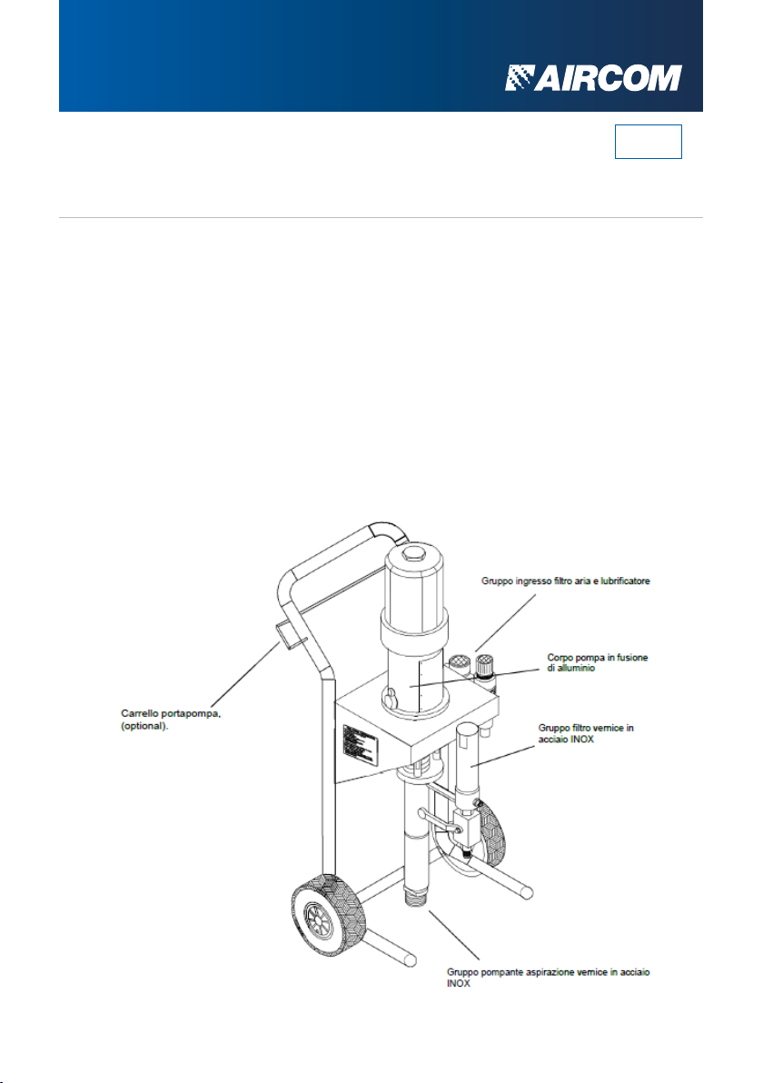
Routine maintenance of the AST30 system is very simple and does not
require particular interventions as the mechanical components of the
system are lubrication-free. During operation, the friction of the stem on
the seals can cause product leakage into the cup (when the system is new
this occurs after about 30/40 hours of operation). These leaks are minor at
the origin, but, if neglected, they can irreparably damage the pumping
element. The leak is due to settling of the gasket pack. It is important to
intervene immediately by adjusting the gasket pack with the special key
supplied with the system.
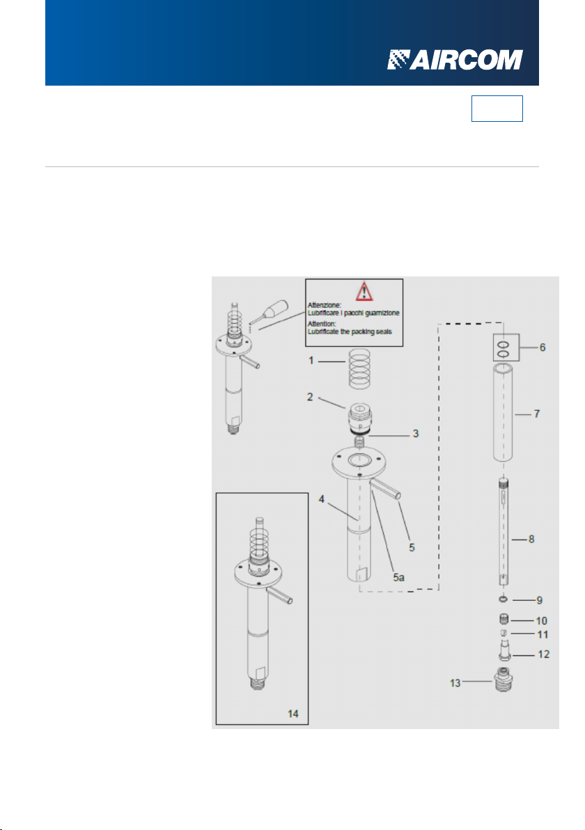
REGISTRATION OF THE GASKETS PACK
The seal pack adjustment must be carried out with the pumping rod in
motion, and in the absence of product. Open the recirculation tap, adjust
the supply air to 2 bar (the stem begins to move), with the special spanner
provided, rotate the cup clockwise. For minor leaks, it is sufficient to give a
small amount of pre-charge to the seal pack (AVOID BLOCKING THE ROD
WITH AN EXCESSIVE ROTATION OF THE CUP).
• Disconnect the air supply before removing any part of the unit or making
any replacement of components.
• Do not wear rings, watches, chains, bracelets, etc. during maintenance
operations.
• Always use personal protective equipment (gloves, goggles, safety
shoes).
• Use only original spare parts.
• Do not use open flames, sharp points or pins for cleaning.
• No smoking.
EN

aircom.it .14
CLEANING
The external surfaces of the unit must be cleaned at the end of each
working day or in any case at the end of each work. This allows you to
keep the unit in good condition. For external cleaning, the use of a soft
cloth soaked in thinner or a detergent solution is sufficient.
To ensure flawless operation of the equipment over time, the paint circuit
must be cleaned daily or in any case at the end of each job to prevent
product residues from drying inside the equipment. Cleaning must be
extended to the entire system, gun and hoses included. The entire
cleaning takes place without disassembling its components.
1. Lift the suction and recirculation pipes out of the product canister,
making them
2. to drain.
Carry out the pressure relief procedure.
3. Immerse the tubes in a can containing clean solvent and let the
solvent circulate inside the pump for a few minutes, opening the supply
air (regulated at 2 bar) and the recirculation valve.
4. Close the circulation valve.
5. Release the lever safety catch and discharge the paint residues left in
the gun high pressure hose into the solvent can
(continue the operation until clean solvent appears).
6. Close the air supply, carefully open the recirculation valve and
discharge the cleaning solvent into the can. The recirculation cock must
remain open until the system is used again.
7. Clean the line filter by disassembling and washing it, paying particular
attention to the filter sieve and the gun.
8. Carefully clean the inside of the product passage gun head.
EN

aircom.it .15
FILTER REPLACEMENT
After about 100 hours of operation it is
necessary to clean or replace the
return paint filter. The life of the filter
depends exclusively on the type of
paint used. To replace it, unscrew the
cylinder (1) then remove the filter (2)
(see figure). Replace or clean the filter
then reassemble everything.
Before opening the "tube" containing
the filter, release the pressure it
contains by opening the recirculation
cock.
Cover cylinder
Return tap
GASKETS
After about 30/40 hours of operation (with new equipment) it is necessary
to check for leaks from the stem gasket (the leak is due to the settling of
the seal pack).
The adjustment must be carried out with the special key supplied and with
the pumping stem moving in the absence of product. Then open the paint
recirculation cock, bring the supply pressure to 2 bar (check that the stem
starts to move), then turn the gasket holder cup clockwise. For slight leaks
(usually after 50/80 hours of work) a slight pressure on the gasket holder
cup is sufficient. Be very careful not to block the stem.
EN
Filter

aircom.it .16
EN
ANOMALY RESOLUTION
PROBLEMS POSSIBLE CAUSES SOLUTIONS
The pump doesn’t work No pressure inside
Check that there is pressure
in the supply air circuit, open
the air ball valve and the
pump pressure regulator.
• Press alternately the starter
buttons located on the sides
of the exchanger.
The pump running very well but
there is no paint to the spray
gun
No pressure in the
pump
• Check that there is pressure
in the supply air circuit, open
the air ball valve and the
pump pressure regulator.
• Check that the suction pipe
or the suction valves are not
blocked by hardened paint
residues.
The paint flow is insufficient
and does not vary by increasing
the supply pressure.
• Check that the suction
filter is not partially blocked.
• The paint has too high
viscosity.
• Spray gun nozzle hole
blocked by dry paint.
• Clean tube and filter.
• Dilute the paint according
to the manufacturer's
instructions.
• Clean tube and filter.
• Clean the nozzle needle
and cap without using
metal objects.

aircom.it .17
EN
SCHEDULED
MAINTENANCE
After about 100 hours of operation, it is necessary to clean or, if necessary,
replace the steel filtering element (sieve) of the filter. The efficiency of the
filter cartridge depends exclusively on the type of paint used. To replace it,
unscrew the cylinder (1) then remove the filter element (2), see figure
below.
Replace or clean the filter element, then reassemble everything.
Before opening the filter unit, release the pressure it contains by opening
the recirculation cock.
OPERATIONS FREQUENCE CONDITIONS
Daily
Weekly
Monthly*
Half yearly *
Cleaning the complete unit
X
Operations to be performed with the
equipment stationary without carrying out
work activities
Check the hoses integrity
X
Check the ball valve working
X
Check the presence condensation
X
Check the clogging of the paint
X
Operations to be performed with the
equipment stationary without carrying
out work activities
filter
Check the clogging of the air filter
X
Check if the screws are fixed very well
X
Check pneumatic connection’s
X
Check pump membrane wear
X
Check pump shaft wear
X
(*) Operation to be performed just from trained and professional operators

aircom.it
SPARE PARTS
COMPONENTS LIST
ENGINE
Bell closure cap
O-ring seal
Engine bell
Guide rod
O-ring seal
Air motor exchange kit
Air closure rubber kit
Control plate
Exchanger block
Engine piston
Piston rod
Motor stem guide bushing
Rubber sealing ring
Seeger ring
O-ring seal
O-ring seal
Body Pump
Post data plate
Front logo plate
Noise panel
Swivel fitting diam12 M3/8”
Complete air motor
1
2
3
4
5
6
6a
7
8
9
10
11
12
13
14
15
16
17
18
19
20
21
EN

aircom.it
COMPONENTS LIST
PUMP GROUP
1
2
3
4
5
5a
6
7
8
9
10
11
12
13
14
EN
SPARE PARTS
Pumping protection spring
Closing cup holder
Upper gasket pack kit
Stainless steel pumping body
Stainless steel filter extension
Kit of 10 copper gaskets 3/8” G
Copper washer + Gasket
teflon
Shirt
Stainless steel pump stem
Washer
Lower gasket pack kit
Kit of 3 balls 5/16”
Stem valve
Complete suction valve
Stainless steel color pumping kit
Table of contents
Other AirCom Water Pump manuals
Popular Water Pump manuals by other brands

Parkside
Parkside PBZS 5 A1 Original instructions

Trillium
Trillium 10-WSP Installation, operation & maintenance instructions

Mira
Mira Enhance Installation & user guide

Edwards
Edwards Cryo-Cooled Diffstak CR63/150 instruction manual

OSNA
OSNA GH Original operating manual

Wilden
Wilden H220 ENGINEERING OPERATION & MAINTENANCE MANUAL