SMITH & LOVELESS Sonic Start Streamline Installation instructions

1
SONIC START®STREAMLINETM FOR PISTA®
RETROFIT KIT - 1 PUMP
Reorder #H67A253
Installation & Operation
Instructions
Smith & Loveless Inc.
Thank you for purchasing the Smith & Loveless, Inc. patent-pending
SONIC START®STREAMLINETM for PISTA®Retrot Kit, S&L Part
No. H67A253. This Kit has all of the parts required to convert your Top
Mounted PISTA® Turbo Grit Pump from electrode to the SONIC START®
STREAMLINETM Vacuum Priming System.
®
Part #: 67P2
PN: H67A253

2
As you read this manual, please take extra notice of the bodily injury warnings
called out with the internationally known symbol seen here. We have inserted
these warnings to help ensure operator safety. Following the bodily injury
warning, one of the following three words will appear:
DANGER: Indicates an imminently hazardous situation which, if not avoid-
ed, will result in death or serious injury. These signs appear with a red back-
ground and white letters.
WARNING: Indicates a potentially hazardous situation which, if not avoided,
could result in death or serious injury. These signs appear with an orange
background and black letters.
CAUTION: Indicates a potentially hazardous situation which if not avoided
may result in minor or moderate injury. These signs appear with a yellow
background and black letters
OPERATOR SAFETY
TABLE OF CONTENTS
Topic Page
Operator Safety 2
Parts Included In Kit 3
Tools Required 4
Installation Steps 5
Operating Guide 27
Troubleshooting Guide 29
Recommended Replacement Parts 31
Warranty 31
Keep these instructions with your equipment Operation & Maintenance Manual
once this kit is installed. This document also serves as the operation instructions
for the SONIC START® Probe.
!
!
!
!
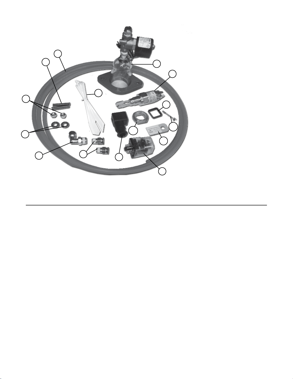
3
Item Quantity P/N Description
1 1 4L628F SONIC START®Prime Sensor Probe
1A 1 SONIC START®Fitting Ring
1B 1 SONIC START®Magnet Testing Unit
1C 1 SONIC START®Electrical Fitting
1D 1 SONIC START®Screw
1E 1 SONIC START® Square Gasket
2 1 4L264S SONIC START® Operating Module
3 1 87B728A Dome & Solenoid Valve Assembly
4 2 6L200DH Stainless Steel Studs
5 2 6L65F Washers
6 2 6L30K Nuts
7 1 1L546D Elbow Tubing Connector
8 2 1L460D Male Tubing Connector
9 15 ft. 1L142BC Tubing
10 6 5L150A Cable Ties
11 1 67P2 Installation Instructions (This Document), not shown
PARTS INCLUDED IN KIT
Please make sure your kit
contains all of the parts and
quantities noted in the Item
and Description section
below, and assure that none
of the parts are damaged
before starting to install this
kit. Report any damaged or
missing parts to the Smith &
LovelessPartsDepartmentat
(800) 922-9048.
8
5
1D
1B
1
1C
1A
Your kit contains the following parts:
7
4
61E
2
3
10
9

4
TOOLS REQUIRED
The following list of tools is required to com-
plete this installation:
• Phillips Screwdriver
• Standard Screwdriver
• Adjustable Wrench or Set of Open End
Wrenches
• Socket Wrench and Extension, 3/8” drive
• ½” Socket
• 3/4” socket
• Wire, 14 gauge, red, green and white
• Wire cutters
• Wire strippers
• Wire crimpers
• Wire nuts
• 1/2” Conduit ttings
• 1/2” Flexible or rigid conduit
• 1/2” Conduit Body
• Control Panel Schematic
• Teontape
• Plumbers’ Grease, Petroleum Jelly or
non pumice hand soap
• Drill and Tap Kit (S&L part number
H87A390A) or Tools to Tap a ½”
NPT Hole
• Drill – ½” drive
• 3/4” Drill Bit or Knockout (to put a
3/4” hole in the control panel)
• #20 Drill Bit
• Hammer
• Punch
• Torque Wrench
• Knife
CAUTION: Use proper personal safety equipment when installing this kit. Eye
protection, non-skid safety shoes, hard-hat, hearing protection and gloves must be
used for the appropriate condition. Failure to do so could result in bodily injury.
!
This kit is designed for use on Top Mounted
PISTA®Turbo Grit Pumps that do not require
explosion proof components. If explosion
proof components are required, use kit
PN: H67A254. For a heated and insulated
cover down to -300F for the dome and solenoid
valve assembly, order the STREAMLINE™
Jacket kit PN: H67A262.
Before starting, check the existing vacuum
dome assembly on the Top Mounted PISTA®
Turbo Grit Pump. Does the dome have one
or two holes in the top of the plastic dome?
If it has one hole, you have everything you
need. If the dome has two holes, then you will
also need to order one (1) PN: 11L47D Quad
Ring and one (1) PN: 87A225 Retrot Adapter
Ring before installing this kit. Parts can be
ordered from the Smith & Loveless, Inc. Parts
Department at (800) 922-9048.
INSTALLATION NOTE: Additional ttings
and exible or rigid conduit are required to
complete the installation of this kit. The SONIC
START® Probe and Solenoid Valve come with
½” conduit threaded ttings. Enough conduit
of the desired type (rigid or exible) will be
required to run from the SONIC START® Probe
to the panel with the electrode relay and from
the solenoid valve that will be mounted on top
of the vacuum dome to the vacuum priming
panel where the vacuum pumps are located.
All Wiring and conduit must meet the National
Electric Code requirement for classication,
division, and/or zone where applicable.
BEFORE YOU START
5
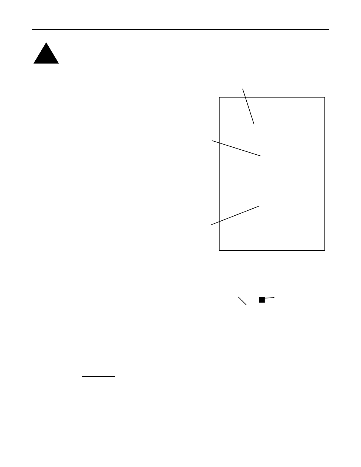
Step 3.
Look at your PISTA® Turbo Grit Pump. Decide
which side of the motor adapter the SONIC
START®Probe (Item 1) must be installed.
See Diagram 1 for orientation of the hole to be
tapped for the SONIC START®Probe (Item 1).
The SONIC START®Probe (Item 1) will stick
approximately 4-¼” out from the side of the
motor adapter.
TECHTIP: Check all equipment
for the 4-¼” clearance. It may
be necessary to rotate the
motoradaptertocreateenough
clearance for the SONIC
START®Probe (Item 1) to be located between
the motor adapter and other piece of equipment.
INSTALLATION STEPS
Diagram 1
Dome Housing Stud
Dome Housing Mount-
ing Flange
VIEWS CHANGE PER DIFFERENT STYLES OF MOTORADAPTERS
Smith & Loveless, Inc. has a patent-pending on the
SONIC START® Prime Sensing System.
DANGER: Disconnect and lock out power before servicing the equipment. Failure to
do so could result in electrical shock, serious bodily injury or death.
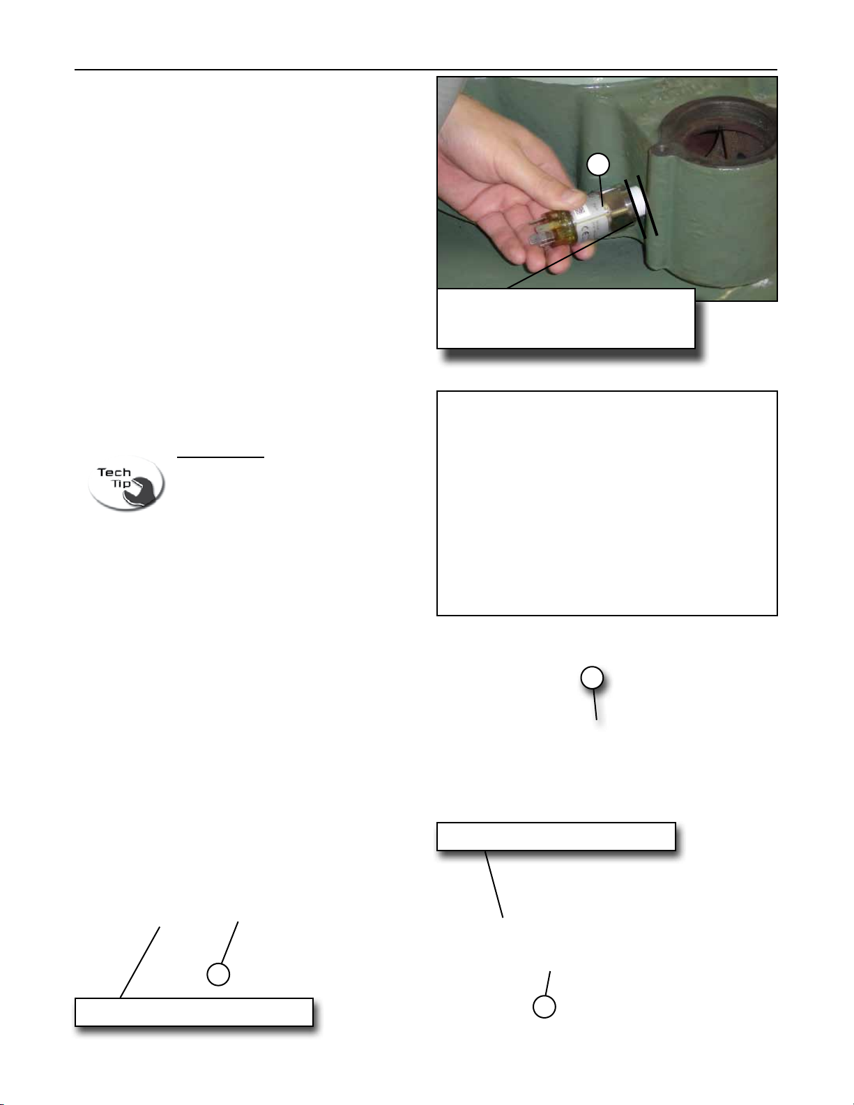
Step 2.
Disconnect the electrode grounding wire from
the existing electrode dome assembly. The
grounding wire is no longer used and can be
removed. Remove the dome assembly from
the motor adapter, Photo 1. Now continue to
Step 3 for Drilling & Tapping the motor adapter.
OR
If you already have the SONIC START® Probe
installed you do need to make sure you have
the current version of the SONIC START®
Probe. Look at the part number on the label of
theSONIC START®. If it is PN: 4L628A, remove
the existing SONIC START® Probe and skip to
Step 9. If it is PN: 4L628F, which is the current
version of the SONIC START® Probe, then skip
to Step 11.
Step 1.
Turn off and lockout power to the unit.
!
Photo 1
Dome
Grounding Wire Connector
Motor
Adapter
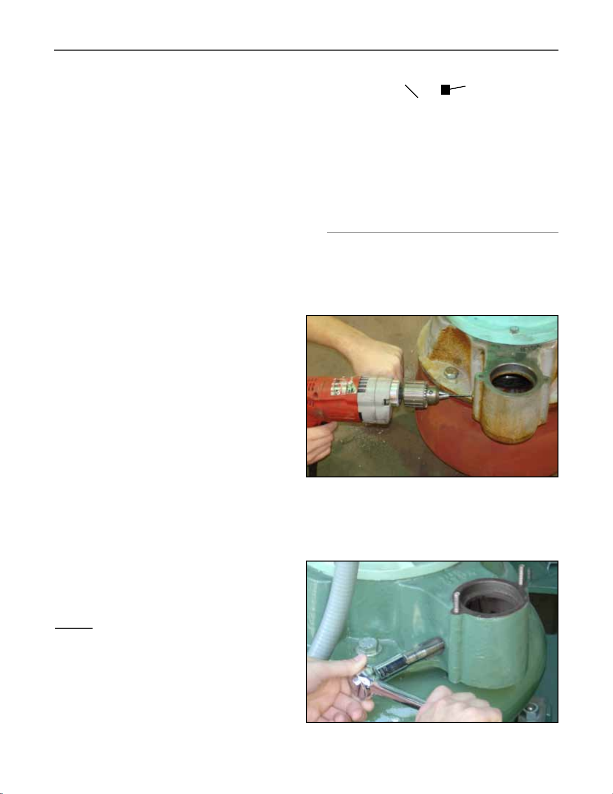
6Photo 3
Photo 2
Diagram 2
Dome Housing Stud
Dome Housing Mount-
ing Flange
VIEWS CHANGE PER DIFFERENT STYLES OF MOTORADAPTERS
Smith & Loveless, Inc. has a patent-pending on the
SONIC START® Prime Sensing System.
Step 6.
Thread the hole with the ½” NPT tap as in
Photo 3.
NOTE: Do not tap the threads too deep,
otherwise it will not seal and will create
a vacuum leak.
Step 4.
Mark the location for the SONIC START®
Probe (Item 1) on the motor adapter. See
Diagram 2 for the correct location of the
SONIC START®Probe (Item 1) . Use a
hammer and punch to make a mark at the
proper location.
Step 5.
Drill a pilot hole at the punch mark with the
3/16” drill bit (see Photo 2). Make sure the
hole is as straight as possible to make it
easier when tapping. Then drill the hole out
with the ½” drill bit, and then nish drilling
the hole with the 45/64” drill bit.
7
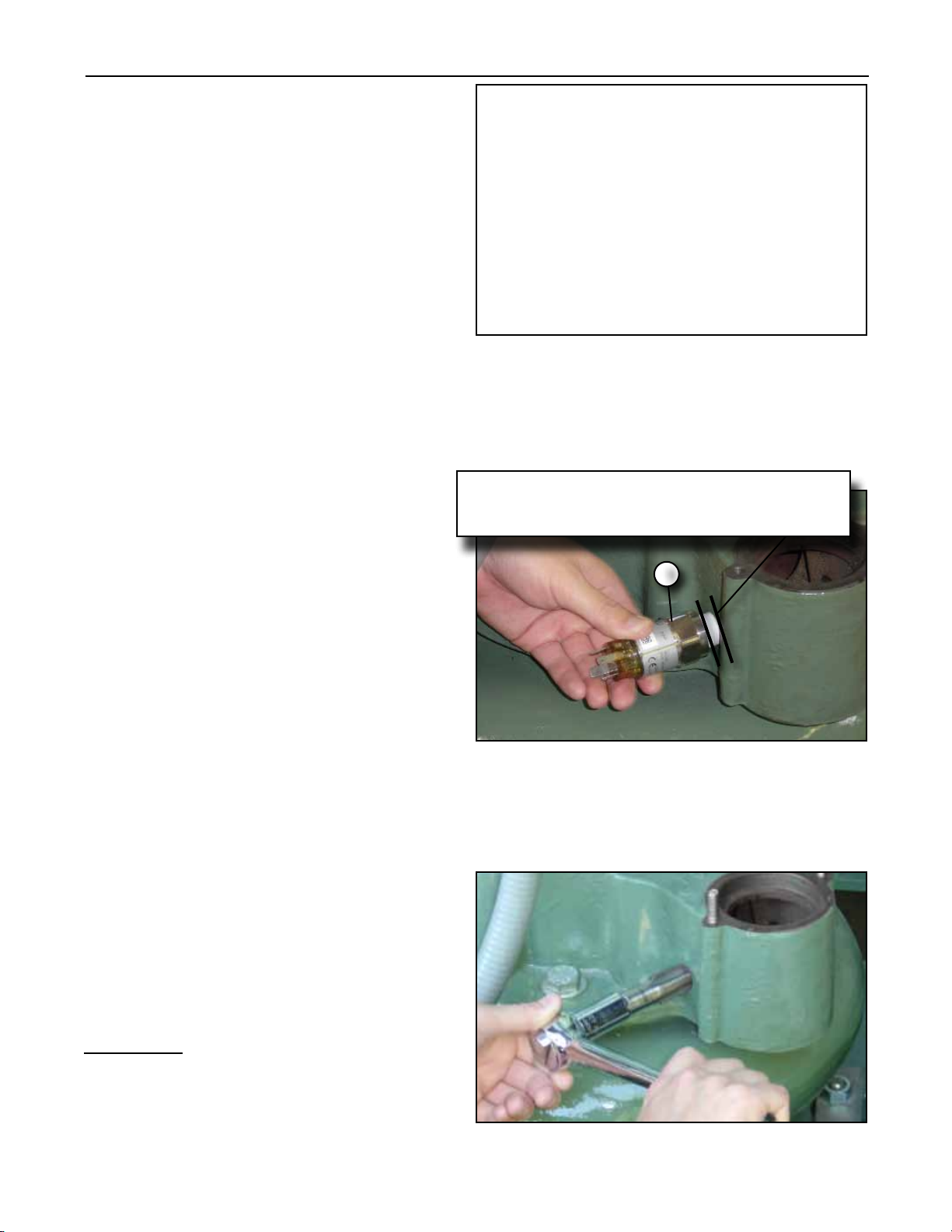
Step 8.
If the shoulder of the SONIC START®Probe
(Item 1) is more than ¼” from the motor
adapter, then the threads need to be tapped
deeper.
Remove the SONIC START®Probe
(Item 1) and insert the tap back in the hole
(Photo 6). One revolution of the tap should
make the tapped hole approximately 1/16”
deeper.
EXAMPLE: If the SONIC START®Probe
(Item 1) was 3/8” from the motor adapter,
you would want to make (2) two additional
rotations with the tap so that it will end up ¼”
or less from the motor adapter. Photo 6
Step 7.
Thread the SONIC START®Probe (Item 1)
into the tapped hole to test the depth of the
tapped hole. The shoulder of the SONIC
START®Probe (Item 1) must be ¼” or less
fromthemotoradaptertohaveproperthread
engagement, see Photo 5.
Space between lines (shoulder of SONIC START®
Probe (Item 1) & motor adapter must be 1/4”
or less.
1
Photo 5
Photo 4
Step 6 (Continued).
Turn the tap with an adjustable wrench or a
12 point 15 mm socket and socket wrench
and keep track of how many revolutions you
make with the tap. Keep the tap straight as
you are turning it. Once the end of the tap is
throughthewallofthemotoradapterandyou
havemadeatleast5 revolutions,removethe
tapfrom themotor adapter.Yourtappedhole
will look like Photo 4.
8
Photo 9A
SONIC START®Fitting Ring Item 1A
1
Photo 9
SONIC START®Fitting Ring Item 1A
Photo 9B
If additional tapping is required, retap the hole
and reinsert the SONIC START®Probe (Item
1). Check the depth and tap the hole deeper,
if necessary, to get the shoulder of the SONIC
START®Probe (Item 1) to be ¼” or less from
the motor adapter (Photo 7).
Remove the SONIC START®Probe
(Item 1). (Photo 8)
Photo 8
Photo 7
1
Space between lines (shoulder of
SONIC START®Probe (Item 1) &
motor adapter must be 1/4” or less.
Step 9.
Put Teon®tape on the SONIC START®Probe
(Item 1) threads. Make sure the Teon®tape
coversthethreadsasshowninPhoto9.Thread
the SONIC START®Probe (Item 1) into the
tapped hole.
Place the SONIC START®Fitting Ring (Item
1A) onto the end of the SONIC START®Probe
(Item 1) as seen in Photos 9A & 9B. There is
only one way it can be installed, with the more
square side closest to the prongs. Additionally,
it is cut on the inside to match the end of the
SONIC START®Probe (Item 1), which has two
90 degree corners and two rounded corners.
Make sure it ts snuggly against the SONIC
START®Probe (Item 1), as shown in
Photo 9B.
TECH TIP: Thread the Teon®
tape CCW (counterclockwise) to
thetop of thethread. Do notwrap
more than two layers of Teon®
tape on the threads.
1
1
9
Step 10.
Tighten the SONIC START®Probe
(Item1)(Photo10)sothatthetwosensing
probes run vertically inside the dome port
of the motor adapter, (see Photo 11).
Step 11.
If you already had the SONIC START®
Probe (Item 1) installed, reuse the
existing SONIC START®Probe’s (Item
1) electrical tting (Item 1C) and wiring,
and connect it to the SONIC START®
Probe’s (Item 1) and Skip to Step 41.
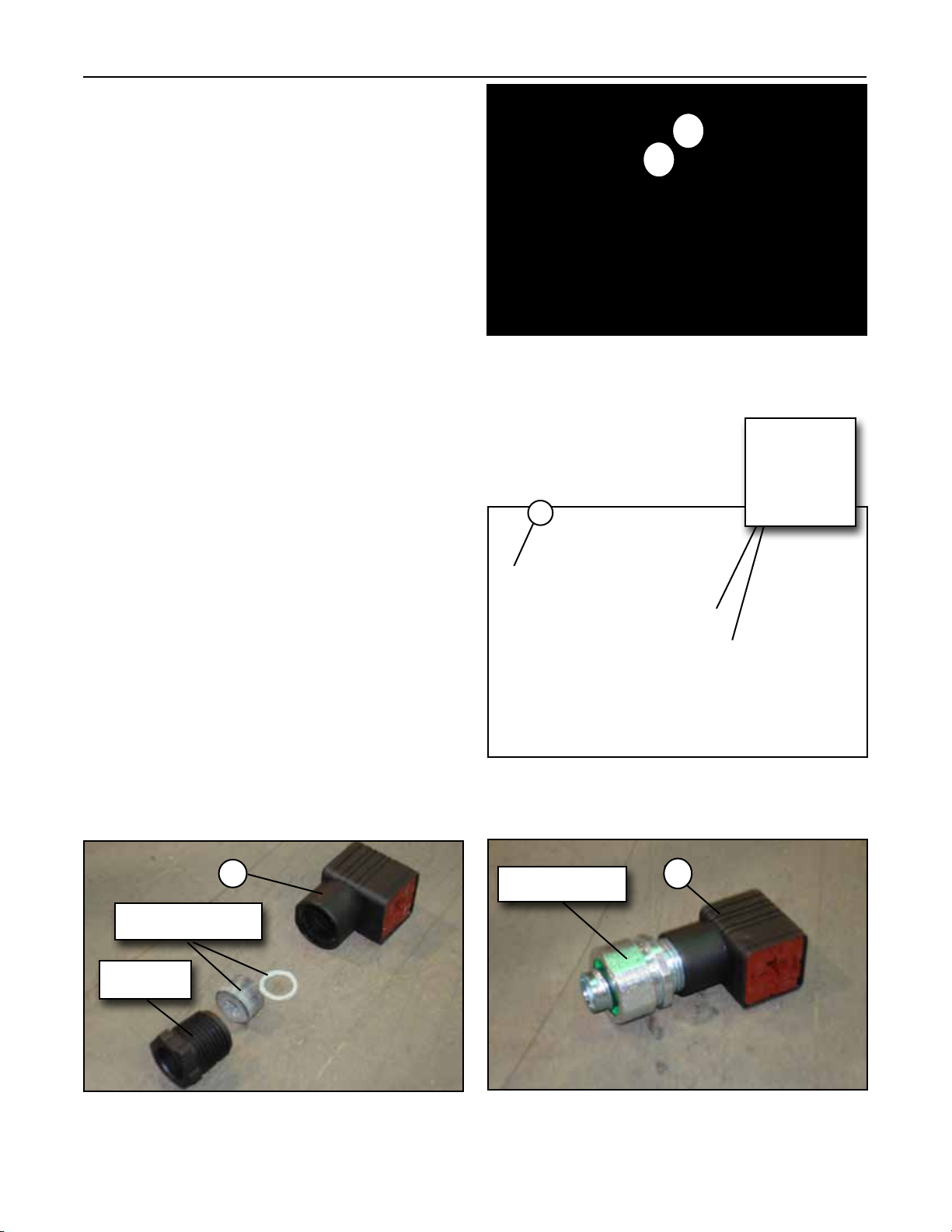
If you have an electrode dome, remove
the cord grip and grommet portion of
the SONIC START® Probe’s electrical
tting (Item 1C). See Photo 12.
Step 12.
Install a conduit tting (not included in
this kit) to the ½” conduit threads on
the SONIC START® Probe’s electrical
tting (Item 1C). See Photo 13. Photo 11
1
Make sure the
sensing probes
run vertically
inside the
dome.
Photo 10
Photo 13
1C
Photo 12
1C Conduit Fitting
1A 1
Grommet & O-Ring
Cord Grip

10
Step 13.
Open up the SONIC START® Probe’s
electrical tting (Item 1C) by prying the plug
out from the body. See Photo 14. A small
screw driver can be used to pry out the plug.
Step 14.
The SONIC START®Probe’s electrical tting
can now be wired. See Photo 15. Take one
end of new electrical wire (not supplied
with this kit) and connect one Power wire
to Pin 1, a second Power wire to Pin 2 and
the Ground wire to the Ground Pin on the plug
of the SONIC START®electrical connector
(Item 1C), see Photo 16.
Photo 14
Photo 16
1C
Plug
Photo 15
Plug
1C
Ground Wire
Wire 1 Wire 2
Plug
Ground Pin
Pin 1 Pin 2
Pin Not Used
Plug
11
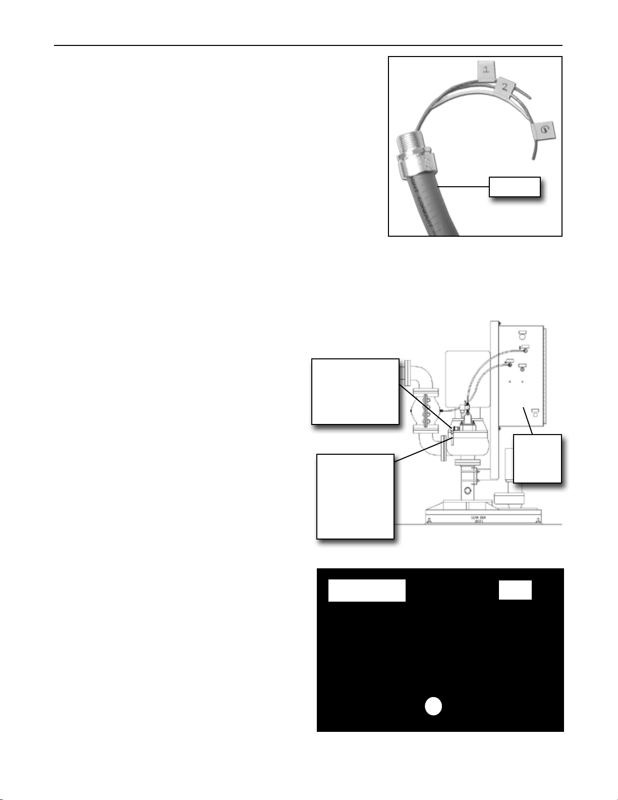
Step 15.
The other end of the new wires needs to be
labeled with a piece of masking tape Pin 1, Pin
2 or Ground Pin (depending on what the wire
is tied to) so that the wires can be connected to
the correct location, see Photo 17. There are
4 Pins on the plug and only three Pins will be
used, see Photo 15.
Step 16.
Run the wire through the SONIC START®
electrical connector (Item 1C) and conduit
tting. Make sure there is enough wire to run
from the SONIC START® electrical connector
(Item 1C) to the required location for
connection. This may be the vacuum priming
panel, see Diagram 3, or the system’s control
panel, or another location. Diagram 3 is for
reference only. You must determine how your
installation is currently wired for either the
Electrode or SONIC START® Probe (Item 1).
Wiring connections are dependent upon what
your unit has currently installed. Your new
conduit and wiring from the SONIC START®
Probe (Item 1) will need to tie into the socket
of your existing Electrode Relay or SONIC
START® Operating Module (Item 2)
Step 17.
Insert the plug back into the SONIC START®
Probe’s electrical tting (Item 1C). See Photo
18. Install the SONIC START® electrical tting
(Item 1C) onto the SONIC START® Probe
(Item 1) See Photo 19.
1/2” Conduit (Not
supplied by S&L) Run to
Main Control Panel
or location where the
existing Electrode
Relay or Sonic Start®
Operating Module
is currently located.
Every installation is
different.
SONIC START®
Probe with at-
tached electrical
connector (Item
1C).
Vacuum
Priming
Panel
Diagram 3
Photo 18
Photo 17
Conduit
Plug
1C
Conduit Fitting

12
Step 18.
Tighten the SONIC START® Probe’s electrical
tting (Item 1C) onto the conduit (not included
in this kit) that will run to the existing electrode
relay or SONIC START® Operating Module
socket. (Photo 19).
Step 19.
Now run conduit (not included in this kit) from the
SONIC START® Probe’s electrical connector
(Item 1C) to the panel with the Electrode
Relay or SONIC START® Operating Module
socket. In Step 16, you located the relay or
Operating Module. Cable Ties (Item 10) have
been included for use with the conduit if your
installation requires.
Photo 20
Photo 19
Conduit
Fitting
Conduit
1C
2
1C
1
1

13
NOTE: If you already have the SONIC START®priming system installed, skip
to Step 41.
RELAY 2. (S&L P/N: 4L408)
A larger clear relay with a red light that
indicates when the pump is primed (see
Relay 2 in Photo 21). If you are replacing
this type of electrode relay, go to step 25.
RELAY 3. (S&L P/N: 4L408H)
A black plastic cased relay that is plugged
into an 8-pin socket (see Relay 3 in
Photo 21). If you are replacing this type of
electrode relay, go to step 33.
Relay 1
Relay 2 Relay 3
Photo 21
DANGER: Disconnect and lock out power before performing any electrical work.
Failure to do so could result in electrical shock, serious bodily injury or death.
WARNING: All electrical work should be performed by a qualied electrician and per
all applicable codes. Failure to do so may result in severe bodily injury or death.
!
!
Step 20.
Now the wiring for the electrode relay must be
modied in order to use the new SONIC START®
Operating Module (Item 2). There are three
differenttypesofelectroderelaysthathavebeen
usedonSmith&LovelessTopMountedPISTA®
Turbo Grit Pump, see Photo 21 . The three
electrode relays from oldest to most recent are:
RELAY 1. (S&L P/N: 4L264)
A small, clear relay with a resistor, diode,
and capacitor in the socket wiring (see
Relay 1 in Photo 21. If you are replacing
this type of electrode relay, go to step 21.
Socket 1 Socket 2 Socket 3
Electrode Relays
14
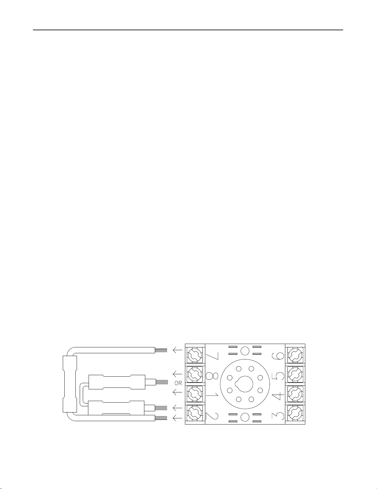
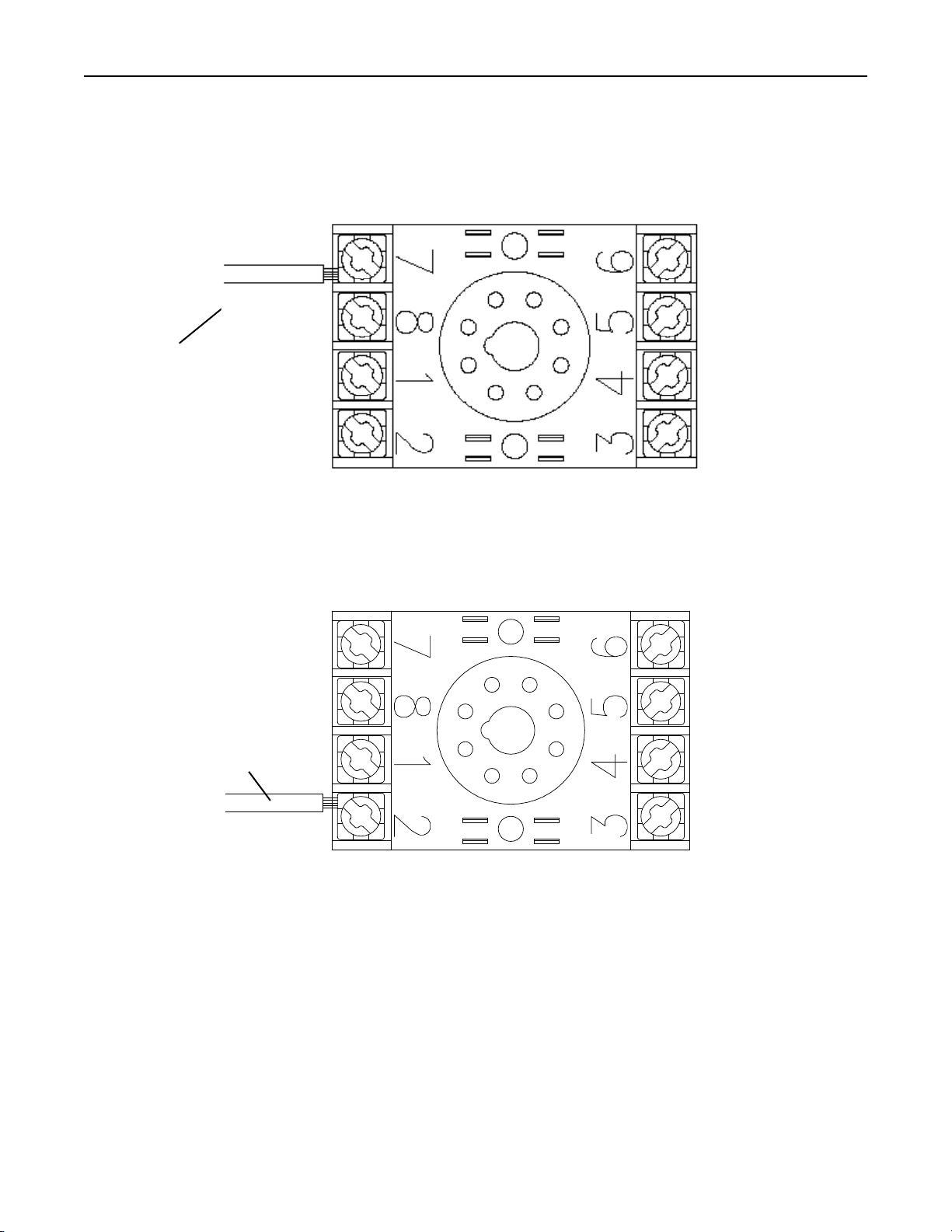
Steps 21 to 24 are for rewiring the socket of the small clear relay with a resistor, diode, and
capacitorinthesocketwiringonly.(IfyourrelaylookslikeRelay1inPhoto22,usesteps21to24.)
Relay 1
Photo 22
but keep any other wires connected to pin 1 or
pin 8. Do not reuse any wires with a resistor,
capacitor, or diode.
Step 21.
Removetheclearrelayfromitssocket.Remove
any wires that are connected to pin 2 or pin 7
of the electrode relay socket. A wire from pin 2
will go to either pin 1 or pin 8. Remove this wire,
15
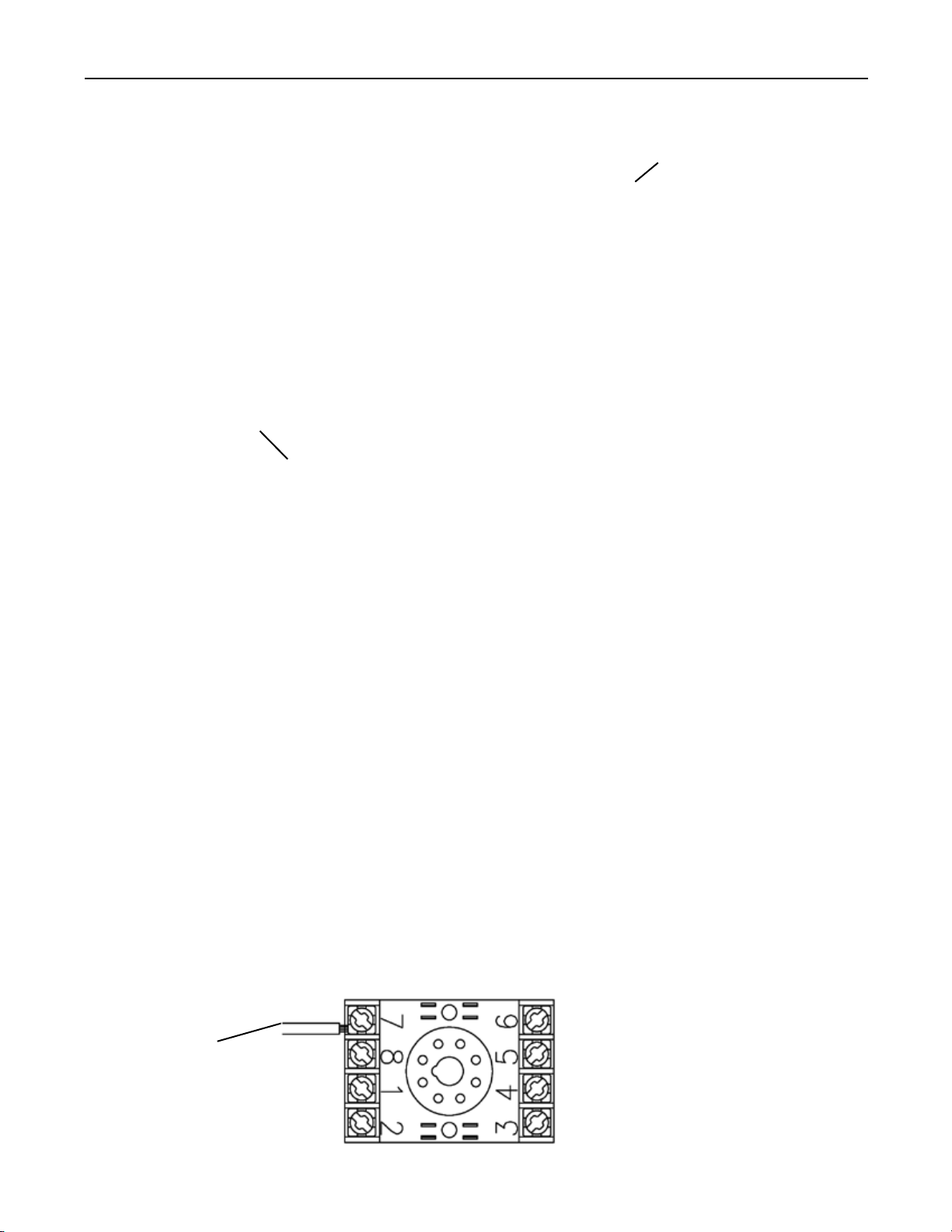
Step 22.
Look at the control circuit breaker and see what wire number is terminated on the load (secondary)
side of the control circuit breaker. Run a wire from Pin 7 of the socket to one of the terminal blocks
or other connections with the same number as the wire terminated on the load (secondary) side
of the control circuit breaker.
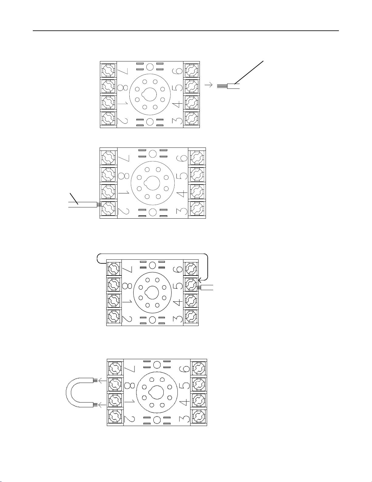
Step 23.
Run the wire from Pin 1 of the SONIC START® Probe’s electrical tting (Item 1C) to Pin 2.
Step 24.
Run the wire from Pin 2 of the SONIC START® Probe’s electrical tting (Item 1C) to neutral and
run the ground wire to ground.
Wire from pin 1 of SONIC
START® Probe’s electrical
tting.
To Control
Power

16
Relay 2
Steps 25 to 32 are for rewiring the socket of the larger clear electrode relay only. (If
your relay looks like Relay 2 in Photo 23, use steps 25 to 32.)
Step 25.
Remove any wires from pins 3 and 4. Typically they are connected to the terminal strip.
Consult your wiring diagram for the correct wire number.
Step 26.
Remove the wire from pin 2 and connect it to the wire from pin 2 of the SONIC START® Probe’s
electrical tting (Item 1C).
Photo 23
Remove from pin 2
and connect to the
wire from pin 2 of
the SONIC START®
Probe’s electrical
tting (Item 1C).
17
Step 27.
Remove the wire from Pin 5 and connect it to the Ground wire from the SONIC START® Probe’s
electrical tting (Item 1C).
Step 28.
Connect the wire from pin 1 of the SONIC START® Probe’s electrical tting (Item 1C) to Pin 2.
Step 29.
Move any wire(s) from Pin 7 to Pin 5. These pins are on the opposite side of the socket, so it
may be necessary to run a new wire or to wire nut another piece of wire onto it to reach.
Step 30.
If there is a jumper wire between Pins 1 and 8 remove it.
Wire from
pin 1 of
the SONIC
START®
Probe’s
electrical
tting
Remove the wire from
pin 5 and connect it to
the ground wire from the
SONIC START® Probe’s
electrical tting (Item 1C).

18
Step 31.
If there are any wire(s) on Pin 1, move them to Pin 8.
Step 32.
Look at the control circuit breaker and see what wire number is terminated on the load (sec-
ondary) side of the control circuit breaker. Run a wire from Pin 7 of the socket to one of the
terminal blocks or other connections with the same number as the wire terminated on the load
(secondary) side of the control circuit breaker.
To Control
Power

19
Steps 33 to 39 are for rewiring the socket of the black plastic 8-pin electrode
relay only. (If your relay looks like Relay 3 in Photo 24, use steps 33 to 39.)
Step 33.
Remove any wires from Pins 6 and 8. Typically they are connected to the terminal strip.
Consult your wiring diagram for the correct wire number.
Step 34.
Remove the wire from Pin 2 and connect it to the wire from Pin 2 of the SONIC START®Probe’s
electrical tting (Item 1C).
Relay 3
Photo 24
Remove from pin 2
and connect to the
wire from pin 2 of
the SONIC START®
Probe’s electrical
tting (Item 1C).
20
Step 35.
Remove the wire from Pin 5 and connect it to the ground wire from the SONIC START®Probe’s
electrical tting (Item 1C).
Step 36.
Connect the wire from Pin 1 of the SONIC START®electrical tting (Item 1C) to Pin 2.
Step 37.
If there is a jumper wire between Pins 1 and 7, remove it.
Step 38.
If there are any wire(s) on Pin 7, move them to Pin 1.
Step 39.
Look at the control circuit breaker and see what wire number is terminated on the load (sec-
ondary) side of the control circuit breaker. Run a wire from Pin 7 of the socket to one of the
terminal blocks or other connections with the same number as the wire terminated on the load
(secondary) side of the control circuit breaker.
Wire from pin 1 of
the SONIC START®
Probe’s electrical
tting (Item 1C)
Remove the wire from
Pin 5 and connect it to
the ground wire from
the SONIC START®
Probe’s electrical tting
(Item 1C)
To Control
Power
Other manuals for Sonic Start Streamline
1
This manual suits for next models
1
Table of contents
Popular Water Pump manuals by other brands

Little Giant
Little Giant 5.5-ASPA Series owner's manual

STREET WISE
STREET WISE streetwise instructions

aqua technix
aqua technix AQUA Splash Installation and operating instructions

red lion
red lion RL-WCS50TA-24 owner's manual

SPX FLOW
SPX FLOW PE10 Series quick start guide

Little Giant
Little Giant PE-1H-PW Series manual

Little Giant
Little Giant 8-CBM manual

Aqua One
Aqua One CUF Series instruction manual

Great Plains Industries, Inc.
Great Plains Industries, Inc. M-150S Operation guide

Welbilt
Welbilt Multiplex WBK10X instruction sheet

Astral Pool
Astral Pool MICRO Installation and maintenance instructions

Alfalaval
Alfalaval LKH Prime 20 instruction manual


