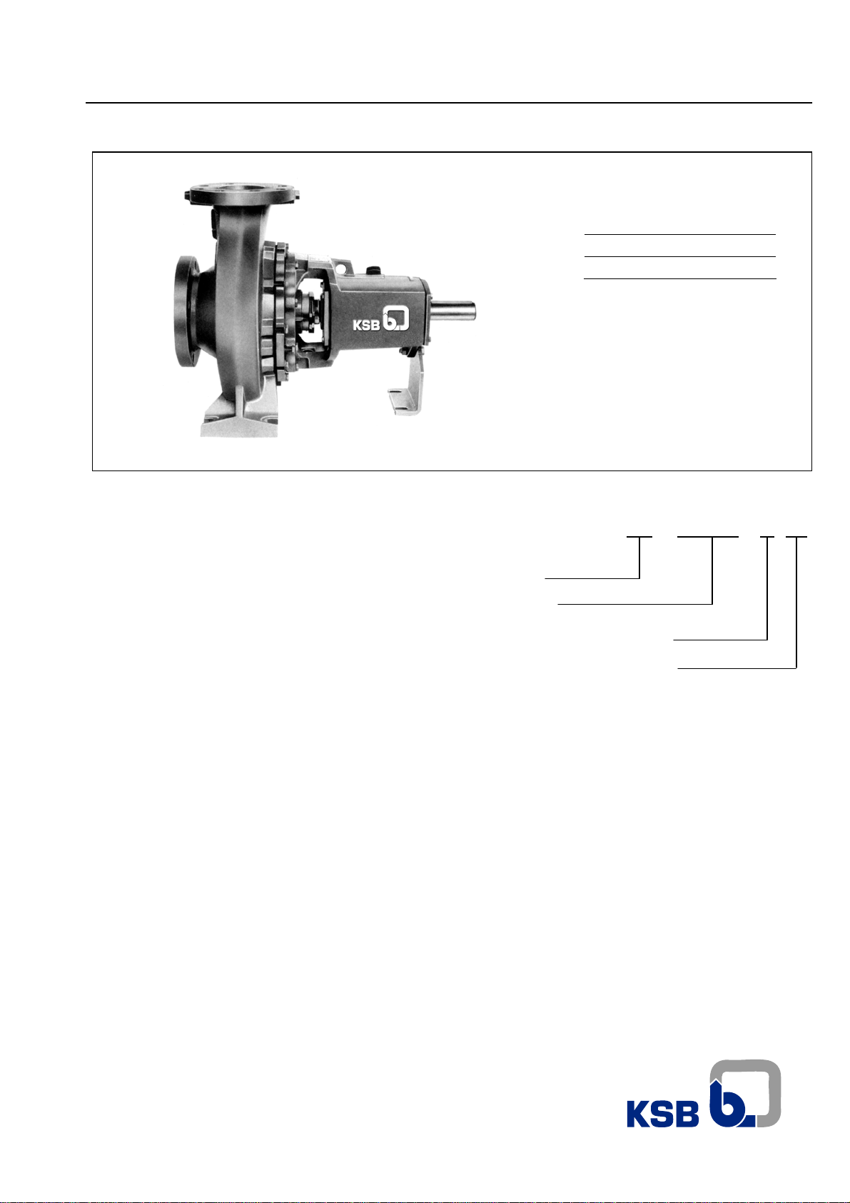
7
Meganorm
f) Curves and accessories, when needed should be
designed and installed reducing pressure losses to a
minimum, i.e. always prefer long or medium radius
curves.
g) The suction line flange should fit to the pump suction
flange without any stress or tension and without applying
any kind of force to the casing. The pump should never
be an anchor point for the suction pipeline. If this
condition is not observed a misalignment may happen,
originating cracks on pump parts and/or other severe
damages.
h) On installations equipped with foot valve, observe that the
free passage area should be 1.5 times the cross sectional
area of the suction pipeline. Normally coupled to the foot
valve there should be a suction strainer with a free
passage area 3 to 4 times larger than the cross sectional
area of the suction pipeline.
i) When the liquid being pumped has large temperature
variations, expansion joints should be installed preventing
the effects of contractions and expansions of the suction
pipeline on the pump.
j) With positive suction, it is advisable to install an inlet
valve to close the flow to the pump when necessary.
During the pump operation it should stay totally open. A
suction with a common header for several pumps should
have an inlet valve for each pump and the connection
between the header and each suction line should be
made with line angle changes less than 45 degrees. In all
these applications of gate valves, the valve stems should
be directed either horizontally or vertically downwards.
k) To prevent turbulence, leakage of air, sand or mud at the
pump suction, all recommendations of the HYDRAULIC
INSTITUTE referred to the these types of installation
should be strictly observed.
l) Even if the coupling alignment has been checked before
tightening, it has to be repeated after the final tightening
of the suction pipeline.
m) To facilitate the mounting of the suction pipeline and the
fitting of the parts, install as necessary, flexible joints of
the following types: Dresser, common or special with tie
bolts.
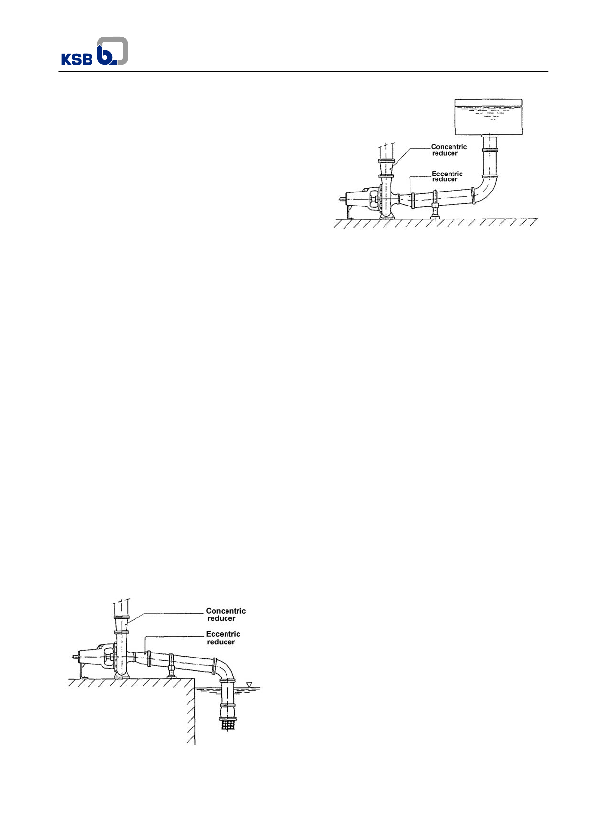
Fig.10 – Negative suction
Fig.11 Positive suction
9.6 Discharge pipeline – Recommendations
To install the discharge pipeline, please follow the instructions
below:
a) If the overpressures caused by the returning of the liquid
in long pipe lines, exceed the limits specified for the line
and the pump, water hammer control devices should be
installed on the discharge pipe line.
b) When the diameters of the pump and pipeline flanges are
different, the connections should be done through a
concentric reduction.
c) On the points where it is necessary to bleed the air in the
pipeline, vent valves should be installed.
d) Install a discharge valve, if possible immediately after the
discharge nozzle of the pump in order to properly control
the flow rate and pressure or to prevent driver overloads.
e) When a non-return valve is installed, it should be mounted
between the pump and the discharge valve, prevailing this
condition over item D.
f) Tie mounting joints should be installed to absorb the
system reaction forces, originated on the applied loads.
g) Safety valves, pressure relief devices and other
operational valves not included up to now, should be
installed as necessary for adequate operation of the
pipeline.
h) The recommendations for the suction pipeline described
on items A, B, F, G are also valid for the discharge
pipeline.