Airetool 720 Series Instruction and safety manual

For additional product information visit our website at http://www.apextoolgroup.com
Operating & Service Manual
90014-IM
05/11/2011
720 Series
Airetrol Rolling Motor
Model Number Part Number (Order)
720-550-B 8405391
720-1800-B 8405383
720-2500-B 8405541
Airetool®

2

3
Safety Recommendations
FOR YOUR SAFETY AND THE SAFETY OF OTH-
ERS, READ AND UNDERSTAND THE SAFETY
RECOMMENDATIONS AND OPERATING IN-
STRUCTIONS BEFORE USING THIS TOOL.
For additional information on eye and face protec-
tion, refer to Federal OSHA Regulations, 29 Code of
federal regulations, Section 1910.133 Eye and Face
Protection, and American National Standards Insti-
tute, ANSI A87.1, Occupational and Educational Eye
and Face Protection Z87.1 is available from the Ameri-
can National Standards Institute, 11 West 42nd Street,
New York, NY 10036.
Hearing protectors are required in high noise areas,
85 dBA or greater. The operation of tools and equip-
ment in the area, reflective surfaces, process noises
and non-resonant structures can substantially con-
tribute to and increase the noise level in the area.
Excessive air pressure above 9o psig or worn motor
components can also increase sound level emitted
by tool. Proper hearing conversation measures, in-
cluding annual audiograms and training in the use
and fit of hearing protection devices may be neces-
sary.
Some individuals are susceptible to disorders of the
hands and arms when exposed to task which involve
highly repetitive motions or vibration. Those individu-
als predisposed to vasculatory or circulation problems
may be particularly susceptible. Cumulative trauma
disorders such as Carpal Tunnel Syndrome and Ten-
donitis can be caused by repetitions, forceful exer-
tions of the hands and arms. These disorders de-
velop gradually over periods of weeks, months and
years.
* Tasks should be performed in such a manner
that the wrists are maintained in a neutral position
which is not flexed, hyperextended or turned side to
side.
* Stressful postures should be avoided and can
be controlled through tool selection and work loca-
tion. Any user suffering from prolonged symptoms of
tingling, numbness, clumsiness or weakened grip,
nocturnal pain in the hand or any other disorder of
the shoulders, arms, wrists or fingers is advised to
consult with a physician. If it is determined that the
symptoms are job related or aggravated by move-
ments and postures dictated by the job design it may
be necessary for the employer to take steps to pre-
vent further occurrences. These steps might include,
but are not limited to repositioning the work piece or
redesigning the work station, reassigning workers to
other jobs, rotating jobs, altering work pace and/or
changing the type of tools used so as to minimize
stress on the operator. Some tasks may require more
than one type of tool to obtain the optimum operator/
tool/task relationship.

4
Safety Recommendations
The following recommendations will help reduce or
moderate the effects of repetitive work motions and/
or extended vibration exposure.
* Use a minimum hand grip force consistent with
proper control and safe operation.
* Keep wrists as straight as possible.
* Keep body and hands warm and dry.
* Avoid anything that inhibits blood circulation
- Smoking Tobacco
- Cold Temperatures
- Certain Drugs
* Avoid highly repetitive movements of hands
and wrists, and continuous vibration exposure.
FOLLOW GOOD MACHINE SHOP PRACTICES.
ROTATING SHAFTS AND MOVING COMPO-
NENTS CAN ENTANGLE AND ENTRAP, AND CAN
RESULT IN SERIOUS INJURIES. NEVER WEAR
LONG HAIR, LOOSE FITTING CLOTHES,
GLOVES, TIES OR JEWELRY WHEN WORKING
WITH OR NEAR THE EQUIPMENT.
Work gloves with vibration reducing liners and wrist
supports are available from some manufactures of
industrial work gloves Tool wraps and grips are also
available from a number of different manufacturers.
These gloves, wraps and wrist supports are designed
to reduce and moderate the effects of extended vi-
bration exposure and repetitive wrist trauma. Since
they vary widely in design, material, thickness vibra-
tion reduction and wrist support qualities, it is recom-
mended the glove manufacturer be consulted for
items designed for your specific application. WARN-
ING! Proper fit gloves is important. Improperly
fitted gloves may restrict blood flow to the fin-
gers and can substantially reduce grip strength.
A booklet , Assembly Tool Ergonomics, is available
free of charge by writing the following address:
Cooper Power Tools
P. O. Box 40430
Houston, TX 77240 USA
713-462-4521
Please request form No. 60669.
For more information on the safe use of portable air
tools, see the latest edition of ANSI B186.1, Safety
Code for Portable Air Tools, available from the Ameri-
can National Standards Institute, Inc., 11 West 42nd
Street, New York, NY 10036.
This information is a compilation of general safety
practices obtained from various sources available at
the date of production. However, Cooper Power Tools
does not represent that every acceptable safety prac-
tice is offered herein, or that abnormal or unusual
circumstances may not warrant or require additional
procedures. Your work may require additional spe-
cific safety procedures as required by your company.
WARNING LABELS
The warning labels found on these tools are an es-
sential part of the product. Labels should not be
removed. Labels should be checked periodically for
legibility. Replace warning labels when missing or
when the information can no longer be read. Replace-
ment labels can be ordered as any part.

5
Operating Instructions
OPERATION
The Model 720 AIRETROL is a trigger operated roll-
ing control with an automatic, torque controlled re-
versal. It is designed for use with regulated, filtered
and lubricated 90 psig air (measured at the tool in-
let), but can be used at lower pressures to lower the
minimum torque setting if required (with some loss of
free speed). The operator pulls the trigger to start the
tool (before engaging the expander mandrel in soft
tubes to avoid “staking” ) and holds it until the entire
rolling operation is completed. The tool expands to a
preset torque, reverses automatically and backs out
to release the mandrel. The tool stops and resets
when the operator releases the trigger between tubes.
If necessary, the tool can be started in reverse by
unscrewing the clutch housing (32) three or four turns
and pulling back gently on the tool before pulling the
trigger.
AIRETROL CLUTCH ADJUSTMENT
Remove clutch housing (32) (left hand threads) and
spindle/clutch assembly from tool, taking care to avoid
loss of push rod (52) or spring (51). Hold clutch driver
(58) with a 3/8” wrench and turn the adjusting nut
(39) with a 3/4” open end wrench (right hand thread).
Compressing the spring increases the torque setting.
Reinstall the spindle/clutch assembly and the clutch
cover carefully to avoid damaging the push rod. For
very light torque settings, the adjusting nut (39) can
be locked to the spindle with a #8-32 x 3/16” nylon
tipped set screw (not included).
CHANGING THE TORQUE REGULATING SPRING
Remove clutch housing (# 32) (left hand thread) and
spindle/clutch assembly from the tool. Remove the
socket head cap screw (# 46) and the chuck assem-
bly (35, 34, 33, 31, 30 & 29), wave washer (36), bear-
ing (37), c-ring (38), lock nut (39), lock washer (40
and regulating spring (41 and install the desired regu-
lating spring and reassemble parts in reverse order.
Make sure that the wave washer (36) is centered on
the bearing guard (35) (1/4” chuck) or chuck body
(34) (3/8” chuck) before securing the chuck. With the
1/4” chuck, it is important to always keep the screw
(46) tight to avoid excessive wear to the spindle (48)
and the chuck body (34). Set and test tool for proper
reversal before resuming operations - SEE CAUTION.
I
F THE CLUTCH IS ADJUSTED OVER THE MAXI-
MUM POWER OUTPUT OF THE TOOL, THE
CLUTCH WILL NOT FUNCTION
AND THE TOOL
WILL OPERATE LIKE A STALL TYPE TOOL. ALSO,
IF THE TOOL IS BEING OPERATED AT ITS UP-
PER TORQUE LIMITS, A DROP IN AIR PRESSURE
COULD CAUSE THE CLUTCH NOT TO FUNCTION
DUE TO A LOSS OF MOTOR POWER AND THE
TOOL WILL FUNCTION LIKE A STALL TYPE TOOL.
OPERATIONAL CHECK: GRIP TOOL SECURELY
AND BE PREPARED TO COUNTERACT STALL
TORQUE IN CASE THE CLUTCH IS IMPROPERLY
ADJUSTED.
AIR SUPPLY
The tool is designed to operate on 90 psig maximum
air pressure. The air pressure should be checked at
the tool’s inlet when the tool is running. An automatic
in-line filter-lubricator is required. This will sustain the
tool with clean, lubricated air; keeping it in sustained
operation; and increase tool life.
For maximum performance, use a 1/4”I.D. minimum
air hose up to 8 ft.in length. If additional length is re-
quired, a 3/8”I.D. or larger hose should be connected
to the 1/4”hose (or use 3/8”I.D. hose or larger the
full length).
The air hose should be cleared of accumulated dirt
and moisture,. Then pour one half (1/2) teaspoon of
10W oil into the tool’s air inlet before connecting the
hose to the tool. A new hose should be similarly lubri-
cated before placing in service. The tool should be
cycled several times to disperse the oil before rolling
tubes.
LUBRICATION
The in-line lubricator should be regularly checked and
kept filled with a good grade of 10W machine oil.
Application of the tool should govern how frequently
it is greased. It is recommended that the idler gears
receive a generous amount of No. 2 Moly grease af-
ter every 40 hours of operation. The clutch housing
(left hand threads) and the clutch/spindle/driver as-
sembly must be removed and the grease applied
through the hex in the spider.

6
Service Instructions
DISASSEMBLY
Clamp the handle (70) in a soft jawed vise and unscrew
(left hand threads) the clutch housing (32) and remove the
shaft/clutch assembly (48, 58 & 57). Pull out the push rod
(52) and spring (51). Unscrew the gear train (59) from the
handle (70) assembly. The motor (60) and valve assembly
(1 thru 6) can now be removed from the handle (70). See
the following paragraphs for disassembly instructions for
the various sub-assemblies.
HANDLE MAINTENANCE
Unscrew the air inlet busing (80) and remove the air inlet
screen (77), spring (76) and throttle valve (75). The air in-
let screen should be washed in solvent and blown out in
reverse of normal air flow. Replace the screen if clogged
or torn. Inspect the throttle valve seal (75) and replace the
valve if necessary. Inspect the “O”rings (78 & 79) and re-
place if necessary. If replacement of the trigger (71) or
throttle pin (72) becomes necessary, check that the spring
pin (73) will clear the back of the trigger slot before install-
ing the pin. If there is interference, grind off enough of the
throttle pin (72) so that the trigger will clear. If this is not
done, the tool will not shut off when the trigger is released.
Before putting the throttle valve (75) back into the tool, push
the throttle pin (72) all the way forward and make sure that
the notch in the end of the throttle pin is vertical so that the
throttle pin will engage the throttle valve properly after as-
sembly.
CLUTCH DISASSEMBLY
Disassemble per instructions in
CHANGING THE TORQUE
REGULATING SPRING
. Remove ring (57), clutch driver
(58) and washers (49 & 50). Drive out the 1/16”x 3/16”
spring pin (55) and remove the washer (42), cam (43), six
balls (47), trip (56), spring bushing (54), spring (53), Tru
Arc (44) and clutch (45).
GEAR CASE ASSEMBLY
A. Single Reduction
The spider (14) should be pressed out of the rear of the
gear case (13). Remove the retainer ring (11) and press
the bearing (12) out of the front of the gear case (13).
If replacement of the idler gear pins (15) is necessary, they
should be pressed out of the rear of the spider (14) . See
Figure 1 for replacement pin height.
B. Double Reduction
Both spiders (4 & 5) should be removed from the rear of
the gear case (3). Remove the retainer ring (1) and press
the bearing (2) out of the front of the gear case (3).
If replacement of the idler gear pins (5 & 8) is necessary,
they should be pressed out of the rear of the spiders (4 &
7). See Figure 2 for replacement pin height.
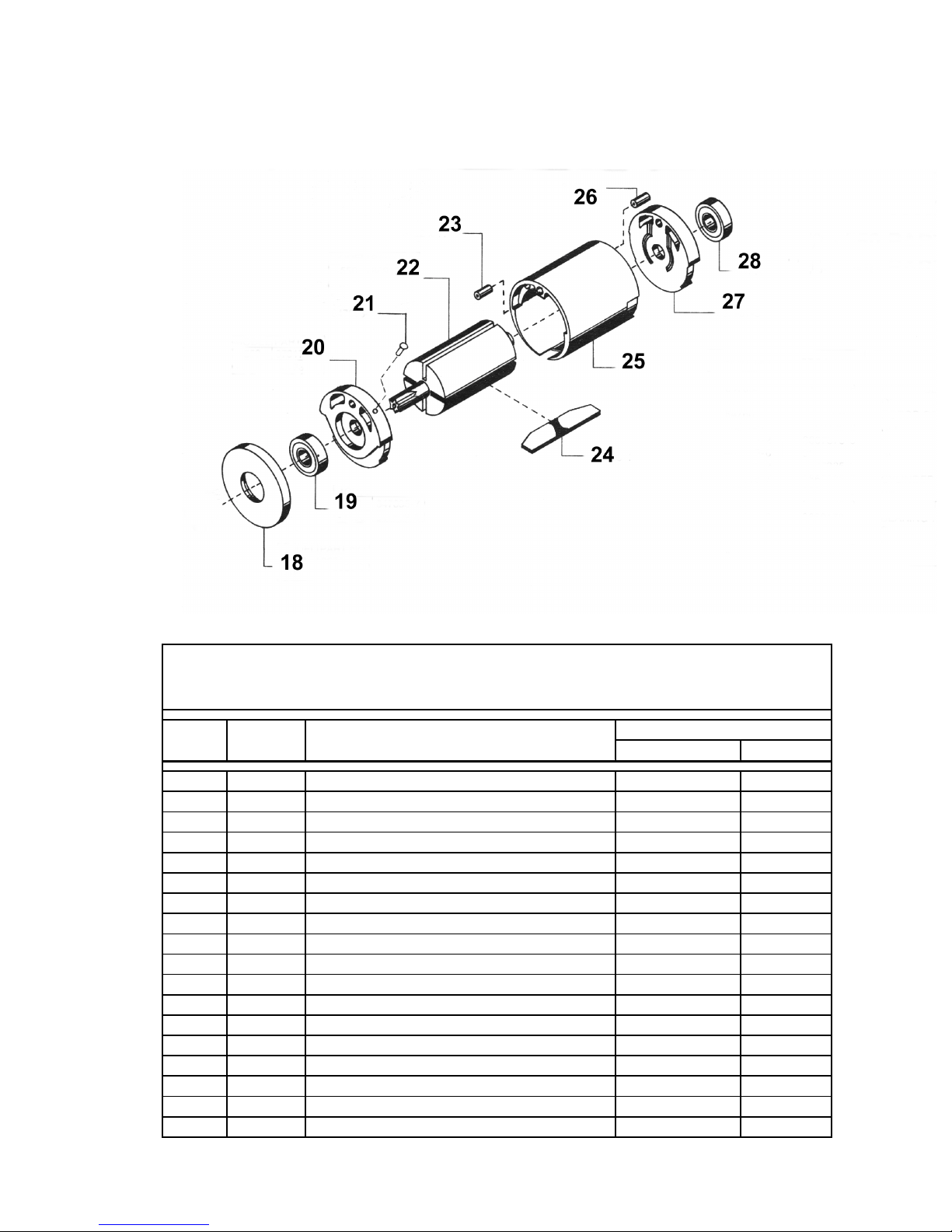
MOTOR DISASSEMBLY
Slip the front bearing plate (20) and bearing (19) off the
front of the rotor (22) and remove the cylinder (25) and four
(4) rotor blades (24). Set the rear bearing plate 27) on the
vise jaws with the rotor (22) hanging down. Use a 7/32”
punch to drive the rotor (22) out of the rear rotor bearing
(28).

7
REASSEMBLY IN GENERAL
All parts should be washed in a solvent and inspected for
damage or wear. Particular attention should be given to all
bearings, gears, gear pins and rotor blades as failure of
these parts could cause damage to more expensive parts.
Rotor blades should be replaced if they measure less than
3/16”on either end. Inspect and replace any “O”rings or
seals that show signs of wear or deterioration. All gears,
gear pins and open bearings should receive a generous
amount of No. 2 Moly grease during reassembly. When
assembling the gear case to the back head, the case should
be torqued to 300/325 in. lbs. (33.9/36.7 Nm).
Do Not Over-
tighten
, as it can distort the valve assembly and cause the
valve to stick. Reassembly of all of the various sub-assem-
blies is in the reverse order of disassembly; however, the
following paragraphs list some of the more important reas-
sembly procedures.
CLUTCH ASSEMBLY
During the reassembly of the clutch assembly, all parts
should receive a thin coating of a mixture of 10W machine
oil and No. 2 Moly grease. The clutch (45), Tru Arc (44),
spring (53), spring bushing (54), trip (56), balls (47), cam
(43) and washer (42) must be in position on the clutch shaft
(48) before installing the spring pin (55). Install the spring
pin (55) so it is below the surface at both ends. The instal-
lation of the balls (47) can be simplified by filling the ball
slots in the shaft (48) with grease if desired.
MOTOR ASSEMBLY
Install the rear rotor bearing (28) into the rear bearing plate.
Press the bearing plate assembly (press on the bearing’s
inner race) onto the rear rotor shaft until there is approxi-
mately .001”clearance between the rear bearing plate and
the rotor. Install the cylinder (25) with the slotted end to-
ward the front bearing plate.
If a new rotor or complete motor assembly is to be installed,
first install with RC609 Loctite, a push rod guide (61) - with
the countersunk end in first, and the other end flush with
the end of the rotor.
VALVE ASSEMBLY
Install valve sleeve (66) with Loctite RC609. The deepest
notch (5/32”deep) in the sleeve must be flush with the
valve insert (64) at the end adjacent to the motor package
and the 1/16”diameter hole must be centered in the slot.
Allow Loctite to cure per instructions on Loctite container.
CLEAN sleeve thoroughly before installing the valve spool
(67). The spool must move freely with the valve washer
installed. Orient spool stop (62) as shown, and install pin
(65) flush with the inside of the spool stop.
PUSH ROD
It is essential that the push rod be straight and that the
ends be uniformly rounded and free from burrs, or erratic
operation can result. The length of the push rod (52) deter-
mines the location of the valve spool when the tool is run-
ning forward and has been sized to be used without trim-
ming in most cases. When installing a replacement push
rod - before screwing on the clutch cover, make sure that
the two washers (49 & 50) are in place and that the end of
the push rod does not touch the end of the trip (56) when
the spindle assembly is held tightly in position. If the rod
must be shortened, grind uniformly off the VALVE END of
the rod just enough to allow the trip to reset without inter-
ference.
SAFETY CHECK
After repair or replacement of parts, servicing or prolonged
storage, the tool should be tested to verify that the auto-
matic torque reversal device is functioning properly. SEE
CAUTION on page 5 !
Service Instructions

8
ITEM # PART # DESCRIPTION 1800 RPM 2500 RPM
861573 Gear Train Sub-Assembly (1800 RPM) 1 0
861680 Gear Train Sub-Assembly (2500 RPM) 0 1
11 2976879 TruArc Rin
g
11
12 847147 Spider Bearin
g
11
13 867871 Gear Case 1 1
14 867872 Gear Spider - Incl 687922 (1800 r.p.m.) 1 0
14 869182 Gear Spider - Incl 687922 (2500 r.p.m.) 0 1
15 867922 1st Reduction Gear Pin 3 3
16 867921 1st Reduction Gear Bearin
g
33
17 867866 Idler Gear (18T) - (Incl 867921) 3 0
17 869181 Idler Gear (16T) - (Incl 867921) 0 3
QUANTITY
For 720-1800 and 720-2500 Gear Train Sub-Assembl
y
PARTS LISTING
ITEM # PART # DESCRIPTION QUAN
861719 Gear Train Sub-Assembly 1
12976879 TruArc Rin
g
1
2847147 Spider Bearin
g
1
3867907 Gear Case (45T) 1
4867906 2nd Reduction Gear Spider - Incl 832128 1
5832128 2nd Reduction Gear Pin 3
6867904 2nd Reduction Gear (15T) 3
7869259 1st Reduction Spider - Incl 867922 1
8867922 1st Reduction Gear Pin 3
9867921 1st Reduction Gear Bearin
g
3
10 869258 1st Reduction Gear (17T) - Incl 867921 3
PARTS LIST For 720-550 Gear Train
GEAR TRAIN SUB-ASSEMBLIES
9
ITEM # PART # DESCRIPTION 550/2500RPM 1800 RPM
8405339 Motor Sub-Assembly (550 & 2500 RPM) 1 0
8405338 Motor Sub-Assembly (1800 RPM) 0 1
18 869180 Spacer 1 0
18 867873 Spacer 0 1
19 847095 Front Rotor Bearin
g
10
19 847609 Front Rotor Bearin
g
01
20 879179 Front Bearin
g
Plate 1 0
20 867935 Front Bearin
g
Plate 0 1
21 847603 Pin 1 1
22 869178 Rotor 1 0
22 867885 Rotor 0 1
23 8010357 Pin (3/32" x 7/16") 1 1
24 863738 Rotor Blade 4 4
25 867936 Cylinder 1 1
26 8010338 Pin (3/32" x 1") 1 1
27 867937 Rear Bearin
g
Plate 1 1
28 847609 Rear Rotor Bearin
g
11
NS 8567145 Rod Guide (Not Shown) 1 1
QUANTITY
For 720-550 and 720-1800 Motor Sub-Assembl
y
PARTS LISTING
MOTOR SUB-ASSEMBLIES

10
PARTS LIST FOR
MODEL 720-B AIRETOOL
ITEM PART # DESCRIPTION 720-550 720-1800 720-2500 ITEM PART # DESCRIPTION 720-550 720-1800 720-2500
29 8503400 Tru Arc Rin
g
10 057 2670100 Rin
g
11 1
29 2247980 Tru Arc Rin
g
01 158 8566868 Clutch Driver 1 1 1
30 8565930 Chuck Sleeve 1 0 0 59 861573 Gear Train 1800 rpm 0 1 0
30 8565900 Chuck Sleeve 0 1 1 59 861719 Gear Train 550 rpm 1 0 0
31 8501000 Sprin
g
10 060 8405338 Motor Asbly 1800 rpm 0 1 0
31 8565910 Sprin
g
01 1 Includes 8010338
32 8567196 Clutch Housin
g
11 160 8405339 Motor Asbly 550 rpm 1 0 1
33 3219000 Steel Ball 1 1 1 Includes 8010338
34 8567200 Chuck Body 1 0 0 61 8567145 Push Rod Guide 1 1 1
34 8566853 Chuck Body 0 1 1 62 8566863 Spool Stop 1 1 1
35 8567181 Bearin
g
Guard 1 1 1 63 8010338 Sprin
g
Pin 3/32" x 1" 1 1 1
36 8567180 Wave Washer 1 1 1 64 8566861 Valve Insert 1 1 1
37 844772 Ball Bearin
g
11 165 8010330 Sprin
g
Pin 1/16" x 1/4" 1 1 1
38 8010339 Tru Arc Rin
g
11 1
*** 66 8566860 Valve Bushin
g
11 0
39 3151200 Lock Nut 1 1 1 67 8566859 Valve Spool 1 1 0
40 3151000 Lock Washer 1 1 1 68 8010393 "O" Rin
g
(012) 1 1 1
* 41 3118800 Sprin
g
Plain 2-11 1 1 1 69 8567144 Valve Washer 1 1 0
* 41 3150300 Sprin
g
Yellow 6-30 1 1 0 70 8566838 Handle 1 1 1
* 41 3150400 Sprin
g
Green 25-75 1 0 0 71 867054 Tri
gg
er 1 1 1
42 3161300 Washer 1 1 1 72 867939 Throttle Pin 1 1 1
43 8566533 Cam 1 1 1 73 8010135 Sprin
g
Pin 1/8" x 3/4" 1 1 1
44 3154500 Tru Arc Rin
g
11 174 8567002 Muffler 1 1 1
45 8566532 Clutch 1 1 1 75 869350 Throttle Valve 1 1 1
46 8010508 Soc. Hd. Cap Screw 1 0 0 76 3132300 Sprin
g
11 1
46 8010337 Soc. Hd. Cap Screw 0 1 1 77 412775 Inlet Screen 1 1 1
47 3151800 Ball 6 6 6 78 3094500 "O" Rin
g
(016) 1 1 1
48 8566867 Clutch Shaft 1 1 1 79 3110500 "O" Rin
g
(111) 1 1 1
** 49 8567157 Thrust Washer 1 1 1 80 867929 Air Inlet 1 1 1
** 50 8010216 Red Nylon Washer 1 1 1
7/16" x .195' X .140" NS 8010134 Nylon Tipped Set Screw 1 1 1
51 3150200 Valve Sprin
g
11 1 8-32 x 3/16"
52 8567197 Push Rod 0 1 1 NS 8010145 Hex Key 5/64" 1 1 1
52 8567198 Push Rod 1 0 0 NS 8405340 Whip Hose 1/4" x 8 Ft. 1 1 1
53 3160995 Sprin
g
11 1
54 3161007 Sprin
g
Bushin
g
11 1
55 8010189 Sprin
g
Pin 1 1 1 NS 8405334 Chuck Complete 1/4" Sq. 1 1 1
1/16" x 3/8" NS 8405403 Chuck Complete 3/8" Sq. 1 1 1
56 8566873 Trip 1 1 1
* Approximate range of spring in inch-pounds
** 8567157 bronze spacer is .010" thicker than 8010216 red nylon washer and is used to reduce spindle end play. Some assemblies use
two (2) of the red nylon washers instead of using one of each.
*** THE VALVE SPOOL 8566859 AND VALVE BUSHING 8566860 ARE SOLD AS A MATCHED-HONED VALVE ASSEMBLY
USING PART NUMBER 8405337
QUANTITY FOR MODEL QUANTITY FOR MODEL
PARTS INCLUDED BUT NOT SHOWN ON DRAWING
OPTIONAL ITEMS AVAILABLE

11
PARTS DRAWING FOR
MODEL 720-B AIRETOOL

Sales & Service Centers
Note: All locations may not service all products. Please contact the nearest Sales & Service Center for
the appropriate facility to handle your service requirements.
Dallas, TX Detroit, MI Houston, TX Lexington, SC
Apex Tool Group Apex Tool Group Apex Tool Group Apex Tool Group
Sales & Service Center Sales & Service Center Sales & Service Center 670 Industrial Drive
1470 Post & Paddock 2630 Superior Court 6550 West Sam Houston Lexington, SC 29072
Grand Prairie, TX 75050 Auburn Hills, MI 48326 Parkway North, Suite 200 Tel: 800-845-5629
Tel: 972-641-9563 Tel: 248-391-3700 Houston, TX 77041 Tel: 803-951-7544
Fax: 972-641-9674 Fax: 248-391-7824 Tel: 713-849-2364 Fax: 803-358-7681
Fax: 713-849-2047
Los Angeles, CA Seattle, WA York, PA Canada
Apex Tool Group Apex Tool Group Apex Tool Group Apex Tool Group
Sales & Service Center Sales & Service Center Sales & Service Center Sales & Service Center
15503 Blackburn Avenue 2865 152nd Avenue N.E. 3990 East Market Street 5925 McLaughlin Road
Norwalk, CA 90650 Redmond, WA 98052 York, PA 17402 Mississauga, Ont. L5R 1B8
Tel: 562-623-4457 Tel: 425-497-0476 Tel: 717-755-2933 Canada
Fax: 562-802-1718 Fax: 425-497-0496 Fax: 717-757-5063 Tel: 905-501-4785
Fax: 905-501-4786
Germany England France China
Cooper Power Tools Cooper Power Tools Cooper Power Tools SAS Cooper (China) Co., Ltd.
GmbH & Co. OHG GmbH & Co. OHG a company of a company of
a company of a company of Apex Tool Group, LLC Apex Tool Group, LLC
Apex Tool Group, LLC Apex Tool Group, LLC 25 rue Maurice Chevalier 955 Sheng Li Road,
Industriestraße 1 C/O Spline Gauges 77330 Ozoir-La-Ferrière Heqing Pudong, Shanghai
73463 Westhausen Piccadilly, Tamworth France China 201201
Germany Staffordshire B78 2ER Tel: +33 1 6443 2200 Tel: +86-21-28994176
Tel: +49 (0) 73 63 81 0 United Kingdom Fax: +33 1 6443 1717 Fax: +86-21-51118446
Fax: +49 (0) 73 63 81 222 Tel: +44 1827 8741 28
Fax: +44 1827 8741 28
Mexico Brazil Hungary
Cooper Tools Cooper Tools Industrial Ltda. Cooper Tools Hungaria Kft.
de México S.A. de C.V. a company of a company of
a company of Apex Tool Group, LLC Apex Tool Group, LLC
Apex Tool Group, LLC Av. Liberdade, 4055 Berkenyefa sor 7
Vialidad El Pueblito #103 Zona Industrial - Iporanga Pf: 640
Parque Industrial Querétaro 18087-170 Sorocaba 9027 Györ
Querétaro, QRO 76220 SP Brazil Hungary
Mexico Tel: +55 15 2383929 Tel: +36 96 66 1383
Tel: +52 (442) 211-3800 Fax: +55 15 2383260 Fax: +36 96 66 1135
Fax: +52 (442) 103-0443
90014-IM/Printed in USA 05/2011/Copyright © Apex Tool Group, LLC
Apex Tool Group, LLC
1000 Lufkin Road
Apex, NC 27539
Phone: 919-387-0099
Fax: 919-387-2614
www.apextoolgroup.com
Airetool®
Table of contents
Other Airetool Power Tools manuals


