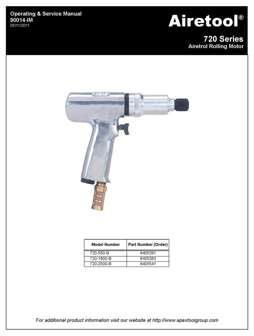
Airetool EIC-626-626 Instruction and safety manual

For additional product information visit our website at http://www.apextoolgroup.com
Operating & Service Manual
90103-IM
05/25/2011
EIC Series
Tube Cutters
Model # Order # Model # Order # Model # Order # Model # Order #
EIC-626-626 5515772 EIC-625-750 5515635 EIC-625-875 5523035 EIC-625-1000 5518583
Complete Cutter
5/8" OD
3/4" OD
7/8" OD
1" OD
Airetool®

Page - 2
Safety Recommendations
Someindividualsaresusceptibletodisordersofthehands
andarms whenexposed totasks whichinvolve highly
Tools with clutches can stall rather than shut-off if ad-
justed over the maximum power output of the tool, or if
there is a drop in air pressure. Operator must then resist
the stall torque until the throttle is released.
Higher torque Airetrols, inline and right angle, are sup-
plied with a torque reaction bar designed to work with the
torque of the tool it is specified for. These bars can be
bracedagainst thework orother suitablepoints toabsorb
andrelieve theoperator of thetorque reactiontransmitted
bythe tool.Toolbalance armsarealso availableto absorb
thetorquereactionof thetoolwhilebalancing the weightof
thetool for improvedergonomic applications.
Whenusing rightangleAiretrols withlever typethrottles,
besure thethrottle is positionedrelative tothe anglehead
so that the throttle will not become wedged against an
adjacentobjectin the “ON”positiondue to thetorquereac-
tion.The angle headmay berepositionedwith therespect
tothelever toaccommodate proper locationfor the task.If
tool is to be reversed, locate the throttle lever in a neutral
position that will prevent entrapment. Refer to operating
instructionsfor additional information.
Followgoodmachineshoppractices.Rotating shafts and
Hearing protectors are required in high noise areas, 85
dBaorgreater.Theoperationofothertoolsand equipment
in the area, reflective surfaces, process noises and reso-
nant structures, can substantially contribute to and in-
crease the noise level in the area. For additional informa-
tionon hearingprotection,refer toFederal OSHARegula-
tions, 29 Code of Federal Regulations Section 1910.95,
Occupational Noise Exposure, and American National
StandardInstitute, ANSIS12.6 HearingProtectors.
HEARING PROTECTION
EYE AND FACE PROTECTION
For additional information on eye and face protection,
refer to Federal OSHA Regulations, 29 Code of Federal
Regulations,Section1910.133 ,Eyeand Face Protection,
and American National Standards Institute, ANSI A87.1,
Occupational and Educational Eye and Face Protection.
Z87.1 is available from the American National Standards
Institute, Inc., 1430 Broadway, NewYork, NY 10018.
For your safety and the safety of others, read and un-
derstand the safety recommendations and operating in-
structionsbefore operatingthis tool.
ALWAYS WEAR PROTECTIVE EQUIP-
MENT
moving components can entangle and enwrap, and can
resultin serious injuries.Never wear longhair,loose fitting
clothes, gloves, ties or jewelry when working with or near
any power tool with an exposed rotating shaft or spindle.

Page - 3
Use of this tool may produce hazardous fumes, particles,
and/ordust.Toavoidadversehealtheffectsutilizeadequate
ventilationand/orarespirator.Readthematerialsafetydata
sheetof anymaterials involved inthe tubeexpansion pro-
cess.
Safety Recommendations
ThisAiretool product isdesigned to operateon minimum
90 psig ( 6.2 bar ), maximum 125 psig ( 8.6 ) air pressure.
Ifthe tool isproperly sizedandapplied, higherairpressure
isunnecessary.Excessiveairpressure increases theloads
and stresses on the tool parts, mandrels, rolls and cages
andmay resultin premature wearand orbreakage. Instal-
lation of a filter-regulator-lubricator in the air supply line
aheadof thetool isrequired.
Before the tool is connected to the air supply, check the
throttlefor properoperation (i.e., the throttle moves freely
and returns to the closed “OFF” position when released ).
Clear the air hose of accumulated dust and moisture. Be
carefulnotto endanger adjacentpersonnel.Before remov-
inga toolfromservice orchanging sockets,make sure the
air line is shut off and drained of air. This will prevent the
tool from operating if the throttle is accidently engaged.
NOTE : ANY USE OF THIS TOOL OTHER THAN IT’S
INTENDED PURPOSE COULD CAUSE MAJOR DAM-
AGE TO THE TOOL AS WELL AS POSE A RISK TO
THEOPERATOR.
repetitivemotionsand/orvibrations. Those individualspre-
disposed to vasculatory or circulatory problems may be
particularly susceptible.Cumulativetraumadisorderssuch
as carpal tunnel syndrome and tendonitis can be caused
oraggravatedbyrepetitious,forcefulexertionsofthehands
andarms.These disorders developgraduallyoverperiods
of weeks, months, and years.
TASKSSHOULDBEPERFORMEDINSUCHAMANNER
THAT THE WRISTS ARE MAINTAINED IN ANEUTRAL
POSITIONWHICHISNOTFLEXED,HYPEREXTENDED,
OR TURNED SIDE TO SIDE.
STRESSFUL POSTURES SHOULD BEAVOIDED AND
CAN BE CONTROLLED THROUGH TOOL SELECTION
ANDWORK LOCATION.
Any user sufferingfrom prolongedsymptoms oftingling,
numbness, blanching of the fingers, clumsiness or weak-
enedgrip,nocturnal pain inthehand, or anyotherdisorder
ofthe shoulders, arms,wrists, orfingersis advisedto con-
sultwith aphysician. Ifit isdetermined thatthe symptoms
arejobrelated oraggravatedby movementsandpostures
dictated by the job design, it may be necessary for the
employertotakestepstopreventfurtheroccurrences.These
steps might include, but are not limited to, repositioning
theworkpiece orredesigningtheworkstation, reassigning
workers to other jobs, rotating jobs, altering work pace,
and/or changing the type of tool used so as to minimize
stressonthe operator. Sometasksmayrequiremore than
one type of tool to obtain the optimum operator/tool/task
relationship.
The followingrecommendationswill helpreduceor mod-
eratethe effectsof repetitivework motions :
• Use a minimum hand grip force consistent with
propercontroland safeoperation.
• Keep wrists as straight as possible.
• Keepbody andhands warmand dry.
It is essential for safe operation that any operator of an
Airetrolusegoodbalance,surefooting,and proper posture
in anticipation of a torque reaction. Ensure that the
operator’s hands will not be wedged or pinched between
thework andthe toolwhen operating.
• Avoidanything thatinhibits blood
circulation
- Smoking tobacco
-Coldtemperatures
-Certain drugs
• Avoidhighlyrepetitive movementsofthe
handsand wrists,and continuous vibration
exposure.

Page - 4
To start, check the following list to make sure you
have selected the proper tools and that they are properly
set up for your application.
A. Check that you have selected the proper size
tubecutter andthat youhave installed the proper
pilot to fit the tube gage to be cut.
B. Check that you have the proper R.P.M. motor.
Seecutting speedselection guide on page X of
this manual. Be sure that the dead handle is ins
talledwrench tight. Haveassistant to hold dead
handleduringoperation.
C. Check that proper tool bits are installed in the
tubecutter.Three typesof bitsareavailable, non
ferrous,ferrous andstainless.
D. Check that the depth of cut is proper for the
application. Make sure that the thrust collar is
so that the bits will cut BEHIND the tube sheet.
E.Havea container ofanygoodcutting oilanddip
cutter bits into it after every two or three tubes,
dependingontube material.
F. Havea containerof solventforwashing orflush
ingthe chipsout ofthe cutterbit areaof thecutter
afterevery few cuts.
CUTTINGTHETUBES
Now you are ready to cut the first tube. Dip the cutter
bodyand bitsinto the cutting oil. Makesure thecutter bits
arein theretracted positionand insertthe cutterbody into
the tube to be cut. Insert until the taper of the thrust collar
is against the end of the tube, centering the cutter in the
tube I. D. Start the motor, air or electric. Place forward
pressure on the operating lever to feed the cutter bits into
thetube I.D. NOTE : “PIC” TYPE CUTTER, PUSH FOR-
WARDONTHEMOTOR. Alightbutsteadypressureshould
beapplied to theoperating leverduringthe cut.As the bits
start to break thru the O. D. of the tube CAUTION should
be taken to lighten the pressure on the operating lever to
preventthecutterbitsfromgrabbingcausingthemtobreak.
After the tube is cut off, make sure that the cutter bits are
intheclosedorretracted position beforeremovingthetube
cutterfromthe tube.Dipthe cutterbitsinto thesolventand
flush chips out of the cutter as needed. Repeat the above
steps and cut the remainder of the tubes to be cut.
We recommend that a cutting oil be used by either dip-
ping the cutter bits into it or by inserting some of the oil
into the ends of the tubes. We also recommend that the
cutterbe submergedinto asolvent andcutting oilsolution
to clean the chips out of the cutter. Dip the cutter bits into
thesolutionwhilemovingtheoperatingleverbackandforth.
FREQUENTLY inspect the cutter bits for sharpness, re-
placing if dull. See replacing the tool bits page 13. Proper
tool bit care is very important in operating your Airetool
tubecutter.NOTE :Toolbitscanbe sharpenedif removed
fromthe cutterbefore theyget tohot from dulling and turn
blue. See sharpening the bits on page 14.
The above instructions apply to all standard and extra
reach Airetool tube cutters models “EIC”, “PIC” and “TIC.
Please feel free to call the Airetool Customer Service or
any of the Airetool Branch Offices listed in this manual
shouldyouhaveanyquestionsorspecialapplicationsarise.
OPERATING INSTRUCTIONS
MODELS “EIC”, “PIC” & “TIC” TUBE CUTTERS

Page - 5
ITEM # PART # DESCRIPTION QUAN. ITEM # DESCRIPTION QUAN.
17 2675000 TTC-46-16-17 PILOT 117 TTC-6-14 PILOT 1
17 2675100 TTC-46-18 PILOT 117 TTC-6-15 PILOT 1
17 2675200 TTC-46-19 PILOT 117 TTC-6-16 PILOT 1
17 2675300 TTC-46-20 PILOT 117 TTC-6-17 PILOT 1
18 5338869 TTC-43 BIT SET (NON-FERROUS) 317 TTC-6-18 PILOT 1
18 5338870 TTC-43-S TOOL BIT SET (STEEL) 317 TTC-6-19 PILOT 1
18 5518303 TTC-43-SS BIT SET (STAINLESS) 317 TTC-6-20 PILOT 1
19 2979724 IC-44-T MANDREL TIP 118 TTC-3 BIT SET (NON-FERROUS) 3
20 2979725 IC-41 BODY TIP 118 TTC-3-S TOOL BIT SET (STEEL) 3
21 2979688 IC-41-X BODY EXTENSION 118 TTC-3-SS BIT SET (STAINLESS) 3
22 2675400 TTC-47 THRUST BODY 119 IC-4-T MANDREL TIP 1
23 2670000 TTC-9 BEARING 120 IC-1 BODY TIP 1
24 2670100 TTC-10 THRUST SPRING 121 IC-1-X BODY EXTENSION 1
25 2675700 TTC-48 THRUST NUT 122 TTC-7 THRUST BODY 1
26 2979676 IC-4-X MANDREL EXTENSION 123 TTC-9 BEARING 1
27 8000800 10-32 x 1/4" SOC SET SCREW 124 TTC-10 THRUST SPRING 1
NA 3240200 1100-019 WRENCH 3/16" 125 TTC-8 THRUST NUT 1
NA 3240275 1100-021 WRENCH 7/32" 126 IC-4-X MANDREL EXTENSION 1
NA 3240700 1100-038 WRENCH 3/8" 127 10-32 x 1/4" SOC SET SCREW 1
NA 3241200 1100-069 WRENCH 11/16" 1NA 1100-021 WRENCH 7/32" 1
NA 1100-044 WRENCH 7/16" 1
NA 1100-050 WRENCH 1/2" 1
NA 1100-069 WRENCH 11/16" 1
TUBE CUTTER BODY COMPLETE
PARTS LISTING FOR MODEL " EIC " & "TIC"
MODEL IC-625 ( 5/8" O.D. ) ( 5515574 )
MODEL IC-750 ( 3/4" O.D. ) ( 5515560 )
CUTTER BODY COMPLETE
FOR MODEL “EIC” & “TIC” TUBE CUTTERS

Page - 6
ITEM # PART # DESCRIPTION QUAN. ITEM # PART # DESCRIPTION QUAN.
17 2672500 TTC-36-12 PILOT 1
17 2676400 TTC-56-15 PILOT 1 17 2672600 TTC-36-13 PILOT 1
17 2990534 TTC-56-16 PILOT 1 17 2672700 TTC-36-14 PILOT 1
17 2990535 TTC-56-17 PILOT 1 17 2672800 TTC-36-15 PILOT 1
17 2676500 TTC-56-18 PILOT 1 17 2672900 TTC-36-16 PILOT 1
17 2676600 TTC-56-19 PILOT 1 17 2673000 TTC-36-17 PILOT 1
17 2676700 TTC-56-20 PILOT 1 17 2673100 TTC-36-18 PILOT 1
18 5338871 TTC-53 BIT SET (NON-FERROUS) 3 17 2673200 TTC-36-19 PILOT 1
18 5338872 TTC-53-S TOOL BIT SET (STEEL) 3 17 2673300 TTC-36-20 PILOT 1
18 5517757 TTC-53-SS BIT SET (STAINLESS) 3 18 5338867 TTC-33 BIT SET (NON-FERROUS) 3
19 2979409 IC-34-T MANDREL TIP 1 18 5338868 TTC-33-S TOOL BIT SET (STEEL) 3
20 2979726 IC-51 BODY TIP 1 18 5516337 TTC-33-SS BIT SET (STAINLESS) 3
21 2979692 IC-51-X BODY EXTENSION 1 19 2979409 IC-34-T MANDREL TIP 1
22 2676800 TTC-57 THRUST BODY 1 20 2979419 IC-31 BODY TIP 1
23 2673800 TTC-39 BEARING 1 21 2979680 IC-31-X BODY EXTENSION 1
24 2673900 TTC-40 THRUST SPRING 1 22 2673400 TTC-37 THRUST BODY 1
25 2677100 TTC-58 THRUST NUT 1 23 2673800 TTC-39 BEARING 1
26 2979684 IC-34-X MANDREL EXTENSION 1 24 2673900 TTC-40 THRUST SPRING 1
27 8000800 10-32 x 1/4" SOC SETSCREW 1 25 2673700 TTC-38 THRUST NUT 1
NA 3240650 1100-031 WRENCH 5/16" 1 26 2979684 IC-34-X MANDREL EXTENSION 1
NA 3241100 1100-063 WRENCH 5/8" 2 27 8000800 10-32 x 1/4" SOC SET SCREW 1
NA 3241200 1100-069 WRENCH 11/16" 1 NA 3240650 1100-031 WRENCH 5/16" 1
NA 3241100 1100-063 WRENCH 5/8" 2
NA 3241200 1100-069 WRENCH 11/16" 1
MODEL IC-875 ( 7/8" O.D. ) ( 5515581 ) MODEL IC-1000 ( 1" O.D. ) ( 5515571 )
PARTS LISTING FOR MODEL " EIC " & "TIC"
TUBE CUTTER BODY COMPLETE

Page - 7
LEVER HOUSING ASSEMBLY
FOR MODELS “EIC” & “TIC” TUBE CUTTERS
ITEM # PART # DESCRIPTION QUAN. ITEM # PART # DESCRIPTION QUAN.
1 2671300 TTC-21 LEVER HOUSING 1 9 8000800 10-32 x 1/4" SOC SET SCREW 4
2 2670200 TTC-11 SLEEVEBEARING 1 10 2670400 TTC-13 RADIAL BEARING SPRING 1
3 2671100 TTC-19 OPERATING LEVER GRIP 1 11 2670300 TTC-12 RADIAL BEARING 1
4 2670800 TTC-17-L OPERATING LEVER 1 12 2670600 TTC-15 LOCK NUT 1
5 2671000 TTC-18 OPERATING LEVER PIVOT 1 13 2670900 TTC-17-LS LEVER HANDLE STOP 1
6 8007300 10-32 x 7/8" SOC HD CAPSCREW 2 14 2670700 TTC-16 OPERATING COUPLING 1
7 8007400 10-32 HEX NUT 2 15 2979177 IC-4 MANDREL ADAPTER 1
8 2668800 TTC-5 PRESSURE SPRING 1 16 2975875 TTC-14-36 BODY EXT DRIVER 1
LEVER HOUSING ASSEMBLY
PARTS LISTING FOR MODEL TTC-21-A
5514403

Page - 8
TUBE CUTTER SIZE 5/8" O.D. 3/4" O.D. 7/8" O.D. 1" O.D.
BODY TIP IC-41 IC-1 IC-51 IC-31
2979725 2979306 2979726 2979419
BODY EXTENSION IC-41-X IC-1-X IC-51-X IC-31-X
2979688 2979672 2979692 2979680
MANDREL TIP IC-44-T IC-4-T IC-34-T IC-34-T
2979724 2979308 2979409 2979409
MANDREL EXTENSION IC-4-X IC-4-X IC-34-X IC-34-X
2979676 2979676 2979684 2979684
BODY EXTENSION DRIVER TTC-14-36 TTC-14-36 TTC-14-36 TTC-14-36
2975875 2975875 2975875 2975875
MANDREL ADAPTER IC-4 IC-4 IC-4 IC-4
2979177 2979177 2979177 2979177
MANDREL DRIVER ETC-30 ETC-30 ETC-30 ETC-30
3073240 3073240 3073240 3073240
PARTS NEEDED TO CONVERT TI NEW "IC" TYPE
AIRETOOL AIR DRIVEN
MODEL “TIC” INTERNAL TUBE CUTTER
NEW - MANDREL DRIVER - SAME ONE
FITS ALL SIZE “EIC” ELECTRIC CUTTERS
LEFT HAND THREAD
MANDREL DRIVER # ETC-30
( 3073240 )

Page - 9
SERVICE INSTRUCTIONS
MODELS “EIC”, “PIC” & “TIC” TUBE CUTTERS
MODELSELEC-1001-600 &ELEC-1201-350
ELECTRICTUBE CUTTER MOTORS
SERVICING THE AIRETOOL
ELECTRIC TUBE CUTTER MOTOR
TheAiretoolModels#ELEC-1001-600andELEC-1201-350
Electrictube cuttermotos rwill , whengiven propercare ,
give satisfactory operation for a very long period of time .
Periodical service should be done as per the following
recommendations.
MOTOR LUBRICATION
REPLACING THE CARBON BRUSHES
I
GEAR CASE LUBRICATION
REASSEMBLE
After careful inspection of parts for wear, they should be
thoroughlycleaned.Reassembleinreverseorder of disas-
sembly.

Page - 10
ELECTRIC TUBE CUTTER MOTOR
MODEL ELEC-1001-600 ( 3070050 )
( See parts List On Adjacent Page 13 )

Page - 11
ITEM # PART # DESCRIPTION QUAN. ITEM # PART # DESCRIPTION QUAN.
1 06-82-5316 PAN HD SCREW 2 30 22-64-3190 CORD SET 1
2 06-82-7270 PAN HD SCREW 5 32 28-28-0601 DIAPHRAGM 1
3 31-44-1651 RIGHT SIDE HANDLE 1 33 02-50-2440 NEEDLEBEARING 1
4 06-95-0075 TRUSS HD SCREW 2 34 32-75-1606 SPINDLEGEAR 1
5 22-22-1380 BRUSH HOLDER ASB. 1 35 34-60-1200 RETAINING RING 1
6 23-44-0190 BRUSHRET. CAP 2 36 02-50-1640 NEEDLEBEARING 1
7 23-52-0160 BRUSHSPRING 2 37 32-40-1251 INTERMEDIATEGEAR 1
8 22-16-0275 CARBON BRUSH 2 38 06-42-0800 WOODRUFF KEY 1
9 31-55-0190 COIL SHIELD 1 39 36-66-2012 INTERMEDIATESHAFT 1
10 31-12-0196 SWITCHCAP 1 40 02-04-0725 BALL BEARING 1
11 23-66-1868 REV. SWITCH ASBLY. 1 41 28-14-1921 GEAR CASE 1
12 06-95-5150 HEX HD SCREW 1 42 02-04-1536 BALL BEARING 1
13 06-81-1060 FIELD BOLT 2 43 34-80-2500 RETAINING RING 1
14 06-82-7270 PAN HD SCREW 1 44 06-82-5532 PAN HD SCREW 2
15 23-66-0167 ON-OFF SWITCH 1 45 06-82-5432 PAN HD SCREW 1
16 31-44-1656 LEFT HANDLE HALF 1 46 06-42-2000 WOODRUFF KEY 1
17 06-72-1720 NAMEPLATERIVIT 2 47 38-50-5475 SPINDLE 1
18 12-99-1750 SERVICENAMEPLATE 1 51 43-62-0875 SIDEHANDLE 1
20 02-04-0845 BALL BEARING 1 52 14-46-1001 FOAMSLUG KIT (10) 1
21 06-57-2975 HEX NUT 2
22 23-16-0456 FIELD INSULATOR 1 NS 49-08-0800 TYPE"A" GREASE 1
23 18-31-0200 FIELD ASBLY 120V 1
24 28-50-6220 MOTOR HOUSING 1
25 31-05-0050 BAFFLE 1
26 16-30-0326 ARMATURE120 VOLT 1
27 22-84-0531 FAN ASSEMBLY 1
28 02-04-0911 BALL BEARING 1
29 44-76-0210 CORD PROTECTOR 1
ELECTRIC TUBE CUTTER MOTOR
PARTS LISTING FOR MODEL ELEC-1001-600
3070050

Page - 12
TOOL BIT REPLACEMENT INSTRUCTIONS
FOR AIRETOOL TUBE CUTTER MODELS: EIC, PIC & TIC
NOTE : THESE INSTRUCTIONS PERFORMED WITH ASSEMBLY
“BB” ATTACHED TO THE LEVER HOUSING (MODELS EIC & TIC)
OR SPRING HOUSING (MODEL PIC).
1.REMOVEASSEMBLY“AA” BYTURNING THECUTTER
BODY COUNTERCLOCKWISETHEN TURN THE
MANDREL TIPCOUNTERCLOCKWISE.
2.REMOVETHE PILOT(TURNCOUNTERCLOCKWISE)
AND REPLACE TOOL BITS.
3. REPLACEPILOT ONTHE
CUTTER BODY.
4. MOVETHEMANDRELEXTENSION FORWARD BY
PUSHING FORWARD ONTHE(LEVER ONEIC&TIC)
(MANDREL DRIVER ONPIC).
5.THREADTHEMANDRELTIPINTOTHE MANDREL
EXTENSIONANDTHE CUTTERBODY INTOTHE CUTTER
BODYEXTENSIONCLOCKWISEUNTILSNUG.(IF
MANDRELEXTENSION UNTHREADSAT LEVER
OR MANDRELDRIVER,SIMPLYTHREAD
THISMANDRELASSEMBLYINTOTHE
LEVEROR MANDREL DRIVER).

Page - 13
POINTS FOR GOOD TUBE CUTTING
1. KEEP BITS COOL - This will extend the bits life. It possible, use a flushing system of air and some type of good
cuttingfluid.
2. DO NOT FORCE FEED - To much pressure of the tool bits can cause the bits to puncture thru the tube wall which
may cause the bits to break.
3. KEEP BIT AND MANDREL AREA CLEAN OF CHIPS - Cleaning of the chips from the area of the tool bits
andmandrel willallowfor freemovement ofboth. Chips inthis areacan causethe mandrel andor toolbits to bindand break.
4. SHARPEN TOOL BITS - Sharpentool bits,per abovespecifications, beforethey are allowed to wearand overheat.
Overheating will remove thetemper from thetool bit sothat sharpening willnot last verylong. KEEP BITS COOL !
5. TOOL BIT SELECTION - Feed angels of the tool bit are very important for the type of material that is being cut. Be
sure that you are using the proper tool bits!
6. PROPER CUTTING SPEED -Thisis veryimportantfor proper cuttingand fortool bitlife. See R.P.M. recommenda-
tions on page 18 in this manual.

Page - 14
RECOMMENDED CUTTING SPEEDS
FOR AIRETOOL TUBE CUTTERS MODELS “EIC”, “PIC” &
“TIC”
TUBE
MATERIAL 1/4" 3/8" 1/2" 5/8" 3/4" 7/8" 1" 1 1/4" 1 1/2" 2"
ALUMINUM 7500 5000 3800 3000 2500 2200 1900 1500 1275 950
( 500 FPM ) rpm. rpm. rpm. rpm. rpm. rpm. rpm. rpm. rpm. rpm.
BRASS 4600 3050 2300 1825 1525 1300 1150 925 750 575
( 300 FPM ) rpm. rpm. rpm. rpm. rpm. rpm. rpm. rpm. rpm. rpm.
COPPER 3825 2550 1900 1525 1275 1100 950 750 625 500
( 250 FPM ) rpm. rpm. rpm. rpm. rpm. rpm. rpm. rpm. rpm. rpm.
CARBON STEEL 2150 1425 1075 850 700 625 525 425 350 275
( 140 FPM ) rpm. rpm. rpm. rpm. rpm. rpm. rpm. rpm. rpm. rpm.
STAINLESS STEEL 1000 660 500 400 330 285 250 200 165 125
( 65 FPM ) rpm. rpm. rpm. rpm. rpm. rpm. rpm. rpm. rpm. rpm.
TITANIUM 450 300 230 185 155 130 115 95 75 60
( 30 FPM ) rpm. rpm. rpm. rpm. rpm. rpm. rpm. rpm. rpm. rpm.
INCONEL 305 205 155 125 100 90 75 60 50 40
( 20 FPM ) rpm. rpm. rpm. rpm. rpm. rpm. rpm. rpm. rpm. rpm.
NOTE : The recommended cutting speeds above are based on published speeds and feeds. A slower rpm may be
necessary depending on tube material analysis and hardness. Proper lubrication must be used.
T U B E O. D.


Sales & Service Centers
Note: All locations may not service all products. Please contact the nearest Sales & Service Center for
the appropriate facility to handle your service requirements.
Dallas, TX Detroit, MI Houston, TX Lexington, SC
Apex Tool Group Apex Tool Group Apex Tool Group Apex Tool Group
Sales & Service Center Sales & Service Center Sales & Service Center 670 Industrial Drive
1470 Post & Paddock 2630 Superior Court 6550 West Sam Houston Lexington, SC 29072
Grand Prairie, TX 75050 Auburn Hills, MI 48326 Parkway North, Suite 200 Tel: 800-845-5629
Tel: 972-641-9563 Tel: 248-391-3700 Houston, TX 77041 Tel: 803-951-7544
Fax: 972-641-9674 Fax: 248-391-7824 Tel: 713-849-2364 Fax: 803-358-7681
Fax: 713-849-2047
Los Angeles, CA Seattle, WA York, PA Canada
Apex Tool Group Apex Tool Group Apex Tool Group Apex Tool Group
Sales & Service Center Sales & Service Center Sales & Service Center Sales & Service Center
15503 Blackburn Avenue 2865 152nd Avenue N.E. 3990 East Market Street 5925 McLaughlin Road
Norwalk, CA 90650 Redmond, WA 98052 York, PA 17402 Mississauga, Ont. L5R 1B8
Tel: 562-623-4457 Tel: 425-497-0476 Tel: 717-755-2933 Canada
Fax: 562-802-1718 Fax: 425-497-0496 Fax: 717-757-5063 Tel: 905-501-4785
Fax: 905-501-4786
Germany England France China
Cooper Power Tools Cooper Power Tools Cooper Power Tools SAS Cooper (China) Co., Ltd.
GmbH & Co. OHG GmbH & Co. OHG a company of a company of
a company of a company of Apex Tool Group, LLC Apex Tool Group, LLC
Apex Tool Group, LLC Apex Tool Group, LLC 25 rue Maurice Chevalier 955 Sheng Li Road,
Industriestraße 1 C/O Spline Gauges 77330 Ozoir-La-Ferrière Heqing Pudong, Shanghai
73463 Westhausen Piccadilly, Tamworth France China 201201
Germany Staffordshire B78 2ER Tel: +33 1 6443 2200 Tel: +86-21-28994176
Tel: +49 (0) 73 63 81 0 United Kingdom Fax: +33 1 6443 1717 Fax: +86-21-51118446
Fax: +49 (0) 73 63 81 222 Tel: +44 1827 8741 28
Fax: +44 1827 8741 28
Mexico Brazil Hungary
Cooper Tools Cooper Tools Industrial Ltda. Cooper Tools Hungaria Kft.
de México S.A. de C.V. a company of a company of
a company of Apex Tool Group, LLC Apex Tool Group, LLC
Apex Tool Group, LLC Av. Liberdade, 4055 Berkenyefa sor 7
Vialidad El Pueblito #103 Zona Industrial - Iporanga Pf: 640
Parque Industrial Querétaro 18087-170 Sorocaba 9027 Györ
Querétaro, QRO 76220 SP Brazil Hungary
Mexico Tel: +55 15 2383929 Tel: +36 96 66 1383
Tel: +52 (442) 211-3800 Fax: +55 15 2383260 Fax: +36 96 66 1135
Fax: +52 (442) 103-0443
90103-IM/Printed in USA 05/2011/Copyright © Apex Tool Group, LLC
Apex Tool Group, LLC
1000 Lufkin Road
Apex, NC 27539
Phone: 919-387-0099
Fax: 919-387-2614
www.apextoolgroup.com
Airetool®
This manual suits for next models
3
Table of contents
Other Airetool Power Tools manuals
