Silca Crown D422143XA User manual

®
Operating manual
D422143XA
vers.
1.0
CROWN
CROWN

© 2001 SILCA S.p.A - Vittorio Veneto
This manual has been drawn up by SILCA S.p.A.
All rights reserved. No part of this publication may be reproduced or used in any form or by any means (photocopying,
microfilm or other) without the written permission of SILCA S.p.A.
published in october 2001
Printed in Vittorio Veneto
by SILCA S.p.A.
via Podgora, 20 (Z.I.)
31029 VITTORIO VENETO (TV) - Italy

INDEX
1
TRANSPORT ..............................................................................................................3
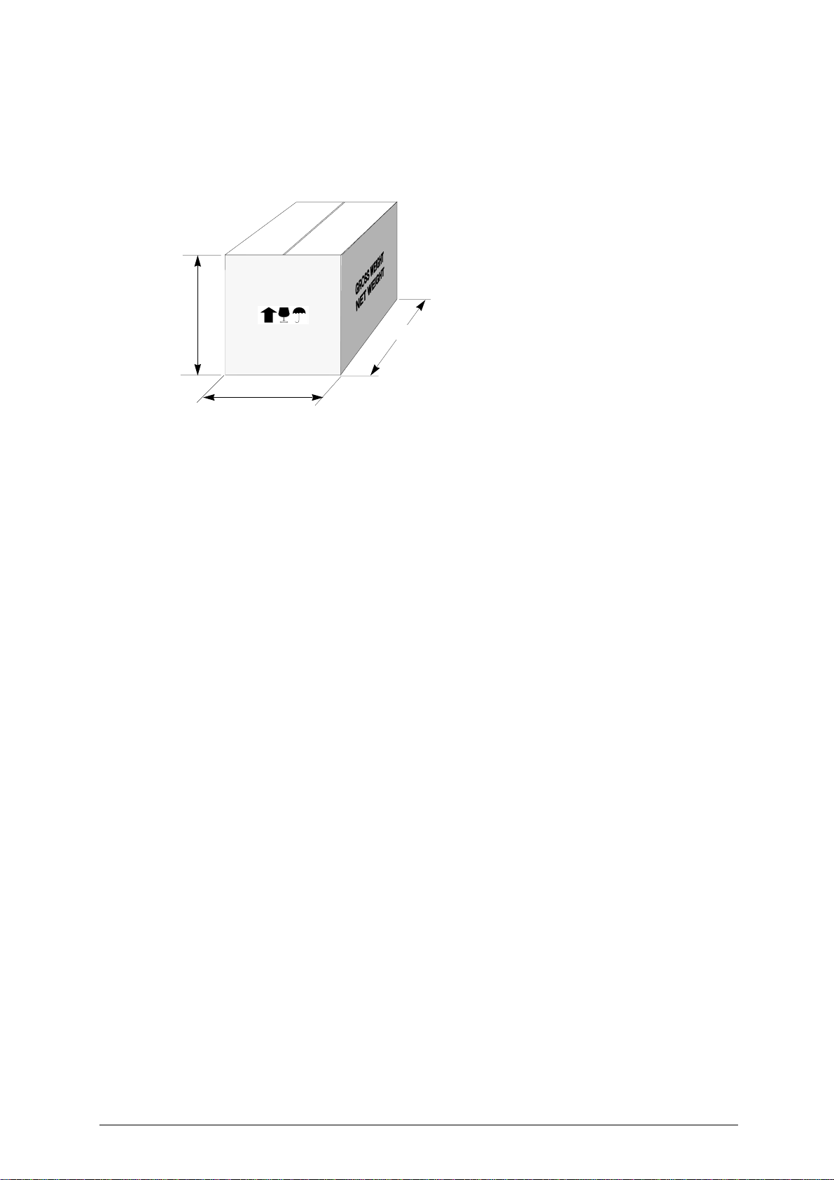
1.1 Packing ............................................................................................................3
1.2 Transport .........................................................................................................3
1.3 Unpacking ........................................................................................................3
1.4 Machine handling .............................................................................................3
2
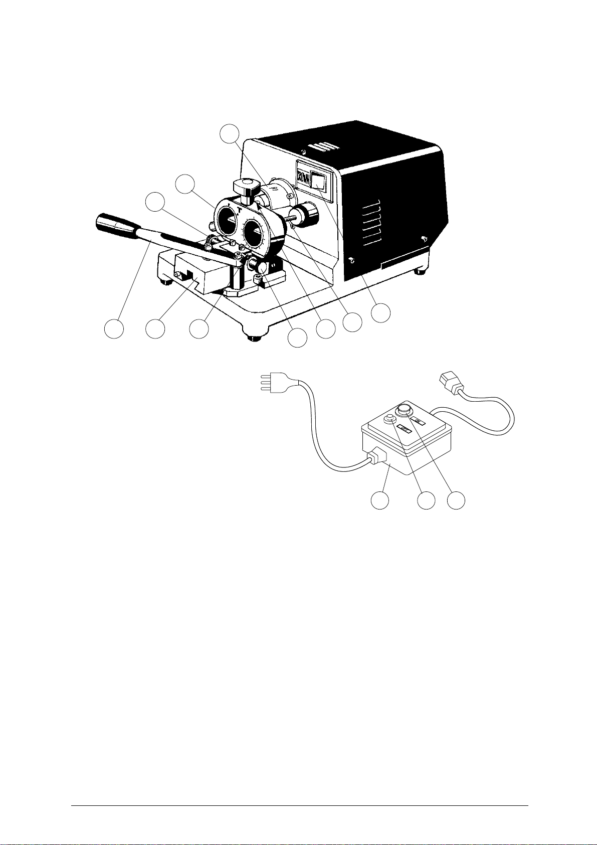
WORKING PARTS .....................................................................................................4
3
MACHINE DESCRIPTION ..........................................................................................5
3.1 Technical data .................................................................................................6
3.2 Electrical circuit ................................................................................................6
4
ACCESSORIES PROVIDED ......................................................................................7
5
MACHINE INSTALLATION AND PREPARATION ....................................................8
5.1 Checking for damage .......................................................................................8
5.2 Environmental conditions .................................................................................8
5.3 Positioning .......................................................................................................8
5.4 Description of work station ...............................................................................9
5.5 Separate parts .................................................................................................9
5.6 Connection to the mains ..................................................................................9
6
REGULATION AND USE OF THE MACHINE .........................................................10
6.1 Control and gauging ......................................................................................10
6.2 Gauging .........................................................................................................10
6.3 Cutting operations ..........................................................................................11
7
MAINTENANCE ........................................................................................................12
7.1 Cutter replacement ........................................................................................12
7.2 Tracer point replacement ...............................................................................12
7.3 Replacing the fuses .......................................................................................12
8
WASTE DISPOSAL ..................................................................................................13
9
ASSISTANCE ...........................................................................................................14
9.1 How to request service ..................................................................................14
10
SYNCHRONISED DEVICES ....................................................................................15
10.1 Devices T2 - T3 - T4 - T5 - T6 - T7 - T8 - T9 - T13 ........................................16
10.2 Self-Centering Device T10 .............................................................................17
10.3 Self-Centering Device T15 .............................................................................20
10.4 T14 synchronised device for cutting 5VP3 keys ............................................22
10.5 T17 Synchronised device ..............................................................................23


Operating manual - English CROWN
Copyright Silca 2001 1
GUIDE TO THE MANUAL
This manual has been produced to serve as a guide for users of the CROWN key-cutting machine. Read
it carefully; it is essential if you wish to operate your machine safely and efficiently.
C
ONSULTATION
The contents of the manual are divided into sections relating to: Chapter
- Transport and handling ................................................................................................................... 1
- Description of machine and safety devices .......................................................................... 2-3-4-5
- Proper use of the machine .......................................................................................................... 5-6
- Maintenance .................................................................................................................................. 7
- Optional devices ........................................................................................................................... 10

CROWN Operating manual - English
2 Copyright Silca 2001
GENERAL INSTRUCTIONS
The CROWN key-cutting machine has been designed according to the specifications of the Machine
Directives. From the design stage risks for the operator have been eliminated in all areas: transport,
regulation, cutting and maintenance.
The use of protective goggles is compulsory during cutting operations, as indicated on the machine
itself and in this manual.
The material used in the manufacture of this machine and the components employed during use of
the machine are not dangerous and their use complies with standards.
U
SE
The CROWN key-cutting machine must be installed and used in the way laid down by the manufacturer,
as illustrated in this manual.
If the machine is used differently or for purposes different from those described in this manual, the
customer will forego any rights he may have over SILCA S.p.A. Furthermore, unforeseen danger to the
operator or any third parties may arise from incorrect use of the machine.
Negligence in the use of the machine or failure on the part of the operator to observe the instructions
given in this manual are not covered by the guarantee and the manufacturer declines all responsibility
in such cases.
It is therefore indispensable to read the operating manual carefully in order to make the best use
of the CROWN key-cutting machine and benefit from its potential.
F
URTHER RISKS
There are no further risks arising from the use of the CROWN key-cutting machine.
P
ROTECTION AND SAFETY PRECAUTIONS FOR THE OPERATOR
The CROWN key-cutting machine is built entirely to standards. The operations for which it has been
designed are easily carried out at no risk to the operator.
The adoption of general safety precautions (use of protective goggles) and observation of the
instructions provided by the manufacturer in this manual eliminate all human error, unless deliberate.
The CROWN key-cutting machine is designed with features which make it completely safe in all its
parts.
• Power supply
The key-cutting machine must be supplied with electricity. The plug must be earthed.
• Start-up
The machine is started up:
- by means of the START button on the safety device (standard with 230V key-cutting machines, on
request for other voltages);
- by means of the master switch.
• Operation
The machine is started up by means of a motor switch.
• Maintenance
The operations to regulate, service, repair and clean the machine have been devised in the simplest
and safest way possible. There is no danger of removable parts being replaced wrongly or unsafely.
• machine identification
The CROWN is provided with an identification label which shows the serial number (fig. 1).
Fig. 1
N˚ MATRICOLA
SERIAL No.
Telefax (0438) 913800
Telex 410579 SILCA I
SILCA S.p.A. - Via Podgora 20 (Z.I.)
31029 VITTORIO VENETO (TV) ITALY
TIPO
TYPE
VOLT A.
Hz. WATT
(0438) 9136
☎
Manufacturer’s
identity
Serial No.
Type of machine
Absorbed power
Working
frequency Absorbed
current
Year of
manufacture
CE mark
Working
voltage
®

Operating manual - English CROWN
Copyright Silca 2001 3
1 TRANSPORT
The CROWN key-cutting machine is easily transported and is not dangerous to handle.
The packed machine can be carried by one person.
1.1 Packing
Fig. 2
1.2 Transport
It is advisable to use the packing every time the machine is transported, as this will avoid knocks which
could cause damage to the machine, persons or things.
1.3 Unpacking
To remove the machine from the packing box:
1) cut the straps with scissors and remove.
2) prise off the staples
3) open the box without damaging it as it may be used again (e.g. removals, dispatch to the manufac-
turers for repairs or servicing).
4) check the contents of the box, which should comprise:
- 1 CROWN key-cutting machine
- 1 set of documents, including: operating manual, spare parts list and guarantee
- 1 set of accessories
- 1 power cable
1.4 Machine handling
When the CROWN key-cutting machine has been unpacked, place it directly on its workbench.
This operation can be carried out by one person, firmly holding the base, and no other part, to lift
and carry the machine.
530 mm
350 mm
350 mm

CROWN Operating manual - English
4 Copyright Silca 2001
2 WORKING PARTS
Fig. 3
A - Master switch
B - Tracer point
C - Cutter
D - Safety screen
E - Slide
F - Lever
G - Height adjusting screw
G1- Wedge locking knob
H - Wedge
L - Synchronised device (optional)
Q - Safety device
R - START button
S - STOP button
A
B
C
D
EF H
S RQ
L
G1
G

Operating manual - English CROWN
Copyright Silca 2001 5
3 MACHINE DESCRIPTION
The CROWN is a professional machine designed for cutting tubular keys. The main parts of the machine
are described below:
S
AFETY DEVICE
The device is connected to a power plug with a differential switch. It activates the key-cutting machine
when the illuminated START button (R) is pressed and cuts out when the STOP button (S) is pressed.
M
ASTER SWITCH
The master switch (A) with which to start the induction motor is situated on the front of the key-cutting
machine, on the right.
M
OTOR UNIT
The CROWN key-cutting machine has a direct drive motor. The shaft/cutter unit is protected by a cover
(D).
M
OBILE UNIT
The mobile unit comprises a slide (E) and an adjustable wedge (H).
The slide moves by lever (F) which returns to the idle position by means of a return spring located under
the slide.
The height of the wedge can be adjusted by means of a knob (G), which is also used to lock the wedge
in position.(G1)
K
EY
-
CUTTING UNIT
The key-cutting unit comprises the operational parts of the machine, which work together to read and
reproduce the key.
• Cutter
A cutter with cylindrical hold (C) is the part of the key-cutting machine used to cut the key blank. It is
made of super rapid steel and has four cutting edges.
• Tracer point
The tracer point (B) is used for reading the original key and is located on the right-hand side of the
machine.
• Device
The device installed, in this case a T10, is used to seat the key to be copied on the right and the key
blank to be cut on the left.
Devices may vary according to the type of key to be cut. Their names, installation and operation are
described in this manual (see cap.10 a pag.15).

CROWN Operating manual - English
6 Copyright Silca 2001
3.1 Technical data
MOTOR: One-speed single phase;
Volt:220, Hertz:50, Kw:0.15, rpm:2800
CUTTING TOOL: Super rapid steel HSS
MOVEMENTS: manual on guide
DIMENSIONS: width: 230 mm depth: 450 mm height: 180 mm
WEIGHT: Kg. 15,5
SOUND PRESSURE: sound pressure Lp(A) max. 75,76 dB(A)
3.2 Electrical circuit
The main parts of the electrical and electronic circuit on the CROWN are listed below:
1) Safety device intake
2) START button
3) Relay 3 contacts 220V
4) STOP button
5) Relay contacts
6) Safety device plug
7) Machine plug
8) Fuse rapid 5x20 3,15A - 250V
9) Master switch
10)Motor 230Va.c. 50Hz
11)Condenser 6,3 µF
5
1
2
3
4
6
safety device
7
88
9
10
11

Operating manual - English CROWN
Copyright Silca 2001 7
4 ACCESSORIES PROVIDED
A set of accessories is supplied for use with the machine or for servicing (tools, Allen keys and
adapters).
The accessories provided are:
cod. D302883ZZ
8 mm SPANNER
cod. D309226ZZ
FUSE 5X20 (2 pz)
3,15 Amp fuse-rapid (230V)
1
2
3
4
5
6
9
10
cod. D300221ZZ
2 mm ALLEN KEY 2 mm
cod. D300222ZZ
2,5 mm ALLEN KEY
cod. D300225ZZ
5 mm ALLEN KEY
cod. D300226ZZ
6 mm ALLEN KEY
cod. D300219ZZ
3 mm ALLEN KEY
cod. D300223ZZ
3 mm ALLEN KEY
cod. D300224ZZ
4 mm ALLEN KEY
8
cod. D302434ZZ
1,5 mm ALLEN KEY
7

CROWN Operating manual - English
8 Copyright Silca 2001
5 MACHINE INSTALLATION AND PREPARATION
The key-cutting machine can be installed by the purchaser and does not require any special skills.
However, some checks and preparation for use need to be carried out by the operator.
5.1 Checking for damage
The CROWN key-cutting machine is solid and compact and will not normally damage if transport,
unpacking and installation have all been carried out according to the instructions in this manual.
However, it is always advisable to check that the machine has not suffered any damage.
5.2 Environmental conditions
To ensure that the best use is made of the CROWN key-cutting machine, certain parameters must be
borne in mind:
- damp, badly ventilated sites should be avoided.
- the ideal conditions for the machine are:
- temperature: between 0 and 40˚C
- relative humidity: approx 60%
5.3 Positioning
Place the machine on a horizontal surface, solid enough to take the weight (16 Kg).
To facilitate operation and maintenance, install the machine with a clearance of at least 200 mm on all
sides (fig. 4).
Check that the weight of the machine is evenly distributed over the four feet; horizontal positioning
prevents vibrations during operation.
WARNING: ensure that the machine voltage is the same as that of the mains, which must be properly
earthed and provided with a differential switch.
Fig. 4
200 mm
200 mm
200 mm

Operating manual - English CROWN
Copyright Silca 2001 9
5.4 Description of work station
The machine needs only one operator, who has the following controls at his/her disposal (fig. 5):
• safety device (Q).
• master switch (A).
• carriage lever handle(F).
Fig. 5
5.5 Separate parts
The detachable parts of the machine are packed separately and must be fitted to the CROWN by the
operator, as follows:
P
OWER CABLE
First connect the key-cutting machine and the power cable (Q) then connect the free end of the power
cable to the power mains (fig. 6).
Fig. 6
5.6 Connection to the mains
It is extremely important for the operator’s safety to ensure that the key-cutting machine is connected to
the power mains with the right voltage and by means of a properly earthed differential switch.
A
Q
F
power cable
power
mains
Q

CROWN Operating manual - English
10 Copyright Silca 2001
6 REGULATION AND USE OF THE MACHINE
6.1 Control and gauging
The cutter on the CROWN key-cutting machine requires periodic replacement when it is too worn to cut
properly.
Every time the cutter is replaced, it must be gauged.
6.2 Gauging
• Gauging the cutter
Gauging consists of aligning the machine cutter with its tracer point. To do so, proceed as follows:
1) detach the power supply cable from the machine socket.
2) fit the new cutter, but do not lock in with the grub screw (C1) (fig. 7).
3) fit two key blanks into the device and secure in place.
4) take the slide forward so that the tracer point comes into contact with the key. In this position use
the grub screw to lock the cutter butting against the key (fig. 7).
• Gauging height
The height of the wedge is adjusted solely by means of the self-centring devices, the instructions for the
use of which are included in this manual (see ch.10, page 15.).
Using the standard synchronised devices the position of the wedge should be on 0.
Fig. 7
C1

Operating manual - English CROWN
Copyright Silca 2001 11
6.3 Cutting operations
WARNING: To work in complete safety, pay special attention to the following recommendations:
• Always work with dry hands.
• Check that the machine is properly earthed.
• Use the protective goggles, even if the cutting tool is fitted with a protective shield.
• Start the motor only when all the operations with the carriage have been carried out
(securing keys, etc.).
• Keep hands away from the cutting tool when in motion.

CROWN Operating manual - English
12 Copyright Silca 2001
7 MAINTENANCE
WARNING: for repairs or replacement of parts for maintenance, the ‘CE’ mark is guaranteed only if original
spare parts provided by the manufacturer are used.
Although the CROWN key-cutting machine does not require special maintenance, it is advisable to
check and, if necessary, replace the parts subject to wear (cutting tool, tracer point).
Replacement is simple and can be carried out by the operator.
CLEANING: it is advisable to use a soft brush to keep the carriage and clamps free of chippings from
cutting operations.
WARNING: do not use compressed air!
WARNING: to keep the machine well maintained we recommend using protective oil, e.g. WD40 or similar,
applied to the burnished mechanical parts. This prevents oxidation of the parts in question
(clamps, guides, carriages, etc.).
Before starting any type of maintenance (checks or replacements), read the instructions below:
• never carry out maintenance or servicing with the machine switched on.
• always remove the mains plug.
• follow all the instructions in the manual to the letter.
• use original spare parts.
• always check that any screws or nuts removed when replacing a piece are properly
tightened.
7.1 Cutter replacement
To replace the cutter, loosen the grub screw (C1) and remove the cutter. Fit the new cutter and go on to
the gauging operation, (see ch.6.2, page 10.).
7.2 Tracer point replacement
To replace the tracer point, loosen the screw (B1) and unscrew the tracer point from its threaded seat.
Screw in the new tracer point, tighten the screw and go on to the cutter gauging operation (see ch.6.2,
page 10.).
Fig. 8
7.3 Replacing the fuses
WARNING: Unplug the machine from the mains.
1) Detach the wiring from the machine plug;
2) turn the key-cutting machine so that the fuse box is easily reached;
3) remove the fuse box placed below the power inlet (fig. 9);
4) replace the fuses;
5) close the fuse box and connect the power cable.
WARNING: the fuses must both be of the same type (rapid) and with the same amps (3,15A)
Fig. 9
C1 B1
fuse box
fuses

Operating manual - English CROWN
Copyright Silca 2001 13
8 WASTE DISPOSAL
EU regulations establish special arrangements for the disposal of waste (**).
W
ASTE DERIVING FROM CUTTING OPERATIONS
Although residue coming from the key-cutting operations is classified as special waste, it is included in
solid urban waste (SUW) as metal wool.
Such waste is sorted according to its classification under current Italian and EU law and consigned to
the proper disposal units.
Cases where waste can be considered contaminated or containing toxic/harmful substance sufficient
to transform it from SUW to toxic/harmful waste, are listed in the enclosures to current Italian and EU
waste disposal regulations.
Re-cycling is a recommended ecological practice.
P
ACKING
The CROWN is consigned in a cardboard packing box which can be re-used if undamaged. When it is
to be thrown away it is classified as solid urban waste and should be placed in the special paper
collecting bins
To facilitate disposal of the waste generated by the machine during its operation and of the ma-
chine itself at the end of its useful life, refer to identification of the main types of waste by the
relative European CER code:
code CER
- Iron filings and swarf 12 01 01
- Paper and cardboard packaging 15 01 01
- Plastic packaging 15 01 02
(**)
"Waste" is any substance or object deriving from human activity or natural cycles, thrown away or to be thrown
away
.

CROWN Operating manual - English
14 Copyright Silca 2001
9 ASSISTANCE
Silca provides full assistance to purchasers of the CROWN key-cutting machine.
To ensure complete safety for the operator, any job not specified in this manual should be carried out
by the manufacturer or in the special Service Centres recommended by Silca.
On the back cover of this manual is a list of the manufacturer’s addresses; listed below are the
addresses of specialised Service Centres.
9.1 How to request service
The guarantee attached to CROWN key-cutting machine ensures free repairs or replacements of faulty
parts within 12 months of purchase. All other service calls must be arranged by the customer with Silca
or with a Silca Service Centre

Operating manual - English CROWN
Copyright Silca 2001 15
10 SYNCHRONISED DEVICES
There are various types of tubular keys and for this reason there are various synchronised devices to
use according to the function of the key to be cut.
To find a device suitable for the key to be cut, consult the table below:
SYNCHRONISED DEVICES
T2
D700189ZB
for:
PROGRES-FONTAINE
CORNI
(5)
T8
D700195ZB
for:
POLLUX
(5)
T3
D700190ZB
for:
PROGRES-FONTAINE
CORNI
(7)
T9
D700196ZB
for:
POLLUX
(7)
T4
F700191ZB
for:
VIGIE-PICARD
(6)
T13
D700199ZB
for:
CAVITH
T5
D700192ZB
for:
LAPERCHE
(6)
T14
D704534ZB
for:
VIGIE-PICARD
(8)
T6
D700193ZB
for:
JPM
(5)
T17
D709355ZB
for:
GB2
T7
D700194ZB
for:
DAD-DECAYEUX
(5)
T10
D700329ZB
for:
tubolar keys
ø universal
mm 9,2 ... mm10,2
T15
D705355ZB
for:
tubular keys
ø universal
mm 6 ... mm12,5

CROWN Operating manual - English
16 Copyright Silca 2001
10.1 Devices T2 - T3 - T4 - T5 - T6 - T7 - T8 - T9 - T13
Instructions for the assembly and use of the above-mentioned devices are given below:
1) Fit the chosen device on the CROWN key-cutting machine and lock in place by means of the knob
(M) (fig. 10).
2) Place the key to be copied into the right-hand side of the device and the key to be cut in the left-
hand side (there is only one possible position dictated by the shape of the key) and push in all the
way up to the front stop (N). Lock in place with the grub screws (T) and (T1), which are visible
through the holes on top of the device. If they are not visible, turn the key clockwise until the grub
screws can be seen.
3) Block rotation of the device with the knob (K) and turn on the machine motor to start cutting.
4) Push the carriage lever forwards so that the tracer point can enter the cut to be copied. Take great
care when carrying out this operation.
5) Take the carriage back to the idle position, release rotation by means of the knob (K) and turn the
key clockwise until it reaches the next notch, block the knob (K) and make the second cut.
6) Repeat the operation above until all the cuts have been made.
Fig. 10
Fig. 11
M
NT1 T
K
Table of contents
Other Silca Power Tools manuals