Airfield Audio Liminator 2 User manual

LIMINATOR 2
CLASS A DUAL TRANSFORMER STEREO COMPRESSOR
OWNER’S MANUAL
www.airfieldaudio.com

TABLE OF CONTENTS
SECTION PAGE
INTRODUCTION 2
INSTALLATION 3
FRONT PANEL CONTROLS 4
OPERATION 5
SPECIFICATIONS 7
WARRANTY AND REGISTRATION 8
- 1 -
www.airfieldaudio.com

INTRODUCTION
Thank you for choosing Airfield Audio.
Our many years of specializing in tech service, custom build and modifications to high
end studio and professional audio installations are now being expanded with an exciting
new product line. For the Airfield Audio Liminator 2 we have analyzed more than a
dozen classic and vintage audio compressors, and have distilled the best of the best into
this device. Your ears will love the sound of this unique analog processor.
Class A discrete transistor circuitry is used exclusively, with classic input and output
transformers deployed as an important element of the design. In fact, a main feature of
the Liminator 2 is the inclusion of 2 switchable input transformers per channel for a great
range of flexibility and tone. In addition, dual power supplies are incorporated for
absolute minimum crosstalk and maximum stereo separation. All front panel controls as
well as internal components have been selected for ruggedness and long life. We take
pride in quality construction; all units are handcrafted with care, thoroughly bench tested,
calibrated and burned in for 48 hours.
The Airfield Audio Liminator 2 exemplifies state of the art analog audio design, and
delivers natural, musical characteristics to the recording process. One of the most
versatile compressors ever invented, it can be used with confidence on voice, all
instruments, any sound source, stereo or multi-channel mix and mastering.
For reasons not even science can fully explain, the best analog devices create a sonic
magic that flows from the sound source through real parts and circuitry into the human
ear with the highest clarity and resolution. Airfield Audio is dedicated to this natural
process. It sounds very very very very good.
- 2 -
www.airfieldaudio.com

INSTALLATION
- 3 -
5 1 2 6 4 3
REAR PANEL VIEW
1. IMPORTANT :SET THE MAINS SWITCH ON THE REAR PANEL TO THE
CORRECT VOLTAGE.
2. Be certain that the unit has a ½ AMP fuse (115 VAC mains)
or ¼ AMP fuse (230 VAC mains).
3. Connect line level audio input cables from your source (microphone preamp, EQ,
analog console or DAW outputs) to the 3 pin XLR female connectors. The input
XLR connectors are Balanced Transformer Coupled, pin 2 hot.
4. Connect audio output cables to the 3 pin XLR male connectors and plug them into
your recording/mixing device. The output XLR’s are Balanced Transformer
Coupled, pin 2 hot.
5. Connect the supplied IEC power cable to the IEC mains socket on the rear panel.
USE ONLY A 3 PRONG GROUNDED POWER CABLE. For safety reasons do
not lift the ground on the power plug by using a 3 to 2 ground lift adapter.
6. Link Jack: connect a standard ¼” unbalanced guitar type cable or Y-cables.
Should be used for multi-channel operation of three or more Liminator channels.
7. Turn on the unit and allow 30 minutes warm up.
www.airfieldaudio.com

FRONT PANEL
- 4 -
A B C D E F G H I J
A. THRESHOLD Continuously variable adjustment.
This control determines the amount of gain reduction.
Fully counter-clockwise (ccw), gain reduction is off.
Fully clockwise (cw), gain reduction is at maximum.
B. ATTACK 5 position rotary switch, ccw: fastest, cw: slowest.
C. RELEASE 5 position rotary switch, ccw: fastest, cw: slowest.
D. RATIO 5 position rotary switch, select 1.5 (gentle), 2 (moderate),
4 (medium), 8 (heavy) or 20 (extreme) compression.
E. OUTPUT Continuously variable adjustment.
This control determines the amount of gain make up.
Fully ccw, audio is off. Fully cw, gain is at maximum.
This control knob goes to 11.
F. LINK This switch mixes the channel control voltages for stereo operation
G. T1 / T2 / Select input transformer or Bypass. T1 (Jensen) is very clean and
BYPASS transparent. T2 (Sowter) sounds richer with more harmonics.
H. METERS 3 position rotary switch, select meter function: In (Input Level),
SWITCH GR (Gain Reduction), Out (Output Level).
I. +4 / +14dB Select VU meter level, +4 analog, +14 digital reference level.
J. POWER Power is On when switched up. Meters will illuminate.
www.airfieldaudio.com

OPERATION
All front panel controls are designed to be functional and uncomplicated.
Initial control settings:
1. Set VU switch to system level: +4dB is for standard analog signal level tracking
and mixing, +14dB is for digital mixing and mastering.
2. Set METERS switch to “In”, and set CH1 and CH2 switches to “Bypass”.
3. Set THRESHOLD controls off (fully counter-clockwise).
4. Set OUTPUT controls to unity gain position (12 o’clock noon).
5. Set ATTACK, RELEASE, and RATIO switches to straight up (12 o’clock noon).
The Liminator 2 has been designed so that this position is a useful starting point.
These switches can be adjusted to taste from this position.
6. Apply analog line level signals from your sources (mic pre-amp, EQ, console or
DAW). Adjust the output of each source to get nice hot levels coming into the
Liminator. VU meter readings should average around 0 and up into the red zone.
7. Set METERS switch to “GR”. Set CH1 and CH2 switches to either T1 or T2.
For stereo operation, both channels should be set to same input transformer.
8. Slowly turn up the THRESHOLD controls, and observe gain reduction of signal
on the VU meters. Normal gain reduction is 2 to 6dB. Higher RATIO settings will
result in deeper compression.
9. While listening, adjust the OUTPUT controls to maintain appropriate levels back
into your signal path. To view the output levels on the VU meters, set METERS
switch to “Out”. After “In” and “Out” levels have been checked, it is
recommended that the METERS switch be normally left in “GR” position.
- 5 -
10. Adjust ATTACK. This control represents the amount of time a compressor needs
to react to an input signal change. In general, fast settings are often used while
tracking percussive sounds (drums, piano, choppy rhythms). Mid settings are
good for voice, brass, acoustic guitar. Slow settings work well with strings, synth
pads, creamy guitar solos, and vocal chorus. On the stereo mix start with mid
settings and then, depending on the music, adjust towards fast or slow if needed.
www.airfieldaudio.com

11. Adjust RELEASE. This control determines the amount of time for the gain of a
compressed signal to return to normal (or 0dB reduction). Fast release returns the
gain to normal quickly, which is useful for short-duration signal peaks.
Slower release settings are less audible, useful in mixing and mastering.
12. RATIO. This control indicates the amount the output will change in relation to
changes in the input level. The overall dynamic range of the program signal is
reduced or “squeezed”. (In theory, a ratio setting of 2 means that a 2dB input
level change above threshold will produce a 1dB output level change).
A ratio setting of 1.5 or 2 is gentle or moderate compression, very useful when
mixing or mastering. At a setting of 4, compression becomes a bit more audible,
which is normal and useful for vocal recordings and general purpose medium
compression tasks. A setting of 8 would be considered heavy compression, for
example live drums, loud guitars, controlling background vocals, etc.
At setting 20, you are using extreme compression. At this setting the output level
will essentially remain constant despite increases of input level above threshold.
Ultimately, your best choices of various settings will come from using your
ears…..they will tell you more than the meter.
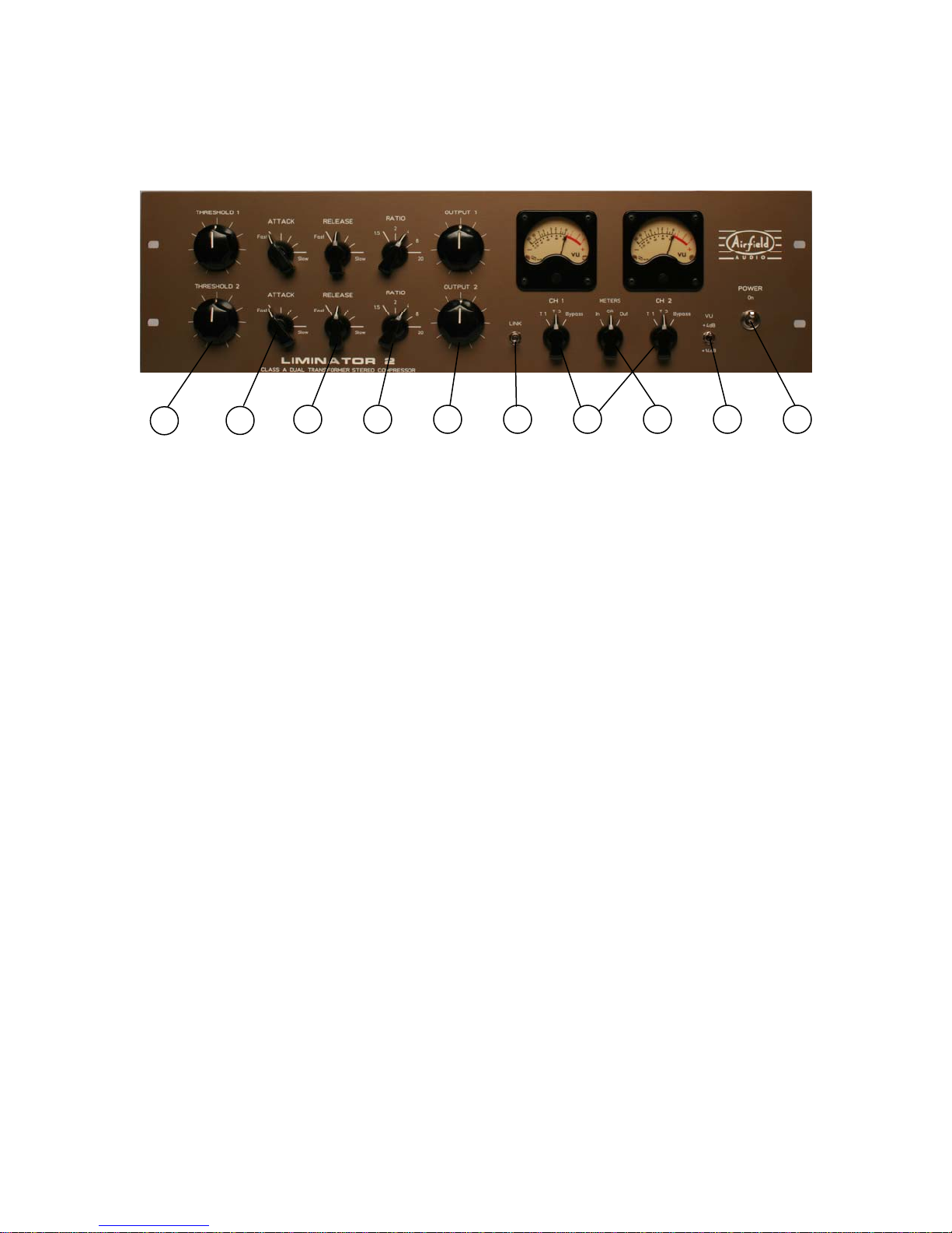
13. T1 / T2 / Bypass switch. Select one of two input transformers. T1 is a medium
impedance Jensen transformer. Select it for clean, uncolored, accurate, flat
response; perfect for mixing, mastering and pristine tracking. T2 is a lower
impedance Sowter transformer; select it when thicker musical harmonics and
richer tone are desired for tracking or mixing. Select Bypass (true relay bypass)
for comparison between unprocessed and compressed signals.
14. Select LINK when both Liminator 2 channels are used together for stereo
recording, mixing or mastering. The gain reduction control voltages are thus
mixed, which stabilizes the sound-stage image and prevents drift between
channels. Connect a Link cable or Y cables (see page 3) between multiple
Liminator units for multi-channel mixing. Each channel’s controls will remain
individually operational for compression settings, and are usually set identically.
With LINK switch in down position, channels operate in dual mono mode.
15. Unbalanced operation. The Airfield Audio Liminator 2 works fine in unbalanced
audio systems. Typically, input and output XLR cables (with pin 1 and 3 joined
together) wired to ¼” or RCA connectors will do the job. For proper operation of
THRESHOLD control, ensure that the output of your source device delivers a
good hot +4dB (0 VU) signal level.
- 6 -
www.airfieldaudio.com

SPECIFICATIONS
INPUT IMPEDANCE: 15KΩwith Transformer 1, Balanced, Pin 2 hot
1.2KΩwith Transformer 2, Balanced, Pin 2 hot
OUTPUT IMPEDANCE: 75ΩBalanced, Pin 2 hot
FREQUENCY RESPONSE: ± 0.25dB, 20 Hz to 20 kHz
- 2dB at 10 Hz, -2dB at 68 kHz with Transformer 1
- 2dB at 10 Hz, -2dB at 120 kHz with Transformer 2
NOISE: less than -80 dB, 20 Hz to 80 kHz, -92 dB typical below operating level
DISTORTION: less than .02% THD at unity gain, 4dBu input level
.1% THD at 24 dBu input level
MAXIMUM OUTPUT: + 32 dBu into 600Ω
GAIN REDUCTION RANGE: 0 ~ 20 dB
CROSSTALK: -89 dB @ 1KHz, + 4dBu signal level
ATTACK: 5, 30, 60, 100, 150 milliseconds
RELEASE: .1, .3, .6, 2, 6 seconds
GAIN REDUCTION ELEMENT: LD1 forward biased optical resistive module
METER: dB Gain Reduction
dB Input, dB Output (0VU = + 4dBu or +14dBu)
POWER REQUIREMENTS: 20 watts, 115 / 230 VAC, 50 / 60Hz
FUSE TYPE: 3AG slo-blo, ½ Amp for 115 VAC mains, ¼ Amp for 230 VAC mains
DIMENSIONS: 19” Rackmount 3U Chassis
DEPTH: 8” (200mm)
WEIGHT: 18 pounds (10 kg)
- 7 -
www.airfieldaudio.com

WARRANTY AND REGISTRATION
Airfield Audio equipment is covered by a limited warranty against manufacturing defects
in materials and craftsmanship for a period of two years from date of original purchase.
Under the terms of this warranty, Airfield Audio Inc. will repair or replace the part or
parts of the product which prove to be defective (except meter lamps, which are
guaranteed for 6 months from date of purchase), provided the purchaser gives Airfield
Audio prompt and satisfactory proof thereof.
If the equipment requires warranty repair, please contact your dealer or Airfield Audio by
telephone, fax or email. The purchaser’s sole remedy shall be to return the product to
Airfield Audio, where the defect will be repaired at no charge for parts and labor. All
returns to Airfield Audio require a return authorization number and must be in original
packaging, shipped to Airfield Audio via insured freight at the owner’s expense. Charges
for transportation costs and damage in transit are not covered by this warranty. The
equipment will then be returned via prepaid, insured freight, method and carrier to be
determined solely by Airfield Audio.
Airfield Audio Inc. is not responsible for damage from abuse or for any claim including
but not limited to property damage, loss of revenue, incidental or consequential damage
of any kind whatsoever which may result from failure of this product.
--------------------------------------------------------------------------------------------------------♫
MODEL____________________________ SERIAL #_________________________
PURCHASE DATE____________________ SUPPLIER________________________
OWNER________________________________________________________________
ADDRESS______________________________________________________________
EMAIL_________________________________________________________________
- 8 -
www.airfieldaudio.com
Table of contents
Other Airfield Audio Recording Equipment manuals