Airflow DUPLEXBASE PT 500 Quick start guide

Installation, use and maintenance manual
AIR HANDLING UNITS
DUPLEXBASE PT
500, 900,1800, 2800, 3500
Version: 02
Issue: 13.08.2021
Part no: 80001136 – Issue 2 01/23

2
Dear customer,
Thank you for choosing our product.
This manual contains all necessary instructions, information, and recommendations for safe and
correct equipment installation and commissioning. Please read the manual carefully and follow the
instructions included in this manual.
Symbols explained
Items or sections marked with Ü (or with a grey background) apply only to ventilation units
manufactured in compliance with the hygienic requirements of Regulation VDI 6022 (indicated on the
identification plate, see following chapters).
Important notices
•Electrical connections, commissioning and adjustment of the appliance may only be
carried out by qualified electrical engineers.
•Before the installation and commissioning of the appliance carefully read the installation,
use and maintenance manual, the controller operation manual and, where applicable, the
service documentation.
•The appliance and all its accessories must be installed and used in compliance with the
design, technical conditions specified by the manufacturer and applicable legislation and
technical standards in effect.
•The appliance may not be installed and operated in an aggressive environment that could
damage its external and internal mechanical parts.
•Before putting the appliance into permanent operation an initial inspection report on the
appliance´s power supply must be provided.
ÜBefore putting the appliance into operation an approval test (see VDI 2079 and DIN EN
V 12599) of the entire HVAC system of which the appliance forms part must be conducted.
The test must include the examination of hygienic requirements as per VDI 6022 and must
be documented. The user must be able to present the approval test report at any time. If the
above requirements are not met, the manufacturer cannot ensure compliance with hygienic
requirements.
The manufacturer is not liable for any damage caused by
•unprofessional installation and operation that is not in compliance with the operation and
maintenance manual and general practices applied during installation and operation of
HVAC equipment and control systems.
•using the equipment to other purposes than stated in the Chapter 3.2 Intended use.

3
Contents
1. Safety instructions ............................................................................................ 4
1.1. General safety ................................................................................................ 4
1.2. Operational safety........................................................................................... 4
2. Storage and transport ....................................................................................... 4
3. Description ......................................................................................................... 5
3.1. General ........................................................................................................... 5
3.2. Intended use ................................................................................................... 6
4. Installation.......................................................................................................... 6
4.1. Safety instructions .......................................................................................... 6
4.2. Hygienic instructions and requirements .......................................................... 6
4.3. Configuring orientation of the unit ................................................................... 7
4.4. Installation ...................................................................................................... 8
4.5. Ductwork connections ..................................................................................... 9
4.6. Connecting the condensate drain pipe ............................................................ 9
4.7. Installing air filters ......................................................................................... 10
4.8. Installing, connecting and filling liquid manometers ....................................... 11
4.9. Installing hot water heating coil ..................................................................... 12
4.10. Installing mixing valve of hot water air heater ................................................ 13
4.11. Installing shut-off dampers e1, i1 .................................................................. 13
4.12. Installing flexible flanges ............................................................................... 13
4.13. Installing and connecting water chiller to the cool source .............................. 13
4.14. Installing mixing valve of the water chiller ..................................................... 13
4.15. Installing direct chiller ................................................................................... 13
4.16. Installing electric heater / pre-heater ............................................................. 14
4.17. Installing manometers to control constant flow and constant pressure .......... 14
5. Electrical connection, commissioning, description of controls ................... 14
6. Hygienic instructions for compliance with VDI 6022 ..................................... 14
6.1. General instructions ...................................................................................... 14
6.2. Required qualifications of personnel as per the type of activity ..................... 15
7. Access to the unit using the internet ............................................................. 16
8. Package disposal............................................................................................. 16

4
1. Safety instructions
1.1. General safety
•Only adults sufficiently familiar with the operation and maintenance manual may operate the
equipment.
•The user must not tamper with or modify any part of the equipment, particularly the power supply
lines!
•Only professional service technicians with relevant qualifications may perform equipment repairs.
Unprofessional repairs are very risky and may result in loss of warranty.
•Before opening the equipment´s door for cleaning, filter replacement or general maintenance
always make sure that the equipment is disconnected from power supply and prevent its
reconnection by another person.
•For rules of connecting air duct please see chapter 4.5.
•If the equipment has been out of operation for a prolonged period of time, extra care should be
taken when putting it back into operation.
1.2. Operational safety
•The indoor version of the unit is intended for a basic environment - ambient temperatures must be
between +5 and + 55 °C with relative humidity up to 60 % (60 % relative humidity up to 20°C). If
the appliance is located elsewhere, its sufficient protection must be ensured.
•The appliance may be operated within the temperature range of ventilation air between -25 and
+40 °C with relative exhaust air humidity up to 80%, in an environment where there is no risk of
fire or an explosion of flammable gases and fumes, and air transported must not contain organic
solvents or aggressive substances that might damage mechanical parts of the unit. If there is a
danger of such gases and fumes temporarily entering the duct system (e.g. during floor bonding,
painting), the unit must be switched off sufficiently in advance.
•In the event of a failure the appliance must be disconnected from power supply as soon as
possible!
•The water chiller in all versions must be filled with an antifreeze solution with sufficient thermal
resistance, or it must be drained for the period during which outdoor temperature might fall below
+5°C. We recommend draining water from the chiller with pressurized air, not using a gravity flow!
•Appliances with hot water heaters
•Must be permanently connected to power supply to provide for the anti-freeze protection of the
hot water heater. In the case of a prolonged power outage the heating medium must be
drained from the hot water heater including the control set. We recommend draining water
from the heater with pressurized air, not using a gravity flow!
•It may only be operated if the heating system including the hot water heater and control set
are filled with a heating medium and air bled; also applies to periods outside the heating
season! In the case when the heating system including the hot water heater and control set
are not filled with a heating medium, the appliance must be drained of the remaining heating
medium, dried properly and disconnected from power supply.
•The appliance is designed for environments with Class ETA 1 extract air; in environments with
extract air Class ETA 2 and ETA 3 it is necessary to comply with conditions specified in the
chapter 4.2.
2. Storage and transport
•The appliance may only be stored in dry, covered places with ambient temperatures between
-25°C and +55 °C in such a way that its surfaces that are to be in contact with transported air
remain protected against the weather and stay dry and clean.
•Packaging may not be removed until immediately before the installation of the appliance in its
operating position. If that is not the case, all parts must be checked for cleanliness before
installation and thoroughly cleaned if necessary.
•The appliance must not contain any operational liquids (e.g. water in the hot water heater, water
chiller etc.) during storage and transport.
•The appliance may only be transported on handling blocks (included). During transportation the
appliance must be protected against mechanical damage and water penetration and all openings
must be covered with protective covers.

5
•During transportation the appliance must be secured against falling. The mode of transport must
also eliminate any falls of the appliance or instances of the appliance getting loose.
•Activities near the unit such as grinding, cutting and other ancillary works that could irretrievably
damage the surface or individual parts of the unit are prohibited.
Solely permitted methods of handling
3. Description
3.1. General
Duplexbase PT series ventilation units with heat recovery are compact appliances containing in a
single cabinet two independently powered fans with flexibly mounted engines, a highly efficient heat
recovery exchanger assembled from thin-walled plastic boards for the recovery of heat/cool, a by-pass
damper, slide-out filters and drainage trays, and depending on accessories selected also an
integrated heater, chiller, shut-off dampers, flexible flanges and a control system.
lifting straps
support blocks
Duplexbase PT 500
900 1800 2800 3500
B (mm) 620 720 725 1100 1290
a
1. Exhaust fan
2. Exhaust (extract air)
3. Supply air filter
4. Intake (supply air)
5. Junction box
6. Exhaust air filter
7. Intake (extract air)
8. Exhaust (supply air)
9. Preheater
10. Bypass flap
11. Condensate drain
12. Heat recovery core
13. Cooler
14. Reheater
15. Supply fan
B
min. fork distance 800mm
134 5 6 7 82
11 12 13 14 159 10

6
3.2. Intended use
Duplexbase PT series ventilation units with heat recovery are intended for the comfort ventilation
and possibly hot-air heating and cooling of flats and houses, small plants, workshops, schools,
restaurants, cooking facilities and industrial halls or for similar applications with a basic
environment. The use of the unit must be in compliance with the Regulation of the Commission
(EU) 1253/2014.
4. Installation
4.1. Safety instructions
•During installation make sure no damage or deformation is caused to the case of the appliance
(e.g. as a result of handling operations).
•After setting the appliance in place check it for stability and secure it in this position against
moving.
•During handling and installation observe all rules of safe work (including work at heights and work
with suspended loads) and use appropriate work and safety equipment.
•Lifting and binding equipment may only be operated by trained personnel.
4.2. Hygienic instructions and requirements
•If installation is interrupted or heavy dusting occurs, cover all openings of the appliance in such a
way so as to ensure that surfaces to be in contact with transported air remain protected against the
weather and stay clean and dry.
•If long-term high relative humidity (short-term more than 90 % or more than 80 % for three
consecutive days) is likely to occur with the subsequent moistening of filters (e.g. in areas with
frequent fogs, frequent and long rains, flying snow etc.), suitable measures must be taken to
prevent microbiologic growth. Recommended measures include more frequent hygienic checks as
per VDI 6022 or shorter filter replacement intervals. Another option is the preheating of air using an
appropriate control devices, or the appliance must be put out of operation for the period when filters
are at the risk of moistening (if the type of operation allows this).
•Should such weather conditions occur at the site of installation that would cause the dew point to be
exceeded in the supply air region of the heat recovery exchanger, or an independent cooling
system is installed in ventilated rooms, Duplexbase PT units may only be used provided that it has
been arranged via appropriate measures that the dew point will not be exceeded in the heat
recovery exchanger. The typical weather of central Europe makes this condition almost impossible.
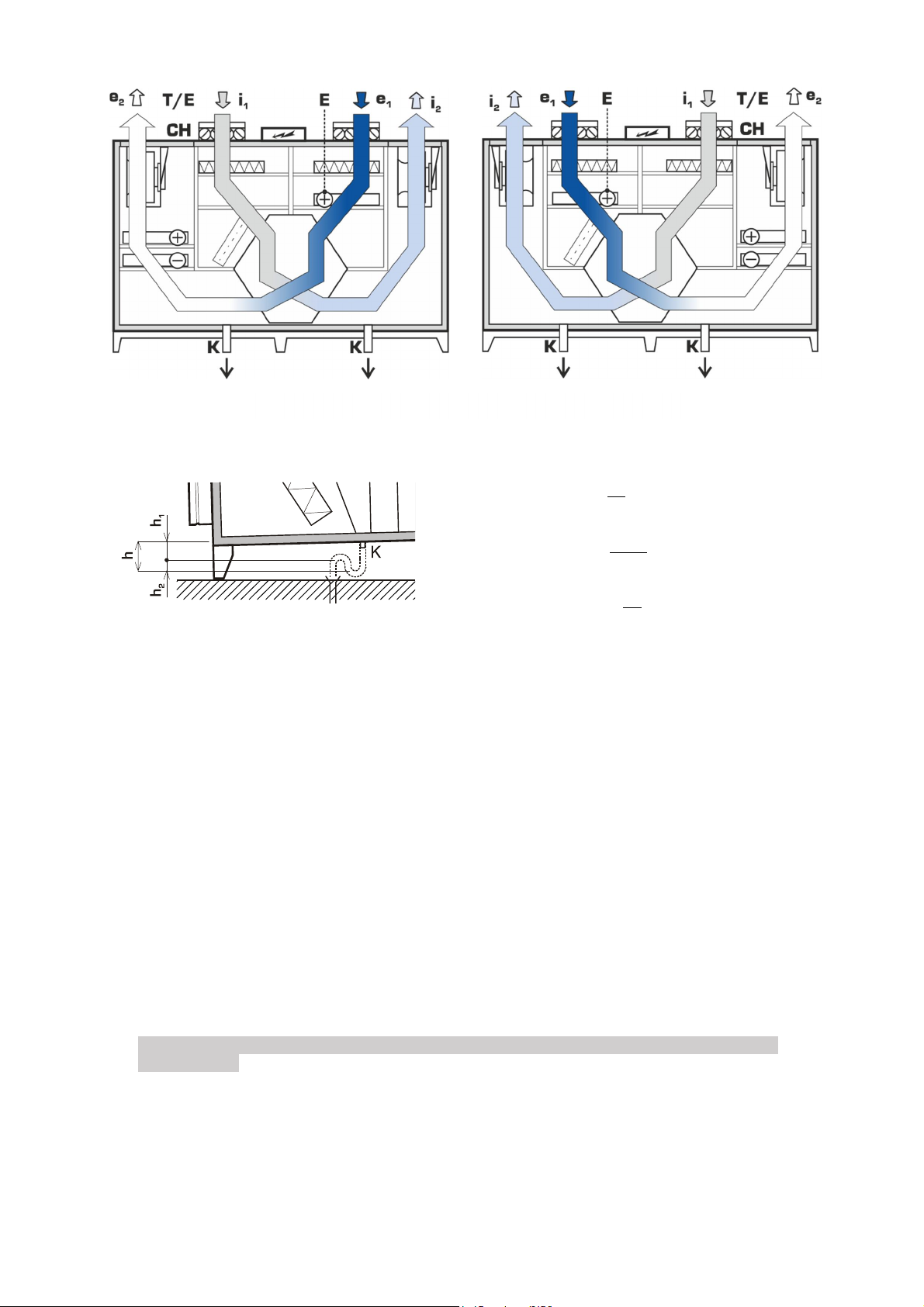
•The e1/ODA air supply chamber has no water drain. An accessible and cleanable chamber with a
drain of precipitated water must be installed upstream the outdoor air inlet into the appliance.
•The HVAC network of appliances operated in an environment with Class ETA 2 extract air must be
arranged for operation in such a way so that positive pressure is on the supply air side downstream
the heat recovery unit; in an environment with Class ETA 3 extract air the HVAC network must be
arranged for operation in such a way so that positive pressure is on the supply side against the
exhaust side. This must be ensured under all operating conditions of the system. For details see
EN 13779.
ÜIn compliance with hygienic standard VDI 6022 HVAC systems must be equipped with shut-off
dampers to ensure the automatic closure of the system so that no air can flow freely through the
system. Shut-off damper of the fresh air supply (ODA) must be thermally insulated. It is
recommended using shut-off dampers available as an accessory. It is the responsibility of the
planner / specialist installation firm to comply with this requirement.
ÜDuplexvent series appliances have a single-stage filtration system. Appliances in a hygienic version
in compliance with hygienic standard VDI 6022 must have at least Class ISO ePM1 50% (F7) filter
fitted on the inlet (applies to outdoor air e1/ODA Class ODA 1 and ODA 2). When outdoor air is
Class 3, a Class ISO ePM10 50% (M5) filter must be fitted in the duct upstream the outdoor air
inlet into the HVAC unit; alternatively, a Class ISO ePM10 50% (M5) filter may be installed in the
HVAC unit and a Class ISO ePM1 50% (F7) filter in the duct at the e2/SUP outlet from the unit.
Note: air filters ISO ePM10 50% (M5) and ISO ePM1 55% (F7) are separately supplied
accessories.
ÜAppliances in a hygienic version in compliance with hygienic standard VDI 6022 may be operated
only if the use of recirculating air is suitable for hygienic reasons or the arrangement of operation

7
of the HVAC network ensures positive pressure in the supply section of the appliance against the
extraction section.
4.3. Configuring orientation of the unit
The versatile design of sizes 500, 900, 1800, 2800 and 3500 allows adjusting the direction of air flow
through the appliance; it can be configured which of the fans will be supplying and extracting the air.
The direction of air flow can be configured once the unit is switched ON for the first time.
1. Open the door of the unit. Check the labels on the fans to learn which fan is marked M1 and M2.
2. Connect the control panel CP Touch to the unit. Turn the unit ON. The control panel will report an
error by showing a yellow triangle on the top of the display.
3. Click on the symbol of the error. The control panel will display the message Orientation is not set.
4. Proceed back to the default screen, click on the cogwheel in the bottom left corner.
5. Click on the Settings symbol in the top right corner.
6. Enter the service menu password. The password is available to authorized partners.
7. Proceed to the parameter 3.2.2 on the control panel. Set up the fan M1 or M2 as M-SUP (supply
fan).
The operation of the unit is blocked until the parameter MSUP is configured to M1 or M2.
Identify individual ports based on the configured unit orientation and mark the ports by labels (part of
delivery).
By default, the unit is equipped with filters of different filtration classes. Make sure the filters are
placed correctly according to the orientation of the unit. For more information see Chapter 1.1.
Description:
e1 (ODA) – supply air
intake
e2 (SUP) – supply air
exhaust
i1 (ETA) – extract air
intake
i2 (EHA) – extract air
exhaust
Position of intake and exhaust, M2 is configured as a supply fan (M-SUP).

8
After each change of unit orientation make sure that the filters of supply air (resp. extract air) are
positioned in the supply (resp. extract) section of the unit. For more information see Chapter 4.7.
4.4. Installation
•Before installation remove the wooden transport planks.
•Fit the appliance in such a way that the prescribed handling spaces are observed:
•The appliance is placed on height-adjustable stand feet included in delivery (4 pieces in sizes 500
and 900, 6 pcs in size 1800, 2800 and 3500).
•Level the appliance horizontally on both longer and shorter side. Use adjustable stand feet.
Adjustable bases must be fully screwed into the stand feet when manipulating with
the unit. Only after putting the unit into the final installation position may the feet
height be adjusted. Failing to do so may cause irreversible damage of the feet.
Duplexbase PT 500
900 1800 2800 3500
T (mm) 600 600 1100 1100 1100
Plan view
View from the operator's side
Position of air intake and exhaust, M1 is configured as a supply fan (M-SUP).

9
•The unit must be secured against movement.
4.5. Ductwork connections
•Connect the HVAC duct following the design documentation. Make sure that the air exhausted at
i2 does not return back to the fresh air supply e1.
•Air duct must be connected to inlet ports in a way that a uniform flow rate is achieved in the whole
cross-section of inlet ports.
•A straight air duct being at least 1 m long must be firmly connected to extraction ports to achieve a
uniform flow rate in the whole cross-section of extraction ports.
•A duct being at least 2 m long must be always connected to fan outlets to prevent injury caused by
the fan’s impeller. This duct must be connected in such a way that it can be dismantled only by
using tools.
4.6. Connecting the condensate drain pipe
•The unit is equipped by two condensate outlets; these are used depending on whether an
integrated cooler is installed and what unit orientation is selected.
Use of condensate drains, Duplexbase PT without integrated cooler

10
Siphon height
ℎ1=∆
10 + 50 []
ℎ2=∆
2 ∙ 10 + 50 []
ℎ= 1,5∆
10 +100 []
Δp – maximum positive / negative working pressure in the compartment of the unit. The height of
condensate drain pipe h = 15 cm is sufficient for vast majority of installations.
•Connect one siphon trap (included in delivery) to each condensate outlet. Connect the siphon to
the sewer line.
•Make sure that the condensate pipe is passible all the way along including parts inside the unit
and the pipe slope is sufficient.
•Fill each siphon trap with water.
4.7. Installing air filters
The unit is supplied with separately packed filter cassettes. Filters of outdoor and extracted air feature
different filtration class in the default configuration:
•Filter with the class ISO ePM1 55% (F7) is the filter of outdoor air and it is placed in the
compartment e1 (ODA);
•Filter with the class ISO ePM10 50% (M5) is the filter of extracted air and it is placed in the
compartment i1 (ETA);
•Remove, unpack the cassettes and check their condition. Then install the cassettes in their correct
location based on the unit orientation, see pictures in the Chapter 4.3.
ÜUnpack and install air filters last, immediately before putting the unit into service to avoid their
contamination.
•Should any damage or contamination be detected, replace the filters with new ones. Spare filter
cassettes are to be ordered from the supplier. The supplier´s address and the spare cassette part
number are shown on the identification plate of the unit.
●Insert undamaged clean filters into the guide rails and secure them.
Use of condensate drains, Duplexbase PT with integrated cooler

11
Especially make sure that the arrow showing the direction of air flow through the filter cassette can
be seen from the side of the operator (the arrow is by the unit´s door) and that the arrow always
points towards the heat recovery exchanger!
●The unit is supplied with filter cassette labels unattached. Attach the relevant identification labels
near both filters (e.g. on respective unit door).
Unpack and install air filters last, immediately before putting the unit into service to avoid their
contamination.
Use original filter cassettes only! If different cassettes were used, the manufacturer cannot
guarantee their proper function!
ÜRecord the date of installing filters appropriately in e.g. the operational logbook.
4.8. Installing, connecting and filling liquid manometers
ÜLiquid manometers are a separately supplied accessory. Manometers are compulsory for hygienic
units in compliance with VDI 6022.
•Manometers are used for measuring the pressure loss of air filters. During installation follow the
visual instructions supplied with this optional accessory. After installation level the manometers
horizontally.
•Connect the manometers to collection points on the unit´s surface using tubes. Connect the tube
to the top of the manometer and run it to the metal bushing on the unit´s surface (also see a
separate manometer installation manual). The tube must always connect two matching connection
points identified by symbols “+” and “F+” and “-“ and “F-“ (cannot be combined). Make sure that
tubes from just one filter are connected to the manometer.
•Attach the relevant label near each manometer. Fill out the boxes with the filter grade and record
the flow rates and pressure losses of the clean filter (initial pressure loss) and when clogged (final
pressure loss) using data from the table below; the values must be adjusted on the basis on actual
air flow rates through the unit. The unattached label without information filled out is included.
Duplexbase PT 500
Filter type Flow rate (m3/h) 100 200 300 400 450
ISO
ePM1 55% (F7)
Initial pressure loss (Pa) 18 45 78 120 144
Final pressure loss (Pa) 200 200 200 200 200
ISO
ePM10 50% (M5)
Initial pressure loss (Pa) 5 17 36 62 78
Final pressure loss (Pa) 200 200 200 200 200
Duplexbase PT 900
Filter type Flow rate (m3/h) 400 500 600 700 800
ISO
ePM1 55% (F7)
Initial pressure loss (Pa) 58 78 100 124 150
Final pressure loss (Pa) 200 200 200 200 200
ISO
ePM10 50% (M5)
Initial pressure loss (Pa) 15 23 33 44 58
Final pressure loss (Pa) 200 200 200 200 200
2.
1. 2.
1.

12
Duplexbase PT 1500
Filter type Flow rate (m3/h) 800 1000 1200 1500 1800
ISO
ePM1 55% (F7)
Initial pressure loss (Pa) 13 21 30 47 68
Final pressure loss (Pa) 200 200 200 200 200
ISO
ePM10 50% (M5)
Initial pressure loss (Pa) 2 4 5 8 11
Final pressure loss (Pa) 200 200 200 200 200
Duplexbase PT 2500
Filter type Flow rate (m3/h) 800 1000 1500 2000 2200 2500
ISO
ePM1 55% (F7)
Initial pressure loss (Pa) 13 18 31 48 55 67
Final pressure loss (Pa) 200 200 200 200 200 200
ISO
ePM10 50% (M5)
Initial pressure loss (Pa) 3 4 8 12 15 18
Final pressure loss (Pa) 200 200 200 200 200 200
Duplexbase PT 3500
Filter type Flow rate (m3/h) 1000 1500 2000 2500 3000 3500
ISO
ePM1 55% (F7)
Initial pressure loss (Pa) 10 13 24 30 47 64
Final pressure loss (Pa) 200 200 200 200 200 200
ISO
ePM10 50% (M5)
Initial pressure loss (Pa) 2 4 6 11 15 22
Final pressure loss (Pa) 200 200 200 200 200 200
Note: Values in the tables apply to external static pressure 200 Pa. Different pressure requirements
may result in a different situation. If needed, the detailed initial and final pressure loss data of the
filters are available on request from the supplier of the unit.
•Make sure that the position of the label makes it possible to regularly inspect the values recorded.
•Unscrew the rotating knob as much as possible to set zero on the scale (the bottom knob
identified by - +), then screw it back by approximately two full turns to have leeway to make
settings in both directions.
•Unscrew the FILL plug (the top knob) and keep filling the machine with measuring liquid (included
in delivery) until the liquid is visible near the zero mark on the scale. Use the bottom knob to set
the value on the scale precisely to zero. Screw the top filling plug in.
After installing the manometers do not tilt the machine or the door (if they are installed on the
door). Measurement liquid might leak out.
4.9. Installing hot water heating coil
During the mechanical installation of the hot water air heater follow the manual supplied with this
optional accessory.
The supply (and top-up) water should fulfil especially the following criteria:
•The water must be limpid and colourless.
•The pH value of water must not be lower than 7. If water contains dissolved neutral salts its pH
value is to be between 8,5 and 9,5. Soda lye or trisodium phosphate (Na3PO4)can be used for
alkalinisation.
•The content of carbon dioxide in an ion and non-ion form is to be as small as possible.
•The remaining supply water hardness should be lower than 7 mmol/l (at q < 23 kW/m2) and 5
mmol/l (at q > 23 kW/m2).
•To soften the water, the following chemicals can be used: trisodium phosphate Na3PO4 or cation-
exchange resin (in case water is harder than 7 mmol/l; circuits with high volume of water; when
electrical boilers and radiation boilers are present).
•The amount of calcium ion in the water up to 3,5 mmol/l (at q < 23 kW/m2) and up to 1,8 mmol/l
(at q > 23 kW/m2).
•All CO2 up to 75 mg/l (at q < 23 kW/m2) and 10 mg/l (at q > 23 kW/m2).
Exact composition of top-up water is mentioned in the norm ČSN 07 7401, in the annex, Table 1.

13
The following rules must be adhered to during the installation of the heater:
•The maximum permitted temperature of heating medium is 110 °C and operational positive
pressure up to 1.0 MPa.
•For the proper operation of the control set of the hot water heater the heating system must be
fitted with a circulation pump of suitable power that will fully cover its pressure loss. The pump,
which is supplied with the control set, is designed solely to cover the pressure loss of the water
heater!
•If the unit is not equipped with a shut-off damper on outdoor air inlet e1, a tight, thermally isolated
shut-off damper must be installed in the duct upstream the unit (a type with a servo drive with
emergency stop, i.e. the damper automatically shuts in the event of a power outage).
•The heating system must be equipped with a sludge filter in the inlet into the unit.
•The heating circuit must be equipped by a safety valve and a sealed pressure vessel. Heat carrier
– untreated water or water treaded as per the rules above, properly bled. Recommended
hardness of water in the range 7 – 12°dH. In case of higher water hardness we recommend its
softening. Fluid with antifreeze protection (e.g. ethylene glycol) can be used as heat carrier if
necessary. We recommend isolating the inlet and outlet piping.
Electrical installation may be carried out only by a person having the required electrotechnical
qualification.
You will find the wiring diagram in the unit’s Technical Specification or in the selection SW of
Duplexvent units, tab Controls > Wiring diagram.
4.10. Installing mixing valve of hot water air heater
During the mechanical installation and connection of the mixing valve of the hot water air heater follow
the manual supplied with this optional accessory.
4.11. Installing shut-off dampers e1, i1
During the mechanical installation and connection of the servo drive of shut-off dampers follow the
manual supplied with this optional accessory.
4.12. Installing flexible flanges
During the mechanical installation of flexible flanges follow the manual supplied with this optional
accessory.
4.13. Installing and connecting water chiller to the cool source
•During the mechanical installation of the water chiller follow the manual supplied with this optional
accessory.
The following rules must be adhered to during the installation of the water chiller:
•The water chiller in all versions must be filled with an antifreeze solution with sufficient thermal
resistance, or it must be drained as long as the outdoor temperature might drop below 0°C.
•Maximum permitted operating positive pressure is 1.0 MPa!
•The inlet of the chilled water system into the unit must be equipped with a sludge filter.
4.14. Installing mixing valve of the water chiller
During the mechanical installation and connection of the control manifold of the hot water heater follow
the instructions supplied with this optional accessory.
4.15. Installing direct chiller
•During the mechanical installation of the direct chiller follow the manual supplied with this optional
accessory.
•During the connection of the direct chiller follow the instructions of the supplier of condensation
units and connecting pipes.

14
4.16. Installing electric heater / pre-heater
•During mechanical installation and electrical connection follow the manual supplied with this
optional accessory.
•Electrical connections may only be made by a qualified electrician authorized to service power
supply networks.
4.17. Installing manometers to control constant flow and constant
pressure
During mechanical installation and electrical connection follow the manual supplied with this optional
accessory.
5. Electrical connection, commissioning,
description of controls
•The electrical equipment of the unit is designed by following standards in effect for electrical
connections to power supply network TN-C, TN-S, TN-C,S. The appliance may only be connected
by a qualified electrician. The appliance is provided with external connections for equipotential
bonding.
•The wiring diagram of the equipment is shown in the documentation supplied along with the unit.
Instructions for and the diagrams of electrical connections of optional accessories are included in
the documentation sets of these accessories.
•The power supply line to the equipment must be provided with a disconnecting device - a service
switch for disconnecting from power supply - the opening contacts of which are at least 3 mm
apart at all poles. This disconnecting device must be installed within an appropriate distance from
the appliance. The protection device included as a standard with delivery may act as such a
disconnecting device provided that the switchboard is located within reach of the appliance.
•Commissioning may vary depending on the type of control system. Commissioning is carried out
by a trained technician following the separate documentation set included.
•The controls are described in a separate guide on operating the control system.
The unit is to be protected using a breaker with characteristics "C".
In case of using additional overcurrent protection against accidental direct or indirect contact, it is
necessary to use a special circuit breaker designed for frequency inverters and switching
sources. It is a protector sensitive to alternating pulsed DC residual currents, resistant to current
surges 5 kA.
6. Hygienic instructions for compliance with VDI
6022
6.1. General instructions
ÜBasic hygiene-related requirements are outlined in the Chapter 4.2.
ÜThe appliance has been manufactured in a hygienic design that complies with all requirements of
the VDI 6022 standard for the hygiene o HVAC device. In order to meet those requirements during
operation it is essential to ensure for the appliance to be operated, maintained, inspected and
cleaned by sufficiently qualified personnel in accordance with instructions contained in the
operation and maintenance manual. It is also essential to ensure for the remaining components of
the HVAC system (HVAC distribution systems, distribution elements, ancillary devices, noise
silencers etc.) to meet all hygienic requirements of the VDI 6022 standard and be operated in
compliance with those requirements.
ÜIf long-term high relative humidity (short-term more than 90 % or more than 80 % for three
consecutive days) is likely to occur with the subsequent moistening of filters (e.g. in areas with
frequent fogs, frequent and long rains, flying snow etc.), suitable measures must be taken to
prevent microbiologic growth. Recommended measures include more frequent hygienic checks as
per VDI 6022 or shorter filter replacement intervals. Another option is the preheating of air using

15
an appropriate control devices, or the appliance must be put out of operation for the period when
filters are at the risk of moistening (if the type of operation allows this).
ÜAir duct including accessories with autonomous regulation of operation is to be connected on the
fresh air supply. Such duct will, in compliance with the regulation VDI 6022, provide for
appropriate treatment of supplied fresh air to prevent air filter from getting wet. In case the duct is
not connected or if it does not include such accessory, the appliance is to be put out of operation
as long as the risk of air filters to get wet persists (thick fog, snowing).
ÜOperators must be familiar with the tasks and functions as well as the individual components of
the appliance.
ÜThe appliance must be regularly inspected, cleaned and maintained by sufficiently qualified
personnel (see the following chapter).
ÜRegardless of their qualifications, personnel must undergo hygiene training (see the following
chapter).
ÜThe user must be able at any given time to provide evidence as to the qualifications of operators.
If sufficient number of qualified operational and service staff are not available, those activities must
be commissioned to a specialist company that will be responsible for the proper operation of the
appliance.
ÜThe user has an obligation to carry out regular hygiene inspections of the appliance every 3 years
(see following chapters).
ÜThe appliance must not be operated without air filters. The filter grade of supply fresh air must be
at least ISO ePM1 50% (F7). The filter grade of exhaust air must be at least ISO ePM10 50%
(M5).
ÜIf the appliance has been out of operation for a longer period of time, it must be cleaned
thoroughly before recommissioning; if stricter hygienic requirements apply, wiping disinfection
must be carried out.
ÜAfter disinfecting make sure that no toxicologically suspicious or odour-active substances enter
supply air!
ÜThe user has an obligation to appropriately record the appliance's operation (e.g. in the
operational logbook).
6.2. Required qualifications of personnel as per the type of activity
Activities Operators Inspection Maintenance Repairs
Required
personnel
qualifications
No special
professional
qualifications
Professional engineering
qualifications in building
maintenance, familiarity
with measurement
procedures for the
hygiene inspections of
HVAC devices
Professional qualifications in
electrical or metal engineering with
relevant experience in the field of
HVAC (familiarity with equipment
design, measurement
technologies, equipment control
and function)**
Required hygiene
training of
personnel
Category B Category A Category B
** simple inspection and maintenance of the equipment (e.g. replacing filter cassettes, regular
cleaning of equipment etc.) may be carried out by personnel without professional qualifications who
received category B hygiene training
a) Category B hygiene training of personnel
ÜPersonnel must demonstrate familiarity with the following areas:
(1) Need for and the importance of hygiene during the operation of HVAC equipment
(2) Hygiene issues of individual aggregates carrying air through HVAC equipment
(3) Maintenance of HVAC equipment, the effects of its size on determining maintenance
intervals
(4) Simple measurement methods for checking HVAC equipment
(5) Actions to be taken in the case of occurrence of substances harmful to the environment and
their removal
(6) Personal protective measures in the area of hygiene during operation and service activities
(7) Key regulations (in particular regulations on accident control) and technical standards
(8) Handling chemical cleaning and disinfecting agents

b) Category A hygiene training of personnel
ÜPersonnel must demonstrate familiarity with the areas of category B training specifications and
additionally the following:
(1) Hygiene basics
(2) Significance of the various hygienic methods of air treatment
(3) Physical and chemical measurement methods, hygiene and microbiological inspection
methods
(4) SBS (Sick-Building-Syndrome) issues, symptoms of problems and possible causes
(5) Technical development and its practical applications
(6) Hygiene regulations and technical rules for the operation of HVAC equipment
7. Access to the unit using the internet
Ventilation units Duplexbase PT equipped with control system RD5 1 can also be controlled using
a web browser. This allows the user to do the following, either from a local network on site or
through the Internet:
●Change user setting of the unit;
●Watch the unit’s operational parameters including error messages;
●Browse the unit’s operational history;
●Set e-mail notification with Alarm or Warning messages for up to three e-mail addresses.
You will find more information in the Guide on controlling ventilation units Duplexvent equipped with
RD5 control system.
8. Package disposal
Materials marked with the symbol are recyclable. Put these materials in the respective bins in
order to be recycled.
PAP – corrugated cardboard PE – polyethylene PP – polypropylene
FOR – wood PS – polystyrene
Please leave materials marked with the symbol at the community place used for waste disposal!
Disused ventilation unit sold on the EU market can be recycled in compliance with the
regulation 2012/19/EU.
1 Information regarding the control module your unit contains is shown on the unit’s name plate on the
Controls / Specification line. The information is also included in the unit’s Technical Specification.
If these instructions are not adhered to, the manufacturer cannot guarantee the permanent
maintenance of the unit´s hygiene parameters.
This manual suits for next models
4
Table of contents
Other Airflow Air Handler manuals
Popular Air Handler manuals by other brands

Vent-Axia
Vent-Axia Lo-Carbon PoziDry Pro 476310 Installation and wiring instructions

Daikin
Daikin Altherma 3 H HT ECH2O Series Service manual

RDZ
RDZ RNW 214 I Technical installation manual

Vaillant
Vaillant aroTHERM plus VWL 75/6 A S2 Series operating instructions

Carrier
Carrier 40RUM Series Installation, operation & maintenance manual

Bosch
Bosch BVA 2.0 Series installation instructions