Airflow Adroit DV51 User manual

Instruction Manual
INSTRUCTION MANUAL
DV51 DV51CH

2
DV51 DV51CH
INTRODUCTION .......................... . . 2
Safety ................................................ .3
Installation ....................................... . . . .3
Guarantee ............................................ .3
Intended use .......................................... .3
Disposal of the ventilation unit............................. .3
Safety signs used in the instructions ....................... .4
Installation options ...................................... .4
System description ..................................... .4
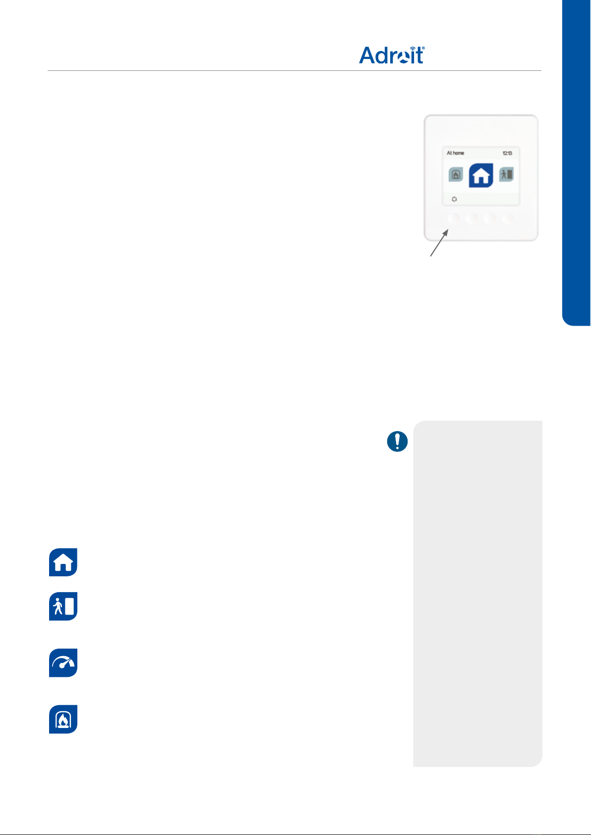
Ventilation unit control .................................. .5
Ventilation unit control options. ....................... . . . .5
Changing the ventilation mode ....................... . . . .5
Adroit DV51 ...................................... . . . .5
Adroit DV51CH .................................... . . . .6
Connecting the ventilation unit to the cloud service ....... . . . .7
Brightness of the light .............................. . . . .7
Guard function .................................... . . . .7
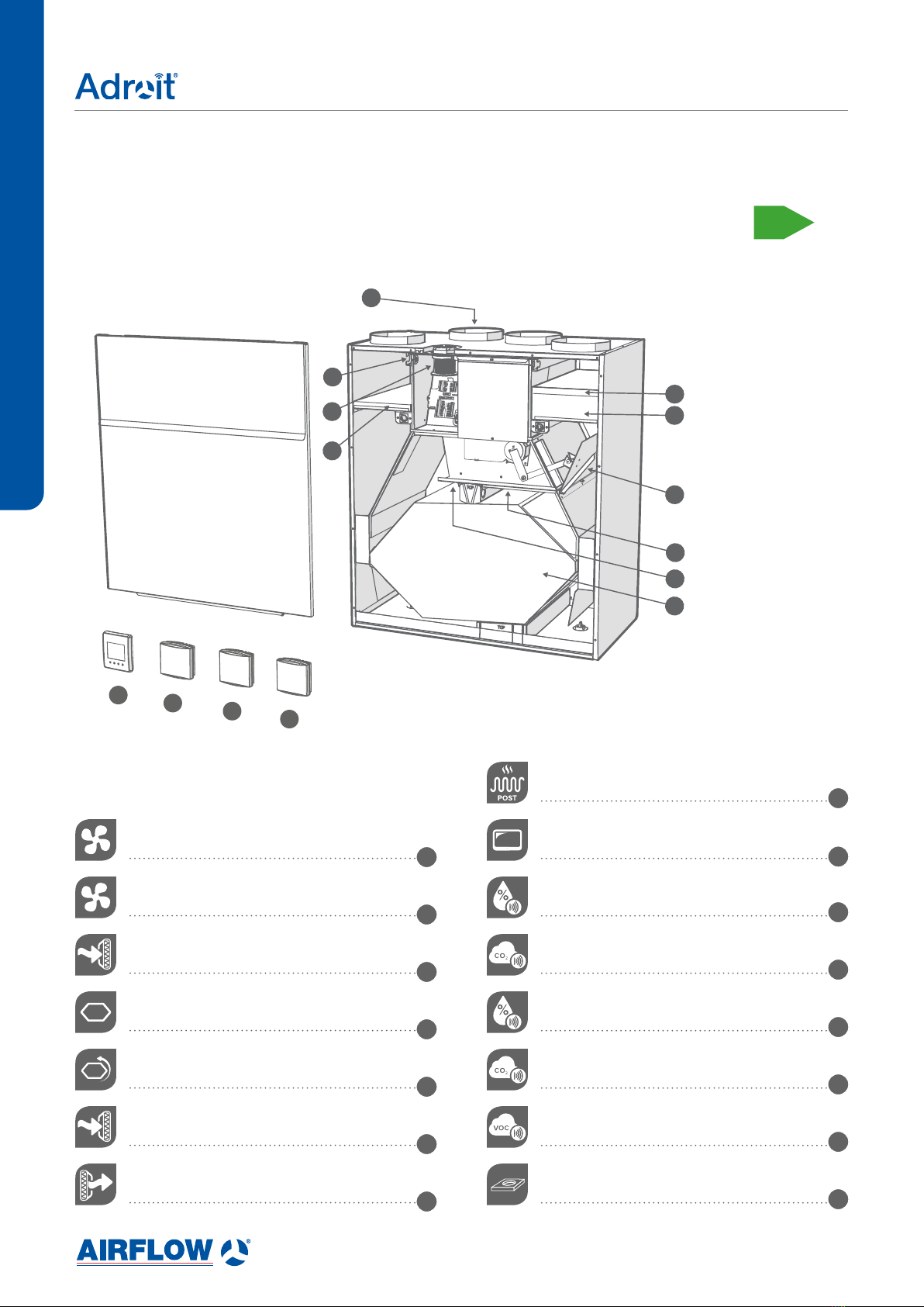
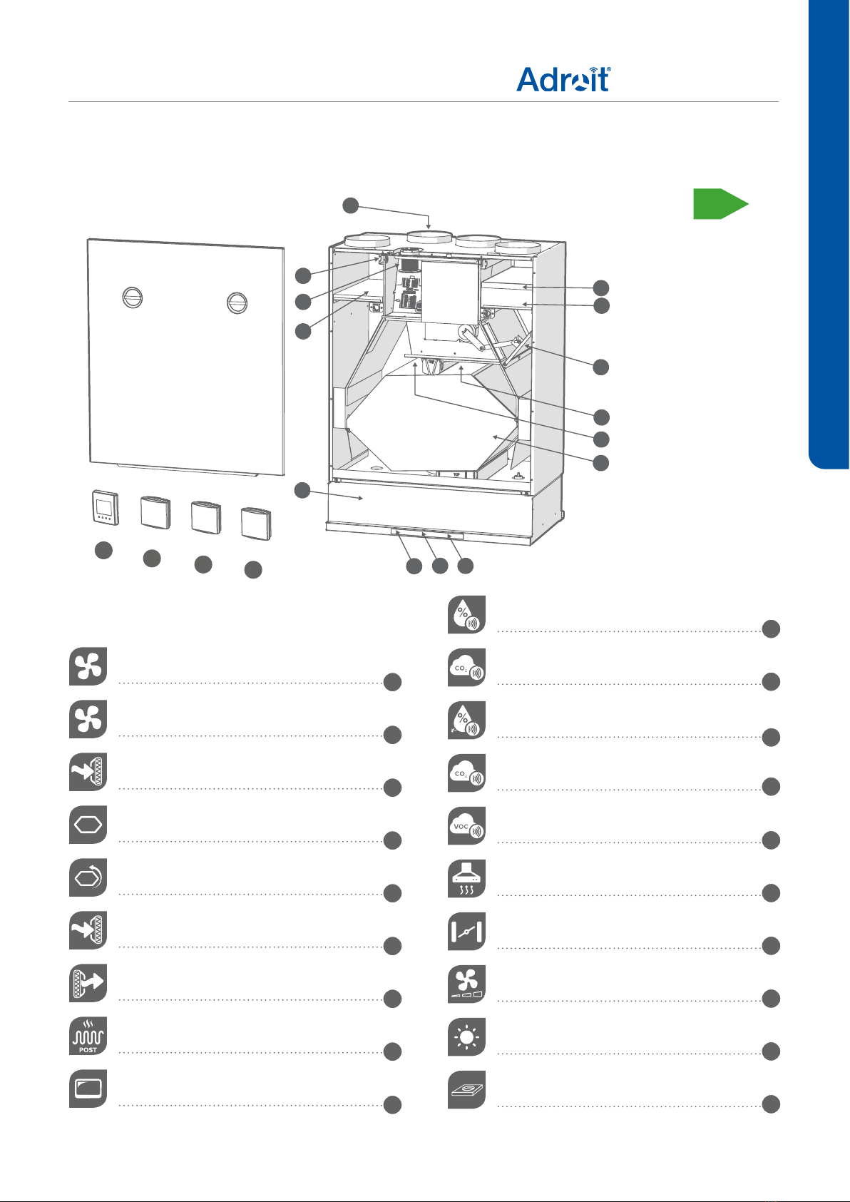
Main parts ............................................ .8
Adroit DV51 ...................................... . . . .8
Main parts ............................................ .9
Adroit DV51CH .................................... . . . .9
INSTALLATION ........................... 10
Mounting on the wall ................................... 10
External electrical connections ........................... 10
Removal of condensing water ............................ 10
Adroit DV51 ...................................... . . .10
Adroit DV51CH .................................... . . . 11
Installation of the Adroit Cooker hood ..................... 12
Measuring and adjusting the air ows of the ventilation unit..... 13
Measuring and adjusting the air ows of the cooker hood ...... 13
Standard ventilation ................................ . . . 13
Adjustment: ...................................... . . .13
Adroit DV51, DV51CH .................................. 15
Dimensions and duct outlets ............................. 15
MAINTENANCE .......................... 16
Adroit DV51, DV51CH .................................. 16
Before beginning maintenance work ....................... 16
Changing the lters .................................... 16
Cleaning the heat recovery cell ........................... 17
Condensing water ..................................... 17
Cleaning the fans ...................................... 18
Removing and cleaning the fans . . . . . . . . . . . . . . . . . . . . . . . . .18
Adroit DV51CH ....................................... 19
Cleaning the grease lter of the cooker hood . . . . . . . . . . . . . . . . 19
Removing and mounting the grease lter ............... . . .19
Light ............................................ . . . 19
NOTE
You can sign into your
Adroit account at: www.
airowadroitcontrol.com
CONTENTS
INTRODUCTION
TECHNICAL SPECIFICATIONS 20
Air ows and sound values .............................. 21
Internal electrical connection............................. 22
Adroit DV51 / Adroit DV51CH......................... . . 22
External electrical connection ............................ 23
Adroit Cooker hood ................................ . . 23
External electrical connection ............................ 24
Adroit DV51 ...................................... . . 24
External electrical connection ............................ 25
Adroit DV51CH .................................... . . 25
Brine heat exchanger................................... 26
Duct radiator operation ................................. 27
Duct radiator operation chart............................. 28
In the outdoor air duct .............................. . . 28
In the supply air duct ............................... . . 28
Exploded view and parts list ............................. 29
Adroit DV51 ...................................... . . 29
Adroit DV51CH .................................... . . 30
Conformity certicates.................................. 31

3© Airow - We reserve the right to make changes without prior notice
DV51 DV51CH
DIFFERENCES BETWEEN THE UNITS
• Size
• DV51CH is equipped with a cooker hood.
• DV51 is not equipped with a cooker hood but an Adroit cooker hood
can be added later on.
• Weight
GENERAL SAFETY INSTRUCTIONS
For safe and proper handling, it is necessary to know the basic safety
regulations and the intended usage of the ventilation system. Read this
manual before operating the ventilation unit. Keep this manual for later
use. In case of loss, you can download the manual from our website.
This user manual contains all important tips for operating the system
safely. This user manual must be observed by all persons who operate
and maintain the ventilation system.
Furthermore, observe all local accident prevention regulations.
Installation
Installation and setup should be carried out only by qualied experts.
Electrical installations and connections must be carried out only by an
approved electrician and in compliance with local regulations.
Installation options
There are two unit models available, left- (L) and right-handed (R).
The right-handed version, outdoor air blows into the unit from the
right. In the left-handed version, outdoor air blows into the unit from
the left side. The location of the lters, bypass damper, and brine heat
exchanger (not supplied as standard) is also mirrored in the
left-handed model.
GUARANTEE AND LIABILITY
• Demands on guarantee and liability are excluded if they are caused
by the following reasons:
• Unintended use of the ventilation system and the control unit
• Improper mounting
• Operating the ventilation system, if not installed correctly
• Ignoring advice for transportation, mounting, operation and
maintenance
INTENDED USE
All Adroit units have been designed to provide appropriate and
continuous ventilation, in such a way that people and structures will
remain healthy.
DISPOSAL OF THE VENTILATION UNIT
Do not dispose of electronic devices with household waste. Follow
local laws and regulations on safe and ecological disposal of the
product.
NOTE
For further information,
go to www.airow.com
INTRODUCTION
WARNING
The unit is not intended
for use by children
under 8 or by persons
with reduced sensory,
physical or mental
capabilities, or whose
lack of knowledge and
experience do not
ensure safe operation
of the unit.
Such persons can
use the unit under
supervision, or
by following the
instructions of someone
who is responsible for
their safety.
Children must be
supervised and not be
allowed to play with the
device.

4
DV51 DV51CH
INTRODUCTION
SYSTEM DESCRIPTION
Router
WLAN/
LAN
WLAN
%
away
from
home
Adroit Cloud
Adroit Adroit Control
Adroit Home
WLAN
INTERNET
WLAN / LAN
SENSORS
EXTERNAL
SWITCHES
ROUTER
MODBUS
HOME
AWAY
BOOST
WOOD
BURNER
CONNECTING WITH ADROIT HOME
1. Connect Adroit unit to the mains.
2. Connect one end of the network cable (RJ-45) to computer and
the other end to network connector on the Adroit unit.
3. Select on your computer: Start ►Computer ►Network
4. DoubleclickontheAirowicon.
5. Now you are connected to the Adroit Home service, you are able
to control the Adroit unit.
REGISTERING TO THE ADROIT CLOUD
1. Connect with Adroit Home (instruction above).
2. Select Settings.
3. Press connect button in Adroit Cloud Service section.
4. Registration Page is now opened.
5. Enter the following information
a. Device name- enter the desired name for the device
b. User name
c. E-mail address
d. Password
6. Press the create account button.
7. An e-mail with your log-in details will be sent to the e-mail given
during the registration process.
8. A verication e-mail will be sent to the e-mail address given during the
registration process.
9. Click on the link given in this e-mail to verify your e-mail address.
10. You are now connected to the Adroit Cloud.
NOTE
Following requirements:
Firefox, version 31 or higher
Opera, version 25 or higher
Chrome, version 31 or higher
Safari, version 7 or higher
The lastest browser versions on
mobile devices.
NOTE
The Adroit unit can also be
connected by network cable to a
router. In this case the Adroit unit
can be controlled via your laptop,
tablet, smartphone etc using a
network created by the router.

5© Airow - We reserve the right to make changes without prior notice
DV51 DV51CH
INTRODUCTION
IMPORTANT
Apartment-specic
ventilation units allows
residents to adjust the
ventilation efciency.
Ventilation is controlled
based on the need e.g.
through the cooker
hood, ventilation control
panel, or a separate
control centre. In order
to ensure that the
indoor air presents no
harm to health and
remains optimal also
for the structures of the
building, ventilation
must be kept on
without disruptions.
It is recommended that
ventilation be left turned
on during long holidays
also. This keeps the
indoor air fresh and
prevents humidity
from condensing in
the ventilation ducts
and structures. It also
reduces the risk of
moisture damage.
VENTILATION UNIT CONTROL
Ventilation unit control options.
Ventilation has to be constant for the indoor air to stay healthy
for the dwellers and the structures of the dwelling. Even for
longer holidays, it is not advisable to stop the ventilation,
because the indoor air will become stuffy and, during the
heating season, the indoor air humidity may condense in the
ventilation ductwork and structures, causing moisture damage.
You can control and automate the ventilation unit operation in
the following ways:
- By using an Adroit control panel installed in the building
- Through the Adroit Home local network connection and the
Web interface
- Through the Adroit Cloud Service and the Web interface
- Through a remote monitoring service or building automation
by using voltage signals or Modbus messages
- By using the front panel of the cooker hood; this control option
applies only to the DV51CH.
At home
Use this mode when the dwelling is occupied.
Away
Use this ventilation mode when the apartment is
unoccupied, e.g. during a trip or other long absence.
Boost
Fireplace mode
Use this mode when starting a re in the replace.
The mode is primarily used to create a short period
of overpressure in the dwelling, stopping spillage of
smoke back into the property.
Use this mode to increase the ventilation rate,
e.g. when there are more people than usual in
the dwelling and for rapid clearance of air-born
contaminants.
Changing the ventilation mode
Adroit DV51
The Adroit DV51 ventilation unit is controlled by using the Adroit
Control panel. Press the left button of the control panel (See
icons below) repeatedly until the desired status is shown as the
middle option on the display.
Adroit Control panel

6
DV51 DV51CH
Cooker hood light
Turn the light on or off by pressing the light switch. The
brightness of the light can be adjusted. See page 7.
Ventilation modes
Select the mode by pressing the fan speed button
repeatedly until the signal light indicates the desired
ventilation mode:
Away mode
Use this ventilation mode when the apartment is
unoccupied, e.g. during a trip or other long absence.
At home mode
Use this mode when the dwelling is normally occupied.
Boost mode
Use this mode to enhance ventilation, e.g. when there
are more people than usual in the apartment and for the
rapid clearance of airborne contaminants
Selection button
The selection button is roughly 2 cm to the left from the
light switch.
CAUTION
• Neglecting the
cleaning of the grease
lter can cause a re
hazard.
• The outer surfaces of
the hood can become
hot when the cooker or
the oven is turned on.
• Flaming is forbidden
underneath the cooker
hood.
• Always follow the
instructions provided on
adjusting the efciency
of ventilation.
• A sufcient supply air
ow must be ensured in
the room if the cooker
hood is to be used
simultaneously with
non-electronic devices.
Adroit DV51CH
The Adroit DV51CH ventilation unit is controlled by using the
Adroit cooker hood that is connected to the unit. The cooker
hood is designed to be used above the cooker top, as a general
extraction valve in the kitchen, and as a ventilation system
control panel.
The front panel of the cooker hood has four control buttons.
Position of the damper
The damper is opened by pressing the damper button
(signal light turns on). The damper is closed (signal light
turns off) by pressing the damper button or automatically
after one hour (without a timer or adjustable from 45 to
120 min when programmed).
In normal circumstances, the damper must be closed (the
signal light is off), which boosts the extract air ow from other
premises.
The damper must be open (the signal light is turned on) when
theuserwantstoincreasetheextractairowfromthe
cooker hood e.g.
• when the cooker top or the oven is used for cooking;
• the load in the kitchen is exceptional due to the use of
strong detergents, presence of a large number of people, or
similar.
INTRODUCTION

7© Airow - We reserve the right to make changes without prior notice
DV51 DV51CH
NOTE
For the Adroit Cloud
complete instructions,
please go to www.
airow.com
Connecting the ventilation unit to the
cloud service
The ventilation unit can be connected to the Cloud service. The
cloud service allows for controlling ventilation remotely also,
using e.g. a smartphone or tablet. Also the unit software is
updated automatically through the cloud service. To connect to
the cloud service, the ventilation unit must be connected to the
Internet via LAN and registered with the cloud service. At the
same time you create a MyAdroit Cloud account for yourself.
Read more about the service at www.airow.com.
Brightness of the cooker hood LED light
To adjust the brightness of the light:
1. Turn on the light, close the damper, and set the ventilation to
the Away mode.
2. Press the selection button for roughly 3 seconds until the
setting mode signal light starts to ash.
3. Adjust the brightness of the light by pressing the light button
until the brightness is adequate.
4. To save the setting, press the selection button for roughly
3 seconds until the setting mode light stops ashing.
To read about the other functions of the selection button, go to our
website, www.airow.com.
Guard function built-in safety
The cooker hood has a guard function that is activated when the
temperature of the cooker hood exceeds +60 °C or after a sudden
increase in temperature (> 8 °C/min). In such a case, all signal
lights of the cooker hood and the LED light will ash, the fans of
the ventilation unit will stop, and the damper of the cooker hood
will close. If this kind of alarm is noticed before re damage, it can
be acknowledged by pressing any of the cooker hood buttons.
WARNING
• The outer surfaces
of the hood can
become hot when
the cooker or the
oven is turned on.
• Flaming is forbidden
underneath the
cooker hood.
CAUTION
• Always follow
the instructions
provided on adjusting
the efciency of
ventilation.
• Enable a sufcient
supply air ow
into the room if
the cooker hood
and non-electric
devices are used
simultaneously.
INTRODUCTION

8
DV51 DV51CH
Extract air fan
1
Supply air fan
2
Fine filter for supply air
3
Heat recovery cell
4
Bypass damper
5
Coarse filter for supply air
6
Coarse filter for extract air
7
R model in the gure.
In the L model, the
parts are mirrored.
MAIN PARTS
Adroit DV51
Post-heating resistor 8
Control panel
9
Internal humidity sensor 10
Internal carbon dioxide sensor 10
Humidity sensor (optional) 11
Carbon dioxide sensor (optional) 12
VOC sensor (Optional) 13
Ceiling bushing for electric wires 14
INTRODUCTION
11 12
5
4
3
2
1
7
6
8
9
14
13
10
A
N
N
U
A
L
E
F
F
I
C
I
E
N
C
Y
R
A
T
I
N
G
O
F
E
X
T
R
A
C
T
A
I
R
H
E
A
T
R
E
C
O
V
E
R
Y
A

9© Airow - We reserve the right to make changes without prior notice
DV51 DV51CH
Extract air fan
1
Supply air fan
2
Fine filter for supply air
3
Heat recovery cell
4
Bypass damper
5
Coarse filter for supply air
6
Coarse filter for extract air
7
Post-heating resistor
8
Control panel (Optional)
9
R model in the
gure. In the L
model, the parts are
mirrored.
MAIN PARTS
Adroit DV51CH
Internal humidity sensor 10
Internal carbon dioxide sensor 10
Humidity sensor (optional)
11
Carbon dioxide sensor (optional) 12
VOC sensor (Optional) 13
Cooker hood 14
Damper button 15
Fan speed adjustment 16
Light switch 17
Ceiling bushing for electric wires 18
INTRODUCTION
2
1
911
4
3
7
6
5
14
15 16
12
8
18
17
10
13
A
N
N
U
A
L
E
F
F
I
C
I
E
N
C
Y
R
A
T
I
N
G
O
F
E
X
T
R
A
C
T
A
I
R
H
E
A
T
R
E
C
O
V
E
R
Y
A

10
DV51 DV51CH
INSTALLATION
MOUNTING ON THE WALL
NOTE
Avoid mounting the unit on a hollow, echoing partition wall or on
a bedroom wall, or prevent the conduction of sound.
Note that during mounting the unit rises 10 mm higher than the
nal height.
Mount the ventilation unit on the wall with a mounting plate, as shown
in the adjacent gure. Make sure that the unit is horizontally level after
mounting.
Adroit DV51CH must be mounted so that the clearance between the
bottom of the cooker hood and the cooker top is at least 426 mm
in case of an electric stove and 650 mm in case a gas stove. The
clearance is 134 mm (i.e. the height of the cooker hood) more between
the bottom of the ventilation unit and the cooker top.
EXTERNAL ELECTRICAL CONNECTIONS
External electrical connections are led to the ventilation unit through
the ceiling bushing for electric connections. The length of the wires
must enable pulling the fan chamber assembly out of the unit without
having to disconnect any of the connections.
NOTE
A space of at least 330
mm must be reserved
in front of the unit for
maintenance purposes.
1
2
REMOVAL OF CONDENSING WATER
Adroit DV51
The Silent Klick siphon is installed in the bottom pool of Adroit
DV51. The condensing water tube is led from the siphon e.g. to the
siphon of the sink or to the oor drain. Alternatively, an elbow can be
installed in the bottom pool, in which case the Silent Klick siphon
is installed in the condensing water tube to enable maintenance
measures.
NOTE
The Adroit Silent Klick
siphon package is
delivered with Adroit
DV51CH and DV51.
Installation instructions
for the siphon are
enclosed with the
packaging, and can
also be found online at
www.airow.com. When
the alternative siphon
installation method is
used, the ring seal and
the locking part must
be moved to the pipe
connection part that is
mounted on the wall.
175
89
351
668
598
1735
89
28
28
38
38

11 © Airow - We reserve the right to make changes without prior notice
DV51 DV51CH
INSTALLATION
R L
90 90
1
Observe in the gure:
1. Elbow.
2. Exit hole for the condensing water
outlet.
Adroit DV51CH
In Adroit DV51CH, an elbow is mounted on the bottom pool
between the unit and the cooker hood. Condensing water tube
is led from the elbow e.g. into the siphon of the sink or the oor
drain. The siphon must not be installed inside the cooker hood.
Instead, it must be installed in the condensing water tube so as
to enable maintenance measures. There are approx. 2 mm wide
holes at the rear of the bottom of the Adroit DV51CH ventilation
unit marking the position where the condensing water tube must
be installed.
1. Install the elbow at the bottom of the ventilation unit without
the siphon (Figure 1). Install the siphon in the condensing
water tube before the drain or odour trap (Figure 2). The
Silent Klick siphon helps prevent noise disturbance caused
by the removal of condensing water.
2. The condensing water tube must be installed either directly
backwards from the cooker hood through the wall, if there
is a sewer connection behind the wall (see gure 2 for the
dimensions of the tube location), or to the odour trap of the
sink (Figure 2).
3. 3. The condensing water pipe must be placed at an
angle so that it always points downwards, enabling the
condensation to drain away from the unit.
2
2
1
1
2

12
DV51 DV51CH
CAUTION
The minimum clearance
between the bottom
edge of the cooker
hood and an electric
stove is 426 mm.
INSTALLATION
INSTALLATION OF THE COOKER
HOOD
The cooker hood is installed on the bottom of Adroit DV51CH.
1. Remove the plug from the feedthrough seal of the
condensing water tube of the cooker hood (Figure 1).
2. Lift the cooker hood and t the hooks at the rear of the
cooker hood into the holes at the bottom of the ventilation
unit. Push in place (Figure 2).
3. Ensure that the feedthrough seal of the condensing water
tube sits rmly around the tube.
4. Lift the front of the cooker hood to t the mountings into the
penetrations in the bottom of the ventilation unit (Figure 3).
5. Fasten the M5 hexagon screws (2) through the mountings
(Figure 4).
Lead the power cord and the control cable up along the
cable channel (Figure 3). Wind approx. half a metre of the
cables behind the cooker hood so that it can be removed for
maintenance purposes where required. Move the metal cover
backwards so that
it covers the opening between the cooker hood
and the wall (Figure 5).
12
3 4 5

13 © Airow - We reserve the right to make changes without prior notice
DV51 DV51CH
MEASURING AND ADJUSTING THE AIR FLOW
RATES OF THE VENTILATION UNIT
INSTALLATION
92
1
Ø6
16
The accessories delivered with the unit include four (4) air ow
measuring tubes. These can be inserted in the ducts to allow for
easier ventilation adjustment.
MEASURING AND ADJUSTING THE AIR
FLOW RATES OF THE COOKER HOOD
Standard ventilation
The volume ow rate of the air inside the cooker hood is measured
with the damper closed and, where required, adjusted based on
the static pressure loss and the performance scheme of the cooker
hood.
• The static pressure loss is measured from the hole in the
damper using the measuring tube found in the accessory bag
(see Figure).
• Determine the volume ow rate from the performance scheme
based on the measured pressure and the number of open
holes in the damper.
Adjustment:
• Cover the required number of holes in the damper with the
magnetic strip that is delivered with the cooker hood.
dp

14
DV51 DV51CH
Airowratesmeasurementpoints
Air ow measuring tubes are placed in
the ventilation ducts in accordance with
the instructions. Standard air ow from
the cooker hood is measured past the
damper. The fan curves indicate the total
pressure accounted for by duct losses.
A Supply air
B Extract air
C Cooker hood extract air
D Supply air fan
E Extract air fan
R model in the gures. In the L model,
the order of the ducts is mirrored.
C
BABA
DEDE
Adroit DV51CH
Adroit DV51
INSTALLATION
Damper in the closed position
Adjustment position Holes of the damper open
2 2
3 3
4 4
5 5
6 6
7 7
8 8
Default ventilation settings (settings 2-8)
2 3 4 5 6 7 8 9 10
20
30
40
50
60
70
80
90
20
0
30
0
4
00
10
100
45
40
35
30
25
L
pA
, dB(A)
75 6432 8
Static pressure Pa
Air ow l/sec
DEFAULT VENTILATION SETTINGS OF THE COOKER HOOD

15 © Airow - We reserve the right to make changes without prior notice
DV51 DV51CH
Dimensions
Duct outlets
Inner diameter of the
female collar: 125mm
1. Outdoor air to the unit
2. Exhaust air owing outdoors from the
unit
3. Supply air from the unit to the
apartment
4. Extract air from the apartment to the
unit
L model
R model
INSTALLATION
239
103
81
598
96
155 141141
143
1
23
4
239
103
81
598
239
155 141141
143
32
1
4
DIMENSIONS AND DUCT OUTLETS
89 173
17
89
598
668
52
349
10
500mm
349
368
597
598
802
668
17
23
23
15
Adroit DV51
Adroit DV51CH
A double
socket in
this area

16
DV51 DV51CH
BEFORE BEGINNING
MAINTENANCE WORK
WARNING
Always disconnect the power plug before starting
maintenance on the ventilation unit. The unit has no
safety switch that would switch the power off when
the door of the unit is opened.
CHANGING THE FILTERS
The Adroit ventilation unit has three lters:
• Coarse lter for supply air lters insects, heavy pollen
and other relatively large foreign objects out of the
outdoor air.
• Fine lter for supply air lters microscopic pollen and
dust particles out of the supply air.
• Coarse lter for extract air lters the extract air and
keeps the heat recovery cell clean.
The lter replacement interval depends on the ambient
particle concentration. It is recommended that the lters
be replaced every spring and autumn, or at the very least
once a year.
To replace the lters:
1. Disconnect the ventilation unit from the mains
electricity supply.
2. Open the door of the unit.
CAUTION
The door is heavy.
3. Remove the old lters (A, B, C) and discard them.
4. Install the new lters (A, B, C).
5. Close the door of the unit.
6. Plug the ventilation unit back into the mains.
7. The lters have now been successfully replaced.
TIP
Using original Adroit
lters ensures that the
ventilation unit remains
in top condition, giving
the best results. To
select and order lter
packages, please go to:
lters.airow.com
MAINTENANCE
MAINTENANCE
NOTE
The service space in
front of the ventilation
unit must be at least
330 mm.
A
B
C

17 © Airow - We reserve the right to make changes without prior notice
DV51 DV51CH
CLEANING THE HEAT RECOVERY
CELL
Check that the heat recovery cell is clean roughly once a year,
or whenever the lters are being replaced. Clean by washing
as required.
IMPORTANT
If the unit has an enthalpy cell, it must not be washed.
Only aluminium or plastic cells can be washed.
Cleaning the heat recovery cell:
1. Disconnect the ventilation unit from the mains electricity
supply.
2. Open the door of the ventilation unit by undoing the nger
screws and by lifting the door off.
CAUTION
The door is heavy.
3. Pull out the black upper support of the cell (E) located
above the cell.
4. Lift and pull the cell (D) out of the unit.
IMPORTANT
Handle the cell carefully! Do not lift the cell by the layers.
The cell layers are very thin and easily damaged.
5. If the cell is dirty, clean it by immersing it in warm water, to
which a small amount of a mild detergent has been added.
6. Rinse the cell clean with a water spray. Do not use a high-
pressure cleaner.
7. When all the water has drained from between the layers,
reassemble the ventilation unit in the reverse order.
8. Close the door.
9. Plug the ventilation unit back into the mains. The heat
recovery cell has now been cleaned.
MAINTENANCE
CONDENSING WATER
In the heating season, the extract air humidity condenses to
water. In new buildings, condensation discharge can form
rapidly. Condensed water must be able to freely leave the unit.
At some time before the heating season begins (e.g. during
autumn maintenance), check that the siphon or the condensing
water outlet in the bottom pool are not clogged. To check this,
pour some water into the pool. Clean as required.
NOTE
Some condensing
water may have
accumulated in the
bottom pool of the
unit; this is normal and
requires no corrective
action.
WARNING
Water must at all times
be kept out of the
electrical system.
D
E
D

18
DV51 DV51CH
CLEANING THE FANS
Check the cleanliness of the fans when servicing the lters and
the heat recovery cell. Clean the fans as required.
Removing and cleaning the fans
To clean the fans:
1. Disconnect the ventilation unit from the mains electricity
supply.
2. Undo the door screws to open the door of the Adroit
ventilation unit.
3. Lift the door off.
CAUTION
The door is heavy.
4. If the length of the cables that are led out of the unit through
the ceiling bushing grommets (G) and connected to the
connection card (F) in the electric box prevents moving
the fan chamber sufciently far from the ventilation unit,
disconnect the cables. Pull these cables out of the unit
through the ceiling bushing.
5. Detach outdoor and extract air temperature sensors from the
ceiling mounts. Remove the round feedthrough rubbers (H)
from the slots on the intermediate walls of the unit by pulling.
6. Undo the earthing screw (K) on the upper left corner of the
electric box.
7. Release the damper motor (J) by placing an orange magnet
(I) on the magnet icon on the damper motor. Observe the
location of the magnet so that you will be able to return it to its
original location after maintenance. Remove the bar from the
joint of the damper. Turn the crank of the damper motor so
that the bar comes off from the bypass damper and turn the
damper into the cell bypass position.
8. Pull out the upper support of the cell (E). Lift and pull the cell
(D) out of the unit.
9. Pull the fan chamber (K) out of the unit (contains the fans,
electric box, and the bypass duct incl. the damper motor).
10. The fans are mounted on the fan chamber by means of three
screws (L). Do not undo the earthing screw at the bottom
edge on the rear wall side.
11. Disconnect the quick connectors of the fan cable.
12. Clean the fans. The fan can be cleaned with compressed air
(wear protective goggles) or by brushing it gently.
13. To reassemble the ventilation unit, follow the above steps in
reverse order.
NOTE! Remember to reconnect the bar of the damper motor
into the joint of the damper and to lock the connection
with the orange magnet. Ensure that the sensors and their
feedthrough rubbers are in correct locations. Also ensure
that all the connections have been correctly implemented
and the earthing screw is in place in the left corner.
MAINTENANCE
IMPORTANT
The fans are
extremely sensitive
to external shocks. It
is recommended that
the fans be cleaned
in place, i.e. without
attempting to remove
them. Handle the fan
blades carefully.
It is recommended that
the fans be cleaned by
a professional.
D
F
I
E
J
H
G
K
K
L
K

19 © Airow - We reserve the right to make changes without prior notice
DV51 DV51CH
MAINTENANCE
CLEANING THE GREASE FILTER OF
THE COOKER HOOD
Keep the cooker hood clean. Wipe outer surfaces regularly with
water containing a small amount of a mild detergent. Clean off
any grease stains immediately. Do not use abrasive or corrosive
detergents or tools.
Keep the grease lter clean to ensure an adequate extract air
ow. The grease lter must be washed with warm water and
detergent or in a dishwasher at least 1-2 times a month.
Removingandmountingthegreaselter
1. Pull the locking device of the grease lter towards the front
edge of the cooker hood while pulling the grease lter
downwards until it comes off.
2. Clean the grease lter either by washing it with hot water
and hand-washing detergent or in a dishwasher.
3. Mount the grease lter back in place. Push the front edge of
the lter onto the shelf of the cooker hood and lift the rear
edge in place with the locking device pressed down.
NOTE! Ensure that the locking device points downwards.
Removing the lter
Mounting the lter
WARNING
Neglecting the cleaning
of the grease lter can
cause a re hazard.
Light
The cooker hood has a long-lasting LED lighting module. If the
light is not working, contact a servicing company.
1
2

20
DV51 DV51CH
TECHNICAL SPECIFICATIONS
TECHNICAL SPECIFICATIONS ADROIT DV51
Product title
Adroit DV51CH
Adroit DV51
Air volumes
Supply air
Extract air
47 l/sec, 100 Pa
51 l/sec, 100 Pa
Fans
Supply air
Extract air
0.035 kW 0.35 A EC
0.035 kW 0.35 A EC
Post-heating Electrical resistor, 900 W Electrical connection 230 V, 50 Hz, 4.24 A 2 x power plug
Pre-heating –Enclosure protection class IP34
Additional heating –Heat recovery bypass Automatic
Filters
Supply air
Extract air
ISO Coarse > 75 % + ISO ePM₁
ISO Coarse > 75%
Specicenergyconsumption
(SEC)
in a cold climate
in a temperate climate
A+
A
Operatingefciencies
Annual efciency
Supply air efciency
Specic Fan Power (SFP)
70% A
84%
0.94 kW / (25 l/sect)
Dimensions (w x h x d) 598x668x349 mm Weight 60 kg
TECHNICAL SPECIFICATIONS ADROIT DV51CH
Product title
Adroit DV51CH R
Adroit DV51CH L
Adroit white hood
Adroit stainless steel hood
Air volumes
Supply air
Extract air
47 l/sec, 100 Pa
51 l/sec, 100 Pa
Fans
Supply air
Extract air
0.035 kW 0.35 A EC
0.035 kW 0.35 A EC
Post-heating Electrical resistor, 900 W Electrical connection 230 V, 50 Hz, 4.24 A 2 x power plug
Pre-heating –Enclosure protection class IP34
Additional heating –Heat recovery bypass Automatic
Filters
Supply air
Extract air
ISO Coarse > 75 % + ISO ePM₁
ISO Coarse > 75%
Specicenergyconsumption
(SEC)
in a cold climate
in a temperate climate
A+
A
Operatingefciencies
Annual efciency
Supply air efciency
Specic Fan Power (SFP)
70% A
84%
0.94 kW / (25 l/sec)
Dimensions (w x h x d) 598 x 802 x 349 mm Weight 66.2 kg
TECHNICAL SPECIFICATIONS
This manual suits for next models
1
Table of contents
Other Airflow Heating System manuals
Popular Heating System manuals by other brands

El-Björn
El-Björn TF 100HWI manual

HeatMat
HeatMat Mirror Demister installation instructions

Sentinel
Sentinel Kinetic 200Z Installation & commissioning

Maico
Maico Aeronom WS 150 Installation, operation and maintance instructions

Trane
Trane R8GE Series installation instructions

OSTBERG
OSTBERG HERU 62 T Directions for use

Jaga
Jaga CLIMATE DESIGNERS Installation and operation manual

HydroQuip
HydroQuip TRANQUILITY Series installation manual

Vents
Vents Micra 100 Wi-Fi user manual

Kroll
Kroll HM200 Instruction handbook

SmartPool
SmartPool SunHeater S421 Installation and operation manual

POLIURS
POLIURS CV4.04 Montage Instructions