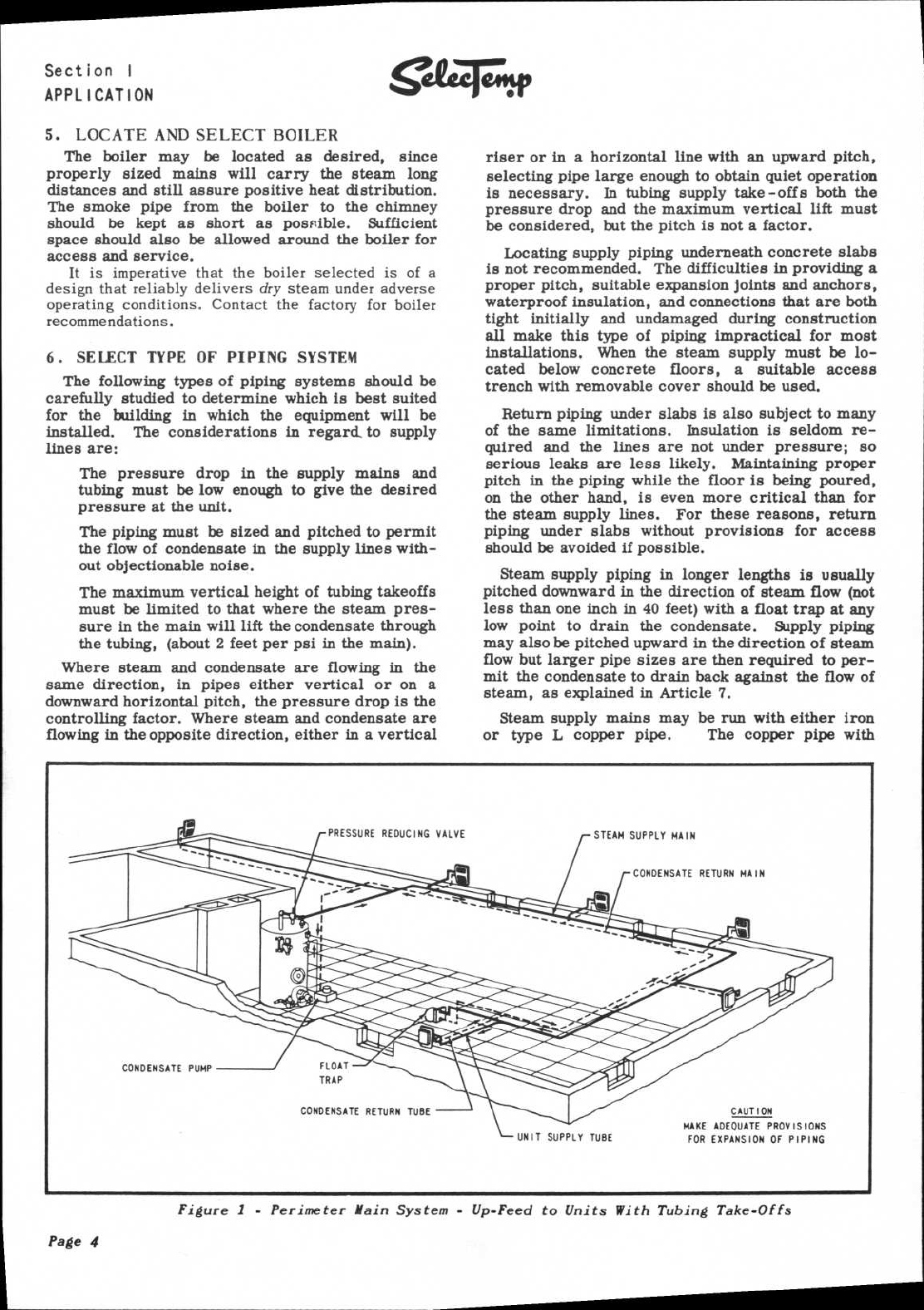
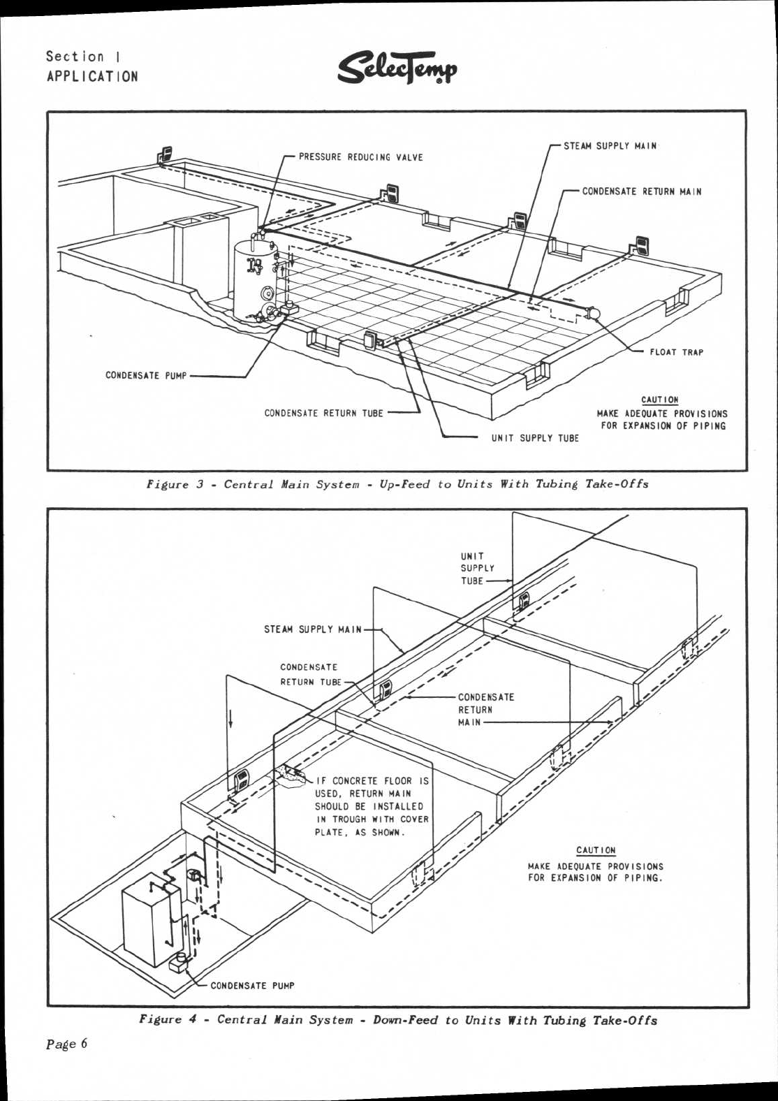
CAUTION
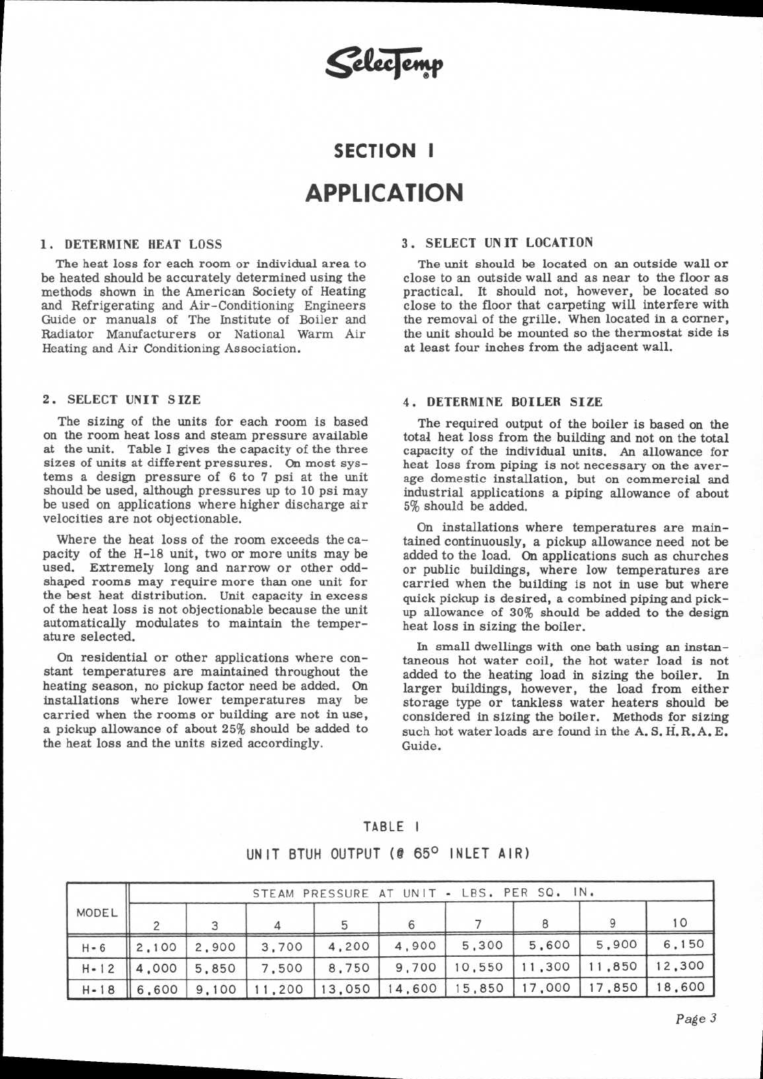
MAKE ADEQUATE PROVISIONS
FOR EXPANSION OF PIPING
CONDENSATE RETURN TUBE
UNIT SUPPLY TUBE
PRESSURE REDUCING VALVE
STEAM SUPPLY MAIN
CONDENSATE RETURN MAIN
CONDENSATE PUMP
FLOAT
TRAP
Section I
APPLICATION
Sualz.tx
5.
LOCATE AND SELECT BOILER
The boiler may be located as desired, since
properly sized mains will carry the steam long
distances and still assure positive heat distribution.
The smoke pipe from the boiler to the chimney
should be kept as short as possible. Sufficient
space should also be allowed around the boiler for
access and service.
It
is imperative that the boiler selected is of a
design that reliably delivers
dry
steam under adverse
operating conditions. Contact the factory for boiler
recommendations.
6.
SELECT TYPE OF PIPING SYSTEM
The following types of piping systems should be
carefully studied to determine which is best suited
for the building in which the equipment will be
installed. The considerations in regard, to supply
lines are:
The pressure drop in the supply mains and
tubing must be low enough to give the desired
pressure at the unit.
The piping must be sized and pitched to permit
the flow of condensate in the supply lines with-
out objectionable noise.
The maximum vertical height of tubing takeoffs
must be limited to that where the steam pres-
sure in the main will lift the condensate through
the tubing, (about 2 feet per psi in the main).
Where steam and condensate are flowing in the
same direction, in pipes either vertical or on a
downward horizontal pitch, the pressure drop is the
controlling factor. Where steam and condensate are
flowing in the opposite direction, either in a vertical
riser or in a horizontal line with an upward pitch,
selecting pipe large enough to obtain quiet operation
is necessary. In tubing supply take -offs both the
pressure drop and the maximum vertical lift must
be considered, but the pitch is not a factor.
Locating supply piping underneath concrete slabs
is not recommended. The difficulties in providing a
proper pitch, suitable expansion joints and anchors,
waterproof insulation, and connections that are both
tight initially and undamaged during construction
all make this type of piping impractical for most
installations. When the steam supply must be lo-
cated below concrete floors, a suitable access
trench with removable cover should be used.
Return piping under slabs is also subject to many
of the same limitations. Insulation is seldom re-
quired and the lines are not under pressure; so
serious leaks are less likely. Maintaining proper
pitch in the piping while the floor is being poured,
on the other hand, is even more critical than for
the steam supply lines. For these reasons, return
piping under slabs without provisions for access
should be avoided if possible.
Steam supply piping in longer lengths is usually
pitched downward in the direction of steam flow (not
less than one inch in 40 feet) with a float trap at any
low point to drain the condensate. Supply piping
may also be pitched upward in the direction of steam
flow but larger pipe sizes are then required to per-
mit the condensate to drain back against the flow of
steam, as explained in Article 7.
Steam supply mains may be run with either iron
or type L copper pipe.
The copper pipe with
Figure 1 - Perimeter Main System - Up-Feed to Units With Tubing Take-Offs
Page
4