9
Use and Maintenance:
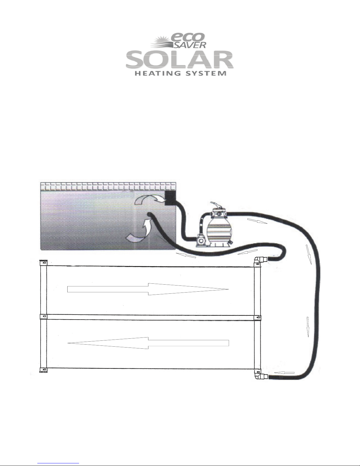
1. Once installed, your ecoSAVER Solar Heating System is easy to use. Simply turn the filter system on and
your system is working.
2. Place your hand in the water in front of the pool inlet fitting. You should feel a reasonable flow of water
returning to the pool. If you do not, you may need to check the size of the pool pump. You may also need
to check that only one Water Baffle has been installed in the system.
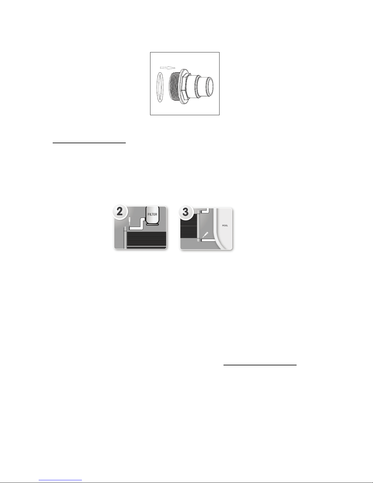
3. The filter should be run at least 6 hour a day during the sunniest and hottest part of the day for maximum
heat gain to occur.
4. When the system is running the small tubes of the panel will feel cool to the touch as the water passing
through the tubes absorbs the warmth of the sun. If the sun is shining and the system is not running the
panels will be hot to the touch.
5. If the pool filter is run on cool cloudy days or at night it is recommended that an optional Diverter Valve
(Part # ESDV-1) be used to allow water to by pass the small tubes of the solar panel. Running water
through the panels at these times will cool the water.
6. It is strongly recommended that a solar blanket and reel system be used for optimal results. Failure to
properly use a solar blanket will diminish temperature retention, especially at night. Please cover the pool
at night and when not in use
Winterizing the ecoSAVER System:
1. Your ecoSAVER solar panels must be drained for the winter if temperatures in your region drop below
32 º F at any time. THE WARRANTY DOES NOT COVER DAMAGE FROM FREEZING WATER.
2. For an above ground pool with a ground-mounted solar panel, winterize the pool per the manufacturer’s
instructions. Remove the hoses to the panel. Drain the panel and store it in a warm place for the winter.
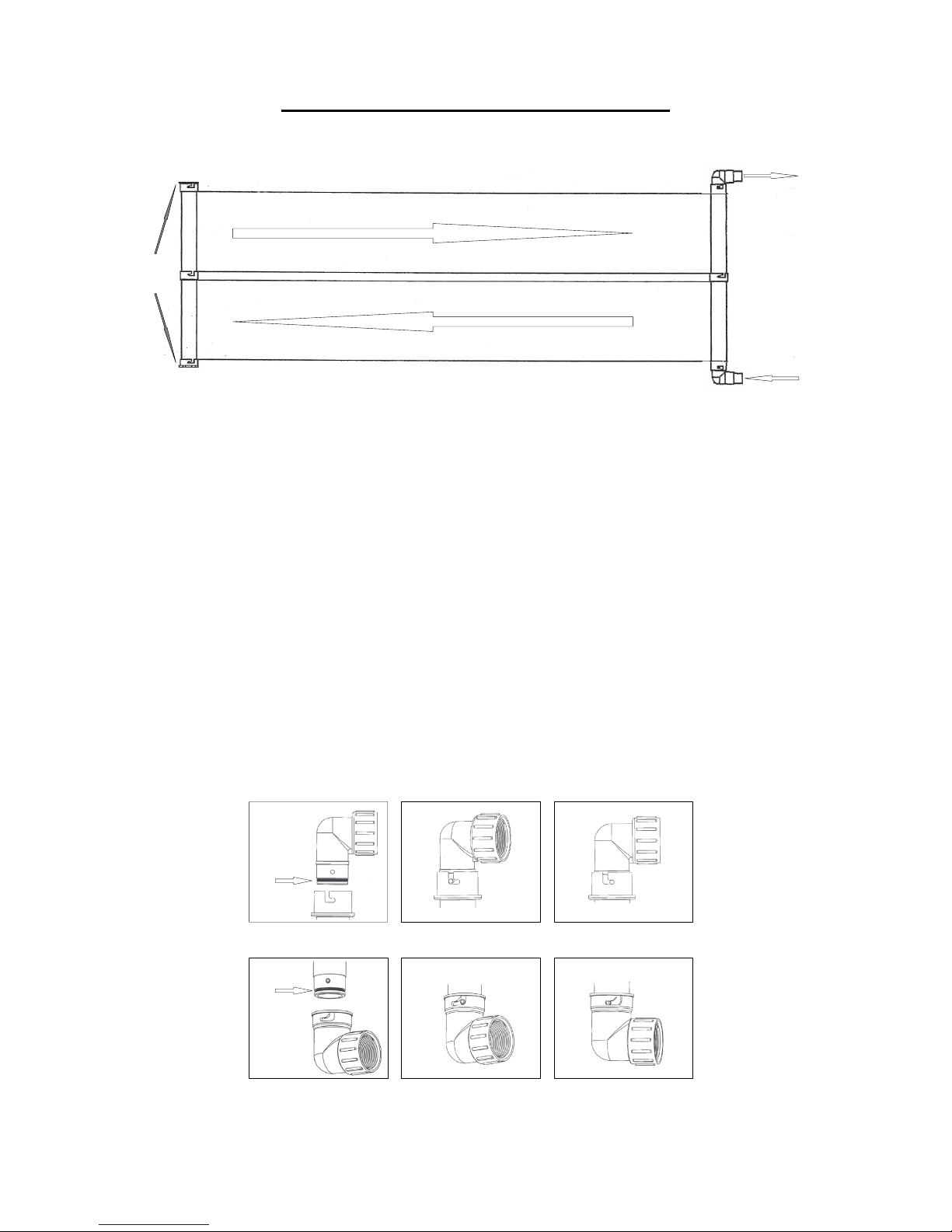
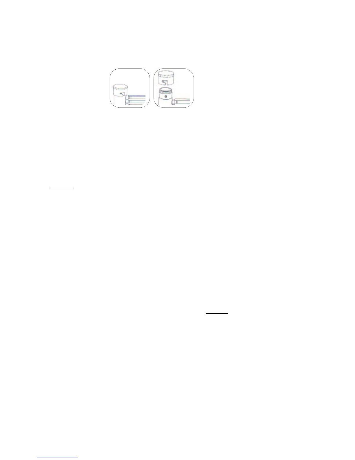
3. For a rack, roof or In Ground pool installation, remove the 2 Twist-Connect Elbows and allow the water to
drain. This may take ½ hour as the tubes are small and drain slowly. Blow out the panel in the same way
you blow out plumbing lines. If you are still uncertain that all the tubes are fully drained, lift the panels at
one end to allow any remaining water to drain.
4. The ecoSAVER panels are designed to withstand winter temperatures and once fully drained, may be left
outside on a roof or rack. However, it is recommended that the panels be stored inside during the winter
in areas subject to freezing temperatures. The Twist-Connect Elbows were specifically designed to allow
easy installation and removal of the panels