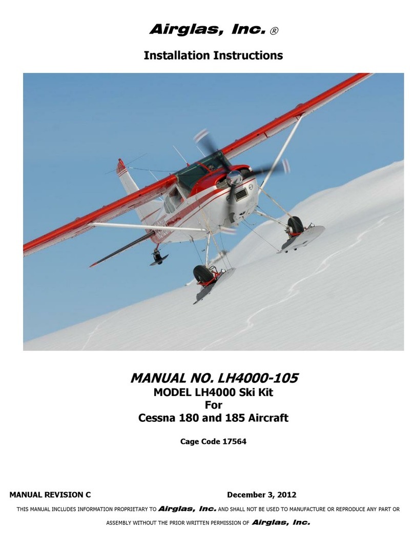
Airglas LH4000 Main Ski Manual

MANUAL REVISION B December 3, 2012
THIS MANUAL INCLUDES INFORMATION PROPRIETARY TO
Airglas, Inc.
AND SHALL NOT BE USED TO MANUFACTURE OR REPRODUCE ANY PART OR
ASSEMBLY WITHOUT THE PRIOR WRITTEN PERMISSION OF
Airglas, Inc.
Airglas, Inc. ®
Instructions for Continued Airworthiness
Including
Maintenance and Service Instructions
MANUAL NO. LH4000-106
MODEL LH4000 Ski Kit
For
Cessna 180 and 185 Aircraft
Cage Code 17564

Airglas, Inc.
Manual # LH4000-106
2 | P a g e
MANUAL REVISION B December 3, 2012
THIS MANUAL INCLUDES INFORMATION PROPRIETARY TO
Airglas, Inc.
AND SHALL NOT BE USED TO MANUFACTURE OR REPRODUCE ANY PART OR
ASSEMBLY WITHOUT THE PRIOR WRITTEN PERMISSION OF
Airglas, Inc.
This Page Intentionally Left Blank

Airglas, Inc.
Manual # LH4000-106
3 | P a g e
MANUAL REVISION B December 3, 2012
THIS MANUAL INCLUDES INFORMATION PROPRIETARY TO
Airglas, Inc.
AND SHALL NOT BE USED TO MANUFACTURE OR REPRODUCE ANY PART OR
ASSEMBLY WITHOUT THE PRIOR WRITTEN PERMISSION OF
Airglas, Inc.
Record of Revision
Distribution of Changes
A new copy of the revised manual or affected pages will be maintained on the
Airglas,
Inc.
website.
REV
LEVEL
REV DATE
Affected
Pages
BY
EXPLANATION OF REVISION
Initial
Release
25 Jan 2005
-
Original Document
A
August 21,
2012
ALL
Clifford D. Belleau
Added alternate hydraulic cylinder. Revised rigging
instructions.
B
December 3,
2012
7, 9, 11
Clifford D. Belleau
Changed rigging bracket attach drill bit size to #10. Corrected
axle to landing gear nut part numbers.

Airglas, Inc.
Manual # LH4000-106
4 | P a g e
MANUAL REVISION B December 3, 2012
THIS MANUAL INCLUDES INFORMATION PROPRIETARY TO
Airglas, Inc.
AND SHALL NOT BE USED TO MANUFACTURE OR REPRODUCE ANY PART OR
ASSEMBLY WITHOUT THE PRIOR WRITTEN PERMISSION OF
Airglas, Inc.
Airworthiness Limitations
"The Airworthiness Limitations section is FAA approved and specifies maintenance required under Sections
43.16 and 91.403 of the Federal Aviation Regulations unless an alternative program has been FAA approved."
Limitations:
Currently there are no components of the LH4000 Wheel Ski Kit that have a time limited mandatory
service interval.

Airglas, Inc.
Manual # LH4000-106
5 | P a g e
MANUAL REVISION B December 3, 2012
THIS MANUAL INCLUDES INFORMATION PROPRIETARY TO
Airglas, Inc.
AND SHALL NOT BE USED TO MANUFACTURE OR REPRODUCE ANY PART OR
ASSEMBLY WITHOUT THE PRIOR WRITTEN PERMISSION OF
Airglas, Inc.
Table of Contents
Page
1.0 Introduction and Description 6-15
2.0 Placards and Markings 16
3.0 Removal 17
4.0 Re-installation 17-18
5.0 Control and Operation 18-19
6.0 Servicing Information 19-20
7.0 Instructions for Continued Airworthiness 20-21
8.0 Specifications 22
9.0 Trouble Shooting 23
10.0 Drawings and Diagrams 24

Airglas, Inc.
Manual # LH4000-106
6 | P a g e
MANUAL REVISION B December 3, 2012
THIS MANUAL INCLUDES INFORMATION PROPRIETARY TO
Airglas, Inc.
AND SHALL NOT BE USED TO MANUFACTURE OR REPRODUCE ANY PART OR
ASSEMBLY WITHOUT THE PRIOR WRITTEN PERMISSION OF
Airglas, Inc.
1.0 INTRODUCTION AND DESCRIPTION
Introduction: Since1955
Airglas, Inc.
has designed and manufactured a full line of composite
skis that dramatically increase the usefulness of the aircraft by allowing it to operate on snow or
frozen surfaces. The installation of the LH4000 hydraulic wheel ski kit allows the aircraft to operate
on paved or hard surfaces, and snow. The skis are actuated by a hydraulic cylinder on each ski with
an electric/hydraulic or hand pump to provide operating pressure. The ski is pushed down as a sliding
door closes the opening in the ski and causes the tire to ride up on top of the door. The door closes
off the wheel opening, thus creating the performance characteristics of a “straight ski”. When the
airplane is on snow, deploying to the ski position dramatically improves the takeoff performance
(compared to wheel penetration skis). The simplicity of this design allows for a low maintenance high
performance ski kit.
Description: The LH4000 ski kit consists of essentially 4 systems;
1. The Mechanical System –This includes the ski with all attaching hardware (interface to the
gear leg) and the rigging components.
2. The Hydraulic System –This includes hydraulic lines (both onboard and external), hydraulic
actuating cylinders (on the skis), all the hydraulic fittings on the skis, and the hydraulic pump.
3. The Electrical System –This includes pressure switches, a circuit breaker, wiring, a control
switch and indicator lights (the electric pump is covered under the hydraulic system).
4. Placards and Markings- This includes the flight manual supplement, placards, and instrument
markings.
Instructions for initial installation of this kit are detailed within manual LH4000-105.
Notes:
1.
All hardware in this kit shall be installed and torqued IAW AC 43.13-1B Chapter 7, Par 7-40,
Table 7-1 and table 7-2, unless otherwise specified.
2. Aircraft must be equipped with 8.50x6 main tires for ski operations.
1.1 SKI RIGGING BRACKETS AND ATTACH FITTINGS
The aircraft must have the brackets and attach fittings installed on the fuselage for the rigging to
attach.

Airglas, Inc.
Manual # LH4000-106
7 | P a g e
MANUAL REVISION B December 3, 2012
THIS MANUAL INCLUDES INFORMATION PROPRIETARY TO
Airglas, Inc.
AND SHALL NOT BE USED TO MANUFACTURE OR REPRODUCE ANY PART OR
ASSEMBLY WITHOUT THE PRIOR WRITTEN PERMISSION OF
Airglas, Inc.
1.1 SKI RIGGING BRACKETS AND ATTACH FITTINGS- CONTINUED
Rigging Bracket Installations
Figure 1

Airglas, Inc.
Manual # LH4000-106
8 | P a g e
MANUAL REVISION B December 3, 2012
THIS MANUAL INCLUDES INFORMATION PROPRIETARY TO
Airglas, Inc.
AND SHALL NOT BE USED TO MANUFACTURE OR REPRODUCE ANY PART OR
ASSEMBLY WITHOUT THE PRIOR WRITTEN PERMISSION OF
Airglas, Inc.
Left Forward Rigging Bracket Installation (LW3600-180A-10 Opposite)
(See Drawing LW3600-180A-9 & LH3600-17 INST. for 180 thru 180F)
Figure 2
1.1 SKI RIGGING BRACKETS AND ATTACH FITTINGS-CONTINUED
LW3600-180A-9 Forward Rigging Bracket Installed (LW3600-180A-10 is opposite)
Photo 1

Airglas, Inc.
Manual # LH4000-106
9 | P a g e
MANUAL REVISION B December 3, 2012
THIS MANUAL INCLUDES INFORMATION PROPRIETARY TO
Airglas, Inc.
AND SHALL NOT BE USED TO MANUFACTURE OR REPRODUCE ANY PART OR
ASSEMBLY WITHOUT THE PRIOR WRITTEN PERMISSION OF
Airglas, Inc.
1.1 SKI RIGGING BRACKETS AND ATTACH FITTINGS-CONTINUED
DRILL #10 AND INSTALL
CR3213-6-4 BLIND RIVET.
LH3600-17
AN3-5A BOLT
LH3600-17-1
DOUBLER
STA 65.33
BULKHEAD
(REF.)
MS21044N3 NUT
NAS1149F0363P WASHER
A-A A
A
LEFT HAND SHOWN
RIGHT HAND OPPOSITE
INSTALL DOUBLER UNDER FORWARD
BOLTS, TRIM AS REQUIRED.
A/C SIDE SKIN
DRILL (5) EXISTING RIVETS,
REAM (4) WITH #10 DRILL BIT.
ALIGN LH3600-17 FOR BEST
EDGE DISTANCE. BACK DRILL
LH3600-17.
LH3600-17 Rear Rigging Bracket Installation (Left Hand Shown- Right Opposite)
Figure 3

Airglas, Inc.
Manual # LH4000-106
10 | P a g e
MANUAL REVISION B December 3, 2012
THIS MANUAL INCLUDES INFORMATION PROPRIETARY TO
Airglas, Inc.
AND SHALL NOT BE USED TO MANUFACTURE OR REPRODUCE ANY PART OR
ASSEMBLY WITHOUT THE PRIOR WRITTEN PERMISSION OF
Airglas, Inc.
Rear Rigging Bracket Installation LH3600-17 (LH3600-18 Opposite)
Photo 2
1.1 SKI RIGGING BRACKETS AND ATTACH FITTINGS-CONTINUED
Rear Rigging Bracket Doubler Installation LH3600-17-1 (LH3600-18-1 Opposite)
Photo 3

Airglas, Inc.
Manual # LH4000-106
11 | P a g e
MANUAL REVISION B December 3, 2012
THIS MANUAL INCLUDES INFORMATION PROPRIETARY TO
Airglas, Inc.
AND SHALL NOT BE USED TO MANUFACTURE OR REPRODUCE ANY PART OR
ASSEMBLY WITHOUT THE PRIOR WRITTEN PERMISSION OF
Airglas, Inc.
Front Safety Cable Bracket Installation
Figure 4
1.1 OUTBOARD AND INBOARD STUB INSTALLATION
Stub Axle Breakdown

Airglas, Inc.
Manual # LH4000-106
12 | P a g e
MANUAL REVISION B December 3, 2012
THIS MANUAL INCLUDES INFORMATION PROPRIETARY TO
Airglas, Inc.
AND SHALL NOT BE USED TO MANUFACTURE OR REPRODUCE ANY PART OR
ASSEMBLY WITHOUT THE PRIOR WRITTEN PERMISSION OF
Airglas, Inc.
Figure 5
Inboard Stub Axle Installation-Figure 6
Note: It is suggested that the aircraft wheel alignment is confirmed using Cessna service
instructions prior to installation of the skis.
1.2 HYDRAULIC INSTALLATION-FUSELAGE

Airglas, Inc.
Manual # LH4000-106
13 | P a g e
MANUAL REVISION B December 3, 2012
THIS MANUAL INCLUDES INFORMATION PROPRIETARY TO
Airglas, Inc.
AND SHALL NOT BE USED TO MANUFACTURE OR REPRODUCE ANY PART OR
ASSEMBLY WITHOUT THE PRIOR WRITTEN PERMISSION OF
Airglas, Inc.
Electric Pump Mounting -Photo 5
Optional Hand Pump Mounting - Photo 6
1.2 HYDRAULIC INSTALLATION-FUSELAGE-CONTINUED

Airglas, Inc.
Manual # LH4000-106
14 | P a g e
MANUAL REVISION B December 3, 2012
THIS MANUAL INCLUDES INFORMATION PROPRIETARY TO
Airglas, Inc.
AND SHALL NOT BE USED TO MANUFACTURE OR REPRODUCE ANY PART OR
ASSEMBLY WITHOUT THE PRIOR WRITTEN PERMISSION OF
Airglas, Inc.
Hydraulic Schematic –Figure 7
NOTE:
The optional hand pump installation location may vary from aircraft to aircraft.
1.2 HYDRAULIC INSTALLATION-EXTERNAL

Airglas, Inc.
Manual # LH4000-106
15 | P a g e
MANUAL REVISION B December 3, 2012
THIS MANUAL INCLUDES INFORMATION PROPRIETARY TO
Airglas, Inc.
AND SHALL NOT BE USED TO MANUFACTURE OR REPRODUCE ANY PART OR
ASSEMBLY WITHOUT THE PRIOR WRITTEN PERMISSION OF
Airglas, Inc.
Additional Clamp Installation-Photo 7
1.3 ELECTRICAL INSTALLATION
Ski Pump Switch Installation-Photo 8

Airglas, Inc.
Manual # LH4000-106
16 | P a g e
MANUAL REVISION B December 3, 2012
THIS MANUAL INCLUDES INFORMATION PROPRIETARY TO
Airglas, Inc.
AND SHALL NOT BE USED TO MANUFACTURE OR REPRODUCE ANY PART OR
ASSEMBLY WITHOUT THE PRIOR WRITTEN PERMISSION OF
Airglas, Inc.
1.3 ELECTRICAL INSTALLATION-CONTINUED
Ski Pump Electrical Schematic-Figure 8
Note: Wiring instructions for the Parker-Electro/Hydraulic pump.
1. Make sure that the polarity for the pump is correct.
BLUE 12 V or Black 24V (SKIS) GREEN 12V or Orange 24 V (WHEELS)
a. Switch sends power to blue or black wire during “Ski” selection.
This will pressurize the “UP” port of the pump.
b. Switch sends power to the green or orange wire when “Wheels” are selected.
This will pressurize the “DOWN” side of the pump.
c. Make sure the “UP” Port on the pump goes to the FWD fitting on the ski actuator
cylinder.
2. When arranging the switch and indicator lights on the control panel, make sure that the
switch “UP” position is for Skis (Yellow Lights) and switch “DOWN” is for Wheels (green
lights).
NOT following these instructions WILL make the system OPERATE INCORRECTLY.
2.0 PLACARDS AND MARKINGS

Airglas, Inc.
Manual # LH4000-106
17 | P a g e
MANUAL REVISION B December 3, 2012
THIS MANUAL INCLUDES INFORMATION PROPRIETARY TO
Airglas, Inc.
AND SHALL NOT BE USED TO MANUFACTURE OR REPRODUCE ANY PART OR
ASSEMBLY WITHOUT THE PRIOR WRITTEN PERMISSION OF
Airglas, Inc.
PLACARDS
The following information must be displayed in the form of composite or individual placards in
addition to those specified in the aircraft basic handbook.
Place Airspeed Restriction Placard on instrument
panel immediately adjacent to Airspeed Indicator
and in full view of pilot.
AVOID SLIPS WITH FLAPS EXTENDED WHEN
AIRGLAS LH4000 SKIS ARE INSTALLED
Place placard on instrument panel in full view of pilot.
DO NOT EXTEND OR RETRACT SKIS AT SPEEDS ABOVE 125
KNOTS
DO NOT EXTEND OR RETRACT SKIS WHILE IN MOTION ON
THE GROUND
Place placard on instrument panel in full view of pilot.
IN FLOATPLANE, AMPHIBIAN AND SKIPLANES EQUIPED WITH
AIRGLAS LH4000 RETRACT FLAPS TO 20° IMMEDIATELY AFTER
APPLYING POWER FOR BALKED LANDING GO-AROUND
Place placard on instrument panel in full view of pilot.
DO NOT LAND ON SNOW WITH TIRES DOWN WHEN AIRGLAS LH4000
SKIS ARE INSTALLED
Place placard on instrument panel in full view of pilot.
3.0 SKI REMOVAL
DO NOT EXCEED 150 KIAS
WITH AIRGLAS LH4000 SKIS INSTALLED

Airglas, Inc.
Manual # LH4000-106
18 | P a g e
MANUAL REVISION B December 3, 2012
THIS MANUAL INCLUDES INFORMATION PROPRIETARY TO
Airglas, Inc.
AND SHALL NOT BE USED TO MANUFACTURE OR REPRODUCE ANY PART OR
ASSEMBLY WITHOUT THE PRIOR WRITTEN PERMISSION OF
Airglas, Inc.
1. Retract the skis (tires down)
2. Pull the ski pump circuit breaker and remove the ski indicator light circuit inline fuse. Secure
the pump circuit breaker with a ty-wrap to prevent accidental activation. Placard the ski pump
breaker and the ski selector switch “Disabled”.
3. Remove the rear check cables and the forward safety cables from the fuselage by removing
the AN395-17 clevis pins. Retain the pins for future use.
4. Disconnect the ski hydraulic hoses from the fuselage at the bulkhead fittings. Cap the fittings
and plug the hoses with AN929 and AN806 caps and plugs respectively. Install two ty-wraps
around one of the fitting and hose pairs on each side to reduce the re-installation time.
Remove the ski hydraulic hoses from the landing gear.
5. Hoist or jack the aircraft to attain clearance enough to allow the bungee assembly’s to slacken,
and remove the bungee assembly’s from the aircraft by removing the AN395-17 clevis pins. (If
there is no lift available: use a bungee stretcher to slacken the cable, remove the tail wheel
assembly’s and roll the aircraft back off the skis. Reinstall tail wheels after the skis are
removed.)
6. Remove the bolts securing the yoke to the inboard flange and outboard stub axle. Repeat for
the other ski. Secure the AN960-1216 washers to the yoke in the order of their removal.
7. Remove the LH3600-10 yoke restraining cable form the LH3600-7 stub axle by removing the
AN3 bolt. Retain the bolt for future use.
8. Remove the skis from under the aircraft and lower the aircraft to the ground.
9. Ensure that the aircraft weight and balance reflect the removal of the skis.
10.Make an entry in the aircraft maintenance records recording the removal of the skis.
4.0 SKI RE-INSTALLATION
1. Hoist or jack the aircraft. (If there is no lift available, remove the tail wheel assembly’s and roll
the aircraft on the skis. Reinstall tail wheels after the skis are installed. Use a bungee stretcher
to install the bungee cable assembly.)
2. Install new nylon set screws in the stub axle and inboard flange. Install the screws so that
they are just flush with the minor diameter of the threads of the stub and flange.
3. Slide the skis under the aircraft and install the LH3600-10 yoke restraining cable on each
LH3600-6 stub axle. Align the LH3600-5 yoke with the LH3600-7 stub axle and LH3600-6
inboard flange. Re-install the AN960-1216 washers in the order removed and install the two
NAS1312-5 (or AN12-17A alternate) bolts. Torque the NAS1312-5 (or AN12-17A alternate)
bolts to 70 ft. lbs. Repeat for the other ski.
4. With the ski retracted (tires down), confirm the skis are parallel with the fuselage centerline.
5. Hoist the aircraft high enough to install the LH3600-14 bungee cable assy. and the LH3600-15
safety cable assy. If there is not enough lift available to allow the cable to be installed, the
bungee must be stretched using a mechanical bungee tool. Use caution when stretching the
4.0 SKI RE-INSTALLATION-CONTINUED

Airglas, Inc.
Manual # LH4000-106
19 | P a g e
MANUAL REVISION B December 3, 2012
THIS MANUAL INCLUDES INFORMATION PROPRIETARY TO
Airglas, Inc.
AND SHALL NOT BE USED TO MANUFACTURE OR REPRODUCE ANY PART OR
ASSEMBLY WITHOUT THE PRIOR WRITTEN PERMISSION OF
Airglas, Inc.
bungee. Ensure the bungee has at least one full twist when installed. Repeat for the other ski.
6. Lower the aircraft to the ground and install the LH3600-13 rear check cables.
7. Install the hydraulic hoses at the fuselage. Secure the hoses to the landing gear using the clips
and ty-wraps.
8. Remove the ty-wrap from the ski pump circuit breaker and reinstall the fuse to the ski
indicator lights. Remove the “disabled” placards.
9. Service the ski pump reservoir with MIL-H-5606 or equivalent fluid.
10.Hoist the aircraft and raise the tail of the aircraft until it is in the level flight attitude with the
tires retracted (skis deployed).
11.Confirm the skis are installed with a +1.5° tip up in the ski position in level flight attitude.
12.Confirm that the tension on the bungee cable is at least 80 lbs. Ensure the bungee has at least
one full twist when installed.
13.Make sure all hardware is installed, torqued, and cotter pinned as necessary.
14.Cycle the skis to remove any entrapped air. (fill the reservoir with the ski retracted, tires
protruding)
15.Lower the aircraft to the ground and ensure the skis will cycle. Confirm the indicator lights
work correctly.
16.Confirm the aircraft weight and balance and equipment list reflect the ski installation.
17.Confirm the Skiplane Model 180/185 Approved Flight Manual Supplement is in the aircraft
flight manual.
18.Confirm the placards and markings called out in the Skiplane Model 180/185 Approved Flight
Manual Supplement are correctly located in the aircraft.
19.Record installation of the skis in the aircraft maintenance records.
5.0 CONTROL AND OPERATION
Control and Operation Information: The door for the LH4000 Ski Kit is actuated by the
electric/hydraulic pump (preferred) or a manually operated hand pump in the cockpit. The
electric/hydraulic pump is controlled via a 3 position toggle switch and indicator lights that are
located on the instrument panel.
1. When the switch is lifted up, the cylinder will extend and slide the door under the tire. While
the switch is held up an operation indicator yellow light will illuminate showing the ski position
is selected and the pump is cycling. When the cycle is complete, a second (Skis Locked) yellow
light will illuminate and stay on to confirm full deployment of the skis. As the switch is released
the operation light will extinguish, but the position locked light will remain lit as long as the
skis are extended.
2. When the switch is pressed down, the door will retract and expose the tire. While the switch is
held down an operation indicator green light will illuminate showing the wheel position is
5.0 CONTROL AND OPERATION-CONTINUED

Airglas, Inc.
Manual # LH4000-106
20 | P a g e
MANUAL REVISION B December 3, 2012
THIS MANUAL INCLUDES INFORMATION PROPRIETARY TO
Airglas, Inc.
AND SHALL NOT BE USED TO MANUFACTURE OR REPRODUCE ANY PART OR
ASSEMBLY WITHOUT THE PRIOR WRITTEN PERMISSION OF
Airglas, Inc.
selected. When the cycle is complete, a second (Wheels Locked) green light will illuminate and
stay on to confirm retraction of the skis. When the switch is released the selector light will
extinguish, but the position locked light will remain lit as long as the skis are retracted.
6.0 SERVICING INFORMATION
Mechanical System –The skis themselves are virtually maintenance free with the top of the
ski constructed of a thermal plastic composite and the bottom of the ski is Ultra High Molecular
Weight Poly-ethylene (UHMW). The ski bottom has two runners that run the forward length of
the ski and are made out of ¼” UHMW. Replaceable stainless steel runners are provided at
the aft end of the ski. The runners are designed to give tracking stability to the ski and protect
the bottom of the ski. When the runners have worn to a thickness of less than .125”, they will
need to be replaced. Waxing the ski bottoms for decreased friction and improved glide is
recommended, especially in wet snow.
The Yoke Assembly (LH3600-5), and Retaining Rod (LH3600-5-5) need to be checked for
security and proper lubrication. Yoke pivots require light greasing (with any multipurpose
heavy duty wheel bearing grease) every 25 hours and the rod ends will need light oiling (with
LPS-2 or equivalent low viscosity oil) every 25 hours. The yoke is made out 4130 Chromalloy
steel and is heat treated after welding (no field repairs are allowed). The (LH3600-10) Yoke
Safety Restraining Cable system is designed to keep the yoke from traveling over-center in the
unlikely event of a rigging failure.
The Tail Wheel Bracket Kit (LH3600A-12) is made of stainless steel angled brackets with 6”
aluminum wheels with a solid urethane tires. The cartridge wheel bearings cannot be serviced
and should be replaced when worn. When the tire is worn to a thickness of less than .25” the
wheel should be replaced.
The rigging is made up of galvanized steel 5/32 cable for the ice cutter, safety cable, and
natural rubber 8020CW cold weather bungee rings for the front assembly and 5/32 cables for
the check cable assembly. The bungees should be kept out of direct sunlight and must not
come in contact with fuel or other chemicals. Any fraying of the sheathing should be noted
and inspected for rubber strand damage or degradation. Swaged ends and cables should be
inspected for fraying and slippage. Hardware should be inspected for security.
Hydraulic System –The hydraulic system supplied with the skis uses an Electric/Hydraulic
Pump, (a hand pump is optional but not offered through Airglas, Inc.) to pump fluid to a
hydraulic actuating cylinder mounted on the ski. The Electric/Hydraulic Pump is intended to be
mounted behind the cabin area aft of station 108. Hydraulic lines are routed through the
aircraft under the floor and out to the gear legs. The air is bled from the hydraulic system by
6.0 SERVICING INFORMATION-CONTINUED
Other manuals for LH4000 Main Ski
1
Table of contents
Other Airglas Toy manuals
Popular Toy manuals by other brands

Eduard
Eduard 36 114 manual

Globo
Globo SPIDKO Moto Racing User manual & assembly instructions

M.T.H.
M.T.H. E-8 DIESEL ENGINE Operating instrutions

Fly Wing
Fly Wing FW450L quick start guide

Zapf Creation
Zapf Creation BABY born Sister Styling Head manual

miniature aircraft
miniature aircraft X-cell Spectra-G 125-100c Operator's guide

roco
roco 76438 manual

Eduard
Eduard MiG-17 wheels Assembly instructions

Fisher-Price
Fisher-Price Y6599 quick start guide

Oregon Scientific
Oregon Scientific 17015 user guide

MGA Entertainment
MGA Entertainment POOPSIE CUTIE TOOTIES SURPRISE 557036 quick start guide

ROBBE
ROBBE Edge 540 ARF Assembly and operating instructions