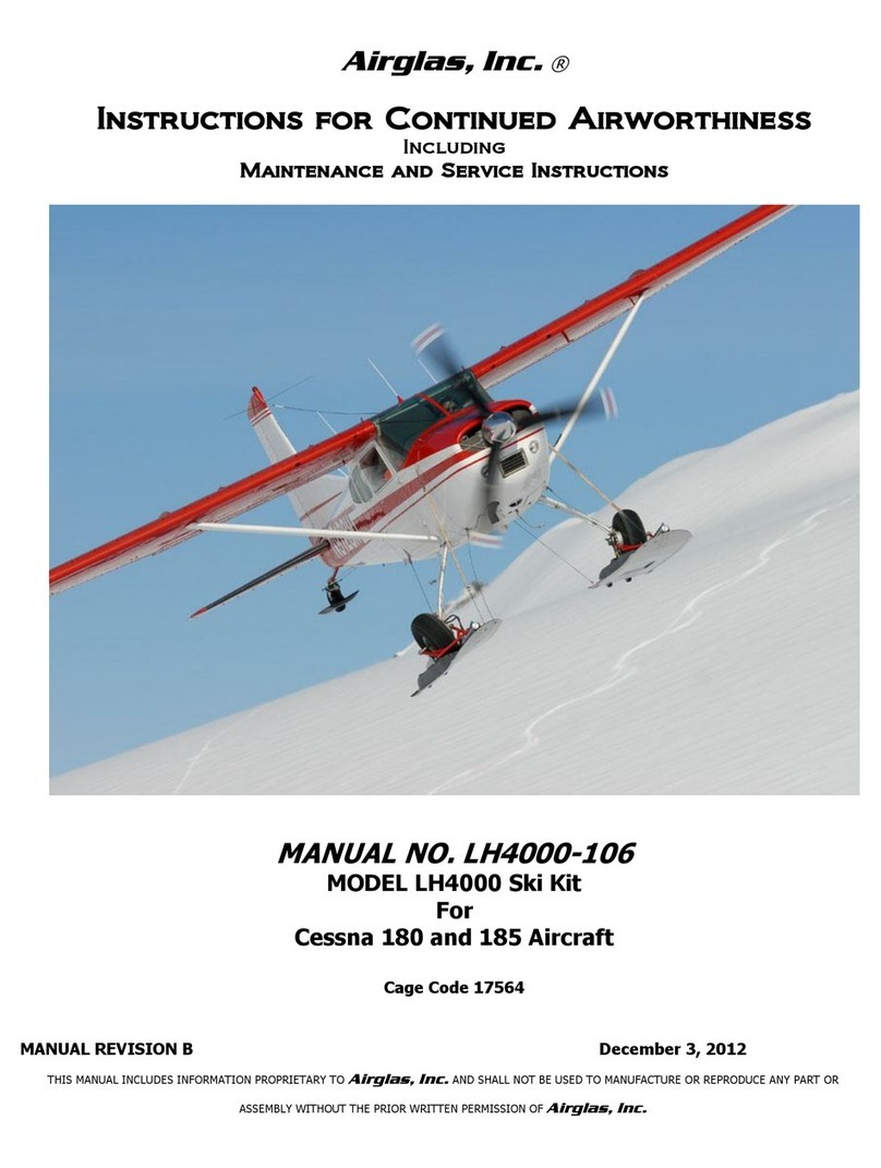
Airglas LH4000 Main Ski User manual

MANUAL REVISION C December 3, 2012
THIS MANUAL INCLUDES INFORMATION PROPRIETARY TO
Airglas, Inc.
AND SHALL NOT BE USED TO MANUFACTURE OR REPRODUCE ANY PART OR
ASSEMBLY WITHOUT THE PRIOR WRITTEN PERMISSION OF
Airglas, Inc.
Airglas, Inc. ®
Installation Instructions
MANUAL NO. LH4000-105
MODEL LH4000 Ski Kit
For
Cessna 180 and 185 Aircraft
Cage Code 17564

Airglas, Inc.
Manual # LH4000-105
2 | P a g e
MANUAL REVISION C December 3, 2012
THIS MANUAL INCLUDES INFORMATION PROPRIETARY TO
Airglas, Inc.
AND SHALL NOT BE USED TO MANUFACTURE OR REPRODUCE ANY PART OR
ASSEMBLY WITHOUT THE PRIOR WRITTEN PERMISSION OF
Airglas, Inc.
This Page Intentionally Left Blank

Airglas, Inc.
Manual # LH4000-105
3 | P a g e
MANUAL REVISION C December 3, 2012
THIS MANUAL INCLUDES INFORMATION PROPRIETARY TO
Airglas, Inc.
AND SHALL NOT BE USED TO MANUFACTURE OR REPRODUCE ANY PART OR
ASSEMBLY WITHOUT THE PRIOR WRITTEN PERMISSION OF
Airglas, Inc.
Record of Revision
Distribution of Changes
A new copy of the revised manual or affected pages will be maintained on the
Airglas,
Inc.
website.
REV
LEVEL
REV DATE
Affected
Pages
BY
EXPLANATION OF REVISION
Initial
Release
25 Jan 2005
-
Original Document
A
July 11,
2005
1, 3, 8, 14,
16, 28, 29,
37
B
August 20,
2012
ALL
Clifford D. Belleau
Added alternate hydraulic cylinder. Revised rigging
instructions.
C
December 3,
2012
7, 8, 10, 11,
17, 18, 19,
20
Clifford D. Belleau
Changed rigging bracket attach drill bit size to #10. Added
note to section 3.1. Corrected axle to landing gear nut part
numbers. Added Reference to Figure 6.

Airglas, Inc.
Manual # LH4000-105
4 | P a g e
MANUAL REVISION C December 3, 2012
THIS MANUAL INCLUDES INFORMATION PROPRIETARY TO
Airglas, Inc.
AND SHALL NOT BE USED TO MANUFACTURE OR REPRODUCE ANY PART OR
ASSEMBLY WITHOUT THE PRIOR WRITTEN PERMISSION OF
Airglas, Inc.
Table of Contents
Page
1.0 Introduction and Description 5
2.0 Placards and Markings 6
3.0 Initial Installation 7-23
3.1 Ski Rigging Bracket Installations 7-12
3.2 Hydraulic Installation-Fuselage 12-16
3.3 Electrical Installation 16-18
3.4 Stub Axle Installations 18-20
3.5 Ski Installation 20-21
3.6 External Hydraulic Installation 21-22
3.7 Ski Rigging Installation 22
3.8 Ski Installation Check-out 23
3.9 Ski Installation-Placards,
Documentation 23
4.0 Specifications 24
5.0 Trouble-shooting 24-25
6.0 Drawings and Diagrams 25

Airglas, Inc.
Manual # LH4000-105
5 | P a g e
MANUAL REVISION C December 3, 2012
THIS MANUAL INCLUDES INFORMATION PROPRIETARY TO
Airglas, Inc.
AND SHALL NOT BE USED TO MANUFACTURE OR REPRODUCE ANY PART OR
ASSEMBLY WITHOUT THE PRIOR WRITTEN PERMISSION OF
Airglas, Inc.
1.0 INTRODUCTION AND DESCRIPTION
Introduction: Since1955
Airglas, Inc.
has designed and manufactured a full line of
composite skis that dramatically increase the usefulness of the aircraft by allowing it to operate on
snow or frozen surfaces. The installation of the LH4000 hydraulic wheel ski kit allows the aircraft to
operate on paved or hard surfaces, and snow. The skis are actuated by a hydraulic cylinder on each
ski with an electric/hydraulic or hand pump to provide operating pressure. The ski is pushed down as
a sliding door closes the opening in the ski and causes the tire to ride up on top of the door. The
door closes off the wheel opening, thus creating the performance characteristics of a “straight ski”.
When the airplane is on snow, deploying to the ski position dramatically improves the takeoff
performance (compared to wheel penetration skis). The simplicity of this design allows for a low
maintenance high performance ski kit.
Description:The LH4000 ski kit consists of essentially 4 systems;
1. The Mechanical System –This includes the ski with all attaching hardware (interface to the
gear leg) and the rigging components.
2. The Hydraulic System –This includes hydraulic lines (both onboard and external), hydraulic
actuating cylinders (on the skis), all the hydraulic fittings on the skis, and the hydraulic pump.
3. The Electrical System –This includes pressure switches, a circuit breaker, wiring, a control
switch and indicator lights (the electric pump is covered under the hydraulic system).
4. Placards and Markings- This includes the flight manual supplement, placards, and instrument
markings.
Control and Operation Information: The door for the LH4000 Ski Kit is actuated by the
electric/hydraulic pump (preferred) or a manually operated hand pump in the cockpit. The
electric/hydraulic pump is controlled via a 3 position toggle switch and indicator lights that are
located on the instrument panel.
1. When the switch is lifted up, the cylinder will extend and slide the door under the tire. While
the switch is held up an operation indicator yellow light will illuminate showing the ski position
has been selected and the pump is cycling. When the cycle is complete, a second (Skis
Locked) yellow light will illuminate and stay on to confirm full deployment of the skis. As the
switch is released the operation light will extinguish, but the position locked light will remain lit
as long as the skis are extended.
2. When the switch is pressed down, the door will retract and expose the tire. While the switch is
held down an operation indicator green light will illuminate showing the wheel position has
been selected. When the cycle is complete, a second (Wheels Locked) green light will
illuminate and stay on to confirm retraction of the skis. When the switch is released the
selector light will extinguish, but the position locked light will remain lit as long as the skis are
retracted.

Airglas, Inc.
Manual # LH4000-105
6 | P a g e
MANUAL REVISION C December 3, 2012
THIS MANUAL INCLUDES INFORMATION PROPRIETARY TO
Airglas, Inc.
AND SHALL NOT BE USED TO MANUFACTURE OR REPRODUCE ANY PART OR
ASSEMBLY WITHOUT THE PRIOR WRITTEN PERMISSION OF
Airglas, Inc.
2.0 PLACARDS AND MARKINGS
PLACARDS
The following information must be displayed in the form of composite or individual placards in
addition to those specified in the aircraft basic handbook.
Place Airspeed Restriction Placard on instrument
panel immediately adjacent to Airspeed Indicator
and in full view of pilot.
AVOID SLIPS WITH FLAPS EXTENDED WHEN
AIRGLAS LH4000 SKIS ARE INSTALLED
Place placard on instrument panel in full view of pilot.
DO NOT EXTEND OR RETRACT SKIS AT SPEEDS ABOVE 125
KNOTS
DO NOT EXTEND OR RETRACT SKIS WHILE IN MOTION ON
THE GROUND
Place placard on instrument panel in full view of pilot.
IN FLOATPLANE, AMPHIBIAN AND SKIPLANES EQUIPED WITH
AIRGLAS LH4000 RETRACT FLAPS TO 20° IMMEDIATELY AFTER
APPLYING POWER FOR BALKED LANDING GO-AROUND
Place placard on instrument panel in full view of pilot.
DO NOT LAND ON SNOW WITH TIRES DOWN WHEN AIRGLAS LH4000
SKIS ARE INSTALLED
Place placard on instrument panel in full view of pilot.
DO NOT EXCEED 150 KIAS
WITH AIRGLAS LH4000 SKIS INSTALLED

Airglas, Inc.
Manual # LH4000-105
7 | P a g e
MANUAL REVISION C December 3, 2012
THIS MANUAL INCLUDES INFORMATION PROPRIETARY TO
Airglas, Inc.
AND SHALL NOT BE USED TO MANUFACTURE OR REPRODUCE ANY PART OR
ASSEMBLY WITHOUT THE PRIOR WRITTEN PERMISSION OF
Airglas, Inc.
3.0 INITIAL INSTALLATION
PERSONNEL REQUIRED:
Tools Required:
Materials Required:
A&P MECHANIC
HAND TOOLS, SMALL
KIT
1 OZ. SCOTCH WELD 3M
2216 B/A EPOXY
ASSISTANT
#10, #13, and a 1/8”
drill bit
18 EA. THOMAS &
BETTS TY527MX TY-
WRAPS
Approximately labor 30-
40 hours will be needed
for initial installation
DRILL MOTOR
80 GRIT SAND PAPER
FUNNEL
1 GAL. MIL-H-5606
HYDRAULIC FLUID
HOIST OR WING JACK
LOCTITE (REMOVABLE)
THREADLOCKER 242
ELECTRONIC LEVEL
6 EA. AN380-3-2
COTTER PINS
CABLE TENSIOMETER
LPS-2 lubricant
MULTIPURPOSE HEAVY
DUTY GREASE
RAGS
Notes:
1. All hardware in this kit shall be installed and torqued IAW AC 43.13-1B Chapter 7, Par 7-40,
Table 7-1 and table 7-2, unless otherwise specified.
2. Aircraft must be equipped with 8.50x6 main tires for ski operations.
3.1 SKI RIGGING BRACKETS AND ATTACH FITTINGS
The aircraft must have the brackets and attach fittings installed on the fuselage for the rigging to
attach. (Reference: Drawing No. LW3600-180A-9 & LH3600-17 INST.)
Rigging Bracket Installations
Figure 1

Airglas, Inc.
Manual # LH4000-105
8 | P a g e
MANUAL REVISION C December 3, 2012
THIS MANUAL INCLUDES INFORMATION PROPRIETARY TO
Airglas, Inc.
AND SHALL NOT BE USED TO MANUFACTURE OR REPRODUCE ANY PART OR
ASSEMBLY WITHOUT THE PRIOR WRITTEN PERMISSION OF
Airglas, Inc.
3.1 SKI RIGGING BRACKETS AND ATTACH FITTINGS- CONTINUED
Rigging Bracket Installation:
1. Disconnect battery and tag “Maintenance in Progress”.
2. Remove pilot and co-pilot seats (retain seat stops). Remove rear seat(s) (retain hardware)
3. Remove the left and right forward interior side panels (retain hardware).
4. Remove left and right aft cabin interior side panels (retain hardware).
5. Using figure 2 and photo 1, install the forward rigging cable attach brackets. Vacuum any
chips from the interior of the aircraft when installation is complete.
Left Forward Rigging Bracket Installation (LW3600-180A-10 Opposite)
(See Drawing No. LW3600-180A-9 & LH3600-17 INST. for 180 thru 180F)
Figure 2

Airglas, Inc.
Manual # LH4000-105
9 | P a g e
MANUAL REVISION C December 3, 2012
THIS MANUAL INCLUDES INFORMATION PROPRIETARY TO
Airglas, Inc.
AND SHALL NOT BE USED TO MANUFACTURE OR REPRODUCE ANY PART OR
ASSEMBLY WITHOUT THE PRIOR WRITTEN PERMISSION OF
Airglas, Inc.
3.1 SKI RIGGING BRACKETS AND ATTACH FITTINGS-CONTINUED
LW3600-180A-9 Forward Rigging Bracket Installed (LW3600-180A-10 is opposite)
Photo 1
6. Remove the cowling in accordance with Cessna Service Manual.
7. Support the engine with a hoist using the lifting eye provided by the engine manufacturer.
8. Remove the lower engine mount bolt and install the part number 26-65 rigging tab in
accordance with figure 3, reinstall the engine mount bolt. Longer bolts may be required.
Torque bolts in accordance with Cessna service manual.
9. Remove the hoist.
10.Notch the lower cowl to fit the 26-65 tabs. Remove all shavings, and reinstall the cowling.

Airglas, Inc.
Manual # LH4000-105
10 | P a g e
MANUAL REVISION C December 3, 2012
THIS MANUAL INCLUDES INFORMATION PROPRIETARY TO
Airglas, Inc.
AND SHALL NOT BE USED TO MANUFACTURE OR REPRODUCE ANY PART OR
ASSEMBLY WITHOUT THE PRIOR WRITTEN PERMISSION OF
Airglas, Inc.
3.1 SKI RIGGING BRACKETS AND ATTACH FITTINGS-CONTINUED
Front Safety Cable Bracket Installation
(Note: Notch lower cowling to clear bracket)
Figure 3
1. Using figure 4 and photo’s 2 and 3, install the left and right rear check cable fittings part
number LH3600-17 and LH3600-18. Ensure the LH3600-17-1 and LH3600-18-1 doublers are
installed on the inside of the fuselage. Remove all shavings when installation is complete.
2. Reinstall cabin interior side panels.
Note: Do not install rigging cables at this time.

Airglas, Inc.
Manual # LH4000-105
11 | P a g e
MANUAL REVISION C December 3, 2012
THIS MANUAL INCLUDES INFORMATION PROPRIETARY TO
Airglas, Inc.
AND SHALL NOT BE USED TO MANUFACTURE OR REPRODUCE ANY PART OR
ASSEMBLY WITHOUT THE PRIOR WRITTEN PERMISSION OF
Airglas, Inc.
3.1 SKI RIGGING BRACKETS AND ATTACH FITTINGS-CONTINUED
DRILL #10 AND INSTALL
CR3213-6-4 BLIND RIVET.
LH3600-17
AN3-5A BOLT
LH3600-17-1
DOUBLER
STA 65.33
BULKHEAD
(REF.)
MS21044N3 NUT
NAS1149F0363P WASHER
A-A A
A
LEFT HAND SHOWN
RIGHT HAND OPPOSITE
INSTALL DOUBLER UNDER FORWARD
BOLTS, TRIM AS REQUIRED.
A/C SIDE SKIN
DRILL (5) EXISTING RIVETS,
REAM (4) WITH #10 DRILL BIT.
ALIGN LH3600-17 FOR BEST
EDGE DISTANCE. BACK DRILL
LH3600-17.
LH3600-17 Rear Rigging Bracket Installation (Left Hand Shown- Right Opposite)
Figure 4
Rear Rigging Bracket Installation LH3600-17 (LH3600-18 Opposite)
Photo 2

Airglas, Inc.
Manual # LH4000-105
12 | P a g e
MANUAL REVISION C December 3, 2012
THIS MANUAL INCLUDES INFORMATION PROPRIETARY TO
Airglas, Inc.
AND SHALL NOT BE USED TO MANUFACTURE OR REPRODUCE ANY PART OR
ASSEMBLY WITHOUT THE PRIOR WRITTEN PERMISSION OF
Airglas, Inc.
3.1 SKI RIGGING BRACKETS AND ATTACH FITTINGS-CONTINUED
Rear Rigging Bracket Doubler Installation LH3600-17-1 (LH3600-18-1 Opposite)
Photo 3
3.2 HYDRAULIC INSTALLATION-FUSELAGE
Hydraulic System –The hydraulic system supplied with the skis uses an Electric/Hydraulic
Pump, (a hand pump is optional but not offered through Airglas, Inc.) to pump fluid to a
hydraulic actuating cylinder mounted on the ski. The Electric/Hydraulic Pump is intended to be
mounted behind the cabin area aft of station 108. Hydraulic lines are routed through the
aircraft under the floor and out to the gear legs. The air is bled from the hydraulic system by
cycling the skis several times. The electric pump is self-bleeding. MIL-H-5606 or compatible
hydraulic fluid is required for filling, operating, and servicing the system. The fluid level should
not be lower than 1/3 full in the reservoir, and should only be serviced with the cylinder fully
retracted to prevent overflow. (Note: Some aircraft utilize an existing handpump)
NOTE:
Special attention must be given to the routing of the lines through the aircraft. All
lines must be supported in areas where there may be interference with cables,
chains, pulleys or any moving parts. Lines that pass through bulkheads must either
be secured clear of the lightening hole, or grommets must be installed at the
lightening holes to protect from abrasion and chafing. Allow for proper bend
allowances in the hose when necessary.

Airglas, Inc.
Manual # LH4000-105
13 | P a g e
MANUAL REVISION C December 3, 2012
THIS MANUAL INCLUDES INFORMATION PROPRIETARY TO
Airglas, Inc.
AND SHALL NOT BE USED TO MANUFACTURE OR REPRODUCE ANY PART OR
ASSEMBLY WITHOUT THE PRIOR WRITTEN PERMISSION OF
Airglas, Inc.
3.2 HYDRAULIC INSTALLATION-FUSELAGE-CONTINUED
1. Remove aft cabin interior panel at fuselage station 108.
2. Remove carpet and floor inspection panels from fuselage station 27 to fuselage station 208.
3. If the aircraft is equipped with an aft baggage compartment, remove the baggage floor.
4. The electro/hydraulic pump will be mounted aft of station 109 (the baggage bulkhead) to the
fuselage belly skin approximately 5.5” right of center. The bulkhead is reinforced at this
location with a piece of 2024-T3 .091” aluminum (P/N LH3600-20) that is bolted to the
bulkhead and through the belly skin. Secure the doubler as depicted in photo’s 4 and 5, to the
bulkhead using two AN3 bolts, MS21044N3 nuts, and NAS1149F0363P washers. Install the
electro-hydraulic pump using two each MS20074-06-06 bolts, and AN970-6 washers. Torque
bolts to 25 in. lbs. maximum and safety.
Pump Mounting Reinforcement (LH3600-20)
Photo 4

Airglas, Inc.
Manual # LH4000-105
14 | P a g e
MANUAL REVISION C December 3, 2012
THIS MANUAL INCLUDES INFORMATION PROPRIETARY TO
Airglas, Inc.
AND SHALL NOT BE USED TO MANUFACTURE OR REPRODUCE ANY PART OR
ASSEMBLY WITHOUT THE PRIOR WRITTEN PERMISSION OF
Airglas, Inc.
3.2 HYDRAULIC INSTALLATION-FUSELAGE-CONTINUED
Electric Pump Mounting -Photo 5
5. Use Figure 5 as a guide to fabricate and route the hydraulic lines. Use care to ensure they do
not interfere with flight controls and are not able to chafe.
6. The hydraulic lines will run crossways aft of station 27 (gearbox bulkhead) from the AN833-4D
fittings to two (2) AN824-4D tees located at station 31 (inspection hole co-pilot’s side
floorboard).
7. From this point the lines travel aft through a lightening hole at station 44 (bulkhead) to station
55 (inspection hole co-pilot’s side floorboard) to two (2) more AN824-4D tees. (These tees are
for an optional hand pump, and can be capped off if no hand pump is installed. If a hand
pump is installed, a third line will be required to run from the pump reservoir port to the
supply inlet on the hand pump.) From this point the lines will continue aft through lightening
holes through remaining bulkheads to the baggage bulkhead, where they will pass through
and up to the pump.
NOTE:
The optional hand pump installation location may vary from aircraft to aircraft. Some will
mount at the seatbelt bracket location others may require additional structural enhancement
to support the pump. Aircraft with pre-existing hand pumps will tap into the AN824-4D tees.
Manual hand pump only configurations are allowed using existing hand pump installations.

Airglas, Inc.
Manual # LH4000-105
15 | P a g e
MANUAL REVISION C December 3, 2012
THIS MANUAL INCLUDES INFORMATION PROPRIETARY TO
Airglas, Inc.
AND SHALL NOT BE USED TO MANUFACTURE OR REPRODUCE ANY PART OR
ASSEMBLY WITHOUT THE PRIOR WRITTEN PERMISSION OF
Airglas, Inc.
3.2 HYDRAULIC INSTALLATION-FUSELAGE-CONTINUED
8. Remove all drill shavings.
Hydraulic Schematic –Figure 5

Airglas, Inc.
Manual # LH4000-105
16 | P a g e
MANUAL REVISION C December 3, 2012
THIS MANUAL INCLUDES INFORMATION PROPRIETARY TO
Airglas, Inc.
AND SHALL NOT BE USED TO MANUFACTURE OR REPRODUCE ANY PART OR
ASSEMBLY WITHOUT THE PRIOR WRITTEN PERMISSION OF
Airglas, Inc.
3.2 HYDRAULIC INSTALLATION-FUSELAGE-CONTINUED
Optional Hand Pump Mounting - Photo 6
3.3 ELECTRICAL INSTALLATION
Ski Pump Switch Installation-Photo 7

Airglas, Inc.
Manual # LH4000-105
17 | P a g e
MANUAL REVISION C December 3, 2012
THIS MANUAL INCLUDES INFORMATION PROPRIETARY TO
Airglas, Inc.
AND SHALL NOT BE USED TO MANUFACTURE OR REPRODUCE ANY PART OR
ASSEMBLY WITHOUT THE PRIOR WRITTEN PERMISSION OF
Airglas, Inc.
3.3 ELECTRICAL INSTALLATION-CONTINUED
Ski Pump Electrical Schematic-Figure 6
(Ref: Drawing GLH3000-7)
1. Select an unused instrument hole to the left of the throttle control and to the right of the pilots
control yoke. If no unused instrument hole is available, install the switch, lights, and circuit
breaker between the pilots yoke and the throttle as depicted in photo 7.
2. The power supply and control wires for the pump must be routed through the aircraft IAW AC
43.13 chapter 11 practices.
3. Determine the lengths of wire required to reach the master side of the main bus and route the
wires IAW AC 43.13 recommended practices.
4. Follow the GLH3000-7 wiring diagram provided to insure the connections are correct.
Note: Wiring instructions for the Parker-Electro/Hydraulic pump.
1. Make sure that the polarity for the pump is correct.
BLUE 12 V or Black 24V (SKIS) GREEN 12V or Orange 24 V (WHEELS)
a. Switch sends power to blue or black wire during “Ski” selection.
This will pressurize the “UP” port of the pump.

Airglas, Inc.
Manual # LH4000-105
18 | P a g e
MANUAL REVISION C December 3, 2012
THIS MANUAL INCLUDES INFORMATION PROPRIETARY TO
Airglas, Inc.
AND SHALL NOT BE USED TO MANUFACTURE OR REPRODUCE ANY PART OR
ASSEMBLY WITHOUT THE PRIOR WRITTEN PERMISSION OF
Airglas, Inc.
3.3 ELECTRICAL INSTALLATION-CONTINUED
b. Switch sends power to the green or orange wire when “Wheels” are selected.
This will pressurize the “DOWN” side of the pump.
c. Make sure the “UP” Port on the pump goes to the FWD fitting on the ski actuator
cylinder.
2. When arranging the switch and indicator lights on the control panel, make sure that the
switch “UP” position is for Skis (Yellow Lights) and switch “DOWN” is for Wheels (green
lights).
NOT following these instructions WILL make the system OPERATE INCORRECTLY.
3.4 OUTBOARD AND INBOARD STUB INSTALLATION
Stub Axle
Breakdown
Figure 7
LH3600-5 YOKE ASSY.
(OUTBOARD SIDE)
NAS1312-15 OR
AN12-17A BOLT
AN960-1216
WASHER
NYLON SET SCREW
LH3600-7 STUB AXLE
1441003-1 STEEL
AXLE
BRAKE TORQUE
PLATE
AXLE SHIMS
LH3600-6 FLANGE
CESSNA GEAR LEG
NAS145-41 BOLT
NAS146-42 BOLT
AN960-1216
WASHER
LH3600-5 YOKE ASSY.
(INBOARD SIDE)
NAS1312-15 OR
AN12-17A BOLT
TORQUE TO ~ 70 FT. LBS.
DRILL #13 HOLE
& INSTALL ROLL PIN HERE
MS21045-5 NUT
MS21045-6 NUT

Airglas, Inc.
Manual # LH4000-105
19 | P a g e
MANUAL REVISION C December 3, 2012
THIS MANUAL INCLUDES INFORMATION PROPRIETARY TO
Airglas, Inc.
AND SHALL NOT BE USED TO MANUFACTURE OR REPRODUCE ANY PART OR
ASSEMBLY WITHOUT THE PRIOR WRITTEN PERMISSION OF
Airglas, Inc.
3.4 OUTBOARD AND INBOARD STUB INSTALLATION-CONTINUED
Inboard Stub Axle Installation-Figure 8
Note: It is suggested that the aircraft wheel alignment is confirmed using Cessna service
instructions prior to installation of the skis.
1. Hoist or jack aircraft until wheels are clear of ground.
2. Remove tire and wheel using standard practices. (Always deflate tire before removing axle
nut)
3. Confirm that the axle is Cessna part number 1441003-1 or equivalent (hollow steel).

Airglas, Inc.
Manual # LH4000-105
20 | P a g e
MANUAL REVISION C December 3, 2012
THIS MANUAL INCLUDES INFORMATION PROPRIETARY TO
Airglas, Inc.
AND SHALL NOT BE USED TO MANUFACTURE OR REPRODUCE ANY PART OR
ASSEMBLY WITHOUT THE PRIOR WRITTEN PERMISSION OF
Airglas, Inc.
3.4 OUTBOARD AND INBOARD STUB INSTALLATION-CONTINUED
4. Inserted the LH3600-7 stub axle into the outboard end of the 1441003-1 axle until its shoulder
butts firmly to the aircraft axle. Drill a hole midpoint between the two shoulders on the
1441003-1 with a # 13 bit all the way through both the LH3600-7 and the 1441003-1 axle as
depicted in figure 6. The hole should be drilled straight through without angling or tipping the
hole. Drive a MS171597 (3/16 x 1 3/8) roll pin flush into the two parts.
5. Using the axle as a guide, drill the cotter pin hole through the LH3600-7 using a 1/8” drill bit.
It is helpful to drill this hole from both sides to reduce the chance of misalignment. De-burr
and smooth any rough edges left from drilling.
6. Repeat steps 1 thru 5 on the other landing gear.
7. Referencing figure 7 and figure 8, remove all 4 nuts from the axle retaining bolts and discard.
Confirm that NAS145 and NAS146 bolts (or equivalent) are installed on the aircraft. No AN
bolts may be used to secure the axle to the gear leg with the LH4000 ski installation.
8. Place the LH3600-6 inboard flange on the landing gear leg. Confirm that the bolts are long
enough to allow the MS21045 nuts to fully engage with at least 1 thread protruding beyond
the nut. If the current bolts are too short, install new bolts. Up to 3 washers may be installed
under the nuts. There must be an MS20002 washer installed under the head of the NAS145
and 146 bolts. (Note the bolt lengths depicted in figure 8 may not allow for the gear alignment
shim stack installed on the aircraft.) Install new nuts on the axle to gear leg bolts.
9. Torque the nuts in accordance with figure 8.
10.Reinstall the wheels, torque the axle nuts in accordance with Cessna service manual
instructions and install new cotter pins.
3.5 SKI INSTALLATION
1. Prior to initial ski installation, the aircraft will need to be hoisted or jacked to attain clearance
enough to slide the ski beneath the tire. Once the ski is positioned, the aircraft may be
lowered to the ground.
2. Remove the MS21044N3 nut and AN3 bolt from the LH3600-10 yoke safety cable and slide the
strap around the outboard stub axle. Reinstall the cable, AN3 bolt and tighten the MS21044N3
nut. See photo’s 8 and 9.
3. The rod ends on the yoke can next be temporarily thru-bolted to the stub axle and inboard
flange using the NAS1312-15 (OR AN12-17A ALTERNATE) bolts.
4. With the aircraft tires on the ground adjust the yoke to align the skis parallel with the fuselage
center line by adjusting the length of the rod ends. Center the tire within the yoke by adding
or removing AN960-1216 washers between the rod end and the stub axle or inboard flange.
After alignment is performed, remove the NAS1312-15 bolts and screw the nylon set screws
into the stub axle and inboard flange until it is flush with the minor diameter. Install the
NAS1312-15 bolts and torque to 70 ft. lbs. Tighten the jamb nuts on the rod ends.
Other manuals for LH4000 Main Ski
1
Table of contents
Other Airglas Toy manuals
Popular Toy manuals by other brands

Faller
Faller Modern bicycle shelter Assembly instructions

LEGO
LEGO City 60052 Building instructions

Uncle Milton
Uncle Milton Star Wars Science Jedi Telescope instruction manual

Jconcepts
Jconcepts BJ4 manual

Mountain Models
Mountain Models Dandy Sport Builder manual

GRAUPNER
GRAUPNER HoTT-FAN operating instructions