D-17-623-01 rev.7 17-623-01-rev.7 05/11/20
NMEA 2000®Network
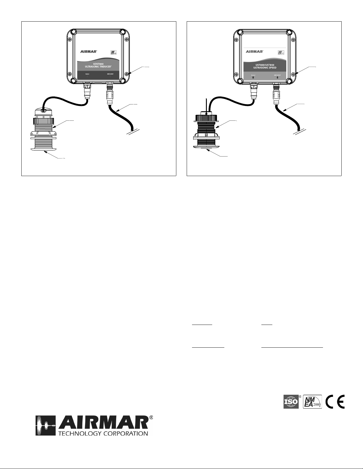
Ultrasonic Processor
for Models: UDST800, UST800, UST850
Patent http://www.airmar.com/patent.html
Applications
Connect to an NMEA 2000 network.
Installation
Locating the Ultrasonic Processor
CAUTION: If the processor will be mounted on a vertical surface,
face the connectors downward to avoid water seeping into the box.
1. Select a convenient, dry, mounting location for the water-
resistant Ultrasonic Processor a minimum of 1m (3') from other
cables and electronic equipment.
2. Hold the processor at the selected location and mark the
position of the four screw holes with a pencil.
3. At the marked locations, drill a 3mm or 1/8" hole to a depth of
10mm (3/8").
4. Fasten the processor to the selected mounting surface, using
the screws supplied.
Routing the Cables & Connecting
CAUTION: Do not remove connectors to ease cable routing. If the
cable must be cut and spliced, use Airmar’s splash-proof Junction
Box No. 33-035 and follow the instructions supplied. Removing
the waterproof connector or cutting the cable, except when using
a watertight junction box, will void the sensor’s warranty.
1. Route the cables to the Ultrasonic Processor. Be careful not to
tear the cable jacket when passing it through the bulkhead(s)
and other parts of the boat. Use grommets to prevent chafing. To
reduce electrical interference, separate the sensor cable from
other electrical wiring and the engine. Do not fasten the cables
in place at this time.
2. Connect the cables to the Ultrasonic Processor (Figure 1 or 2).
3. Fasten all the cables in place. Coil any excess cable and
secure it with cable-ties to prevent damage.
Record the information found on the cable tag for future reference.
Part No._________________Date___________
Follow the precautions below for optimal
product performance and to reduce the risk of
property damage, personal injury, and/or death.
WARNING: Always wear safety glasses, a dust mask,
and ear protection when installing.
WARNING: The power must be OFF before proceeding.
WARNING: The power supply voltage must be
9 – 16VDC.
WARNING: A safe installation requires a 0.5 amp fast-
blow fuse or circuit breaker.
CAUTION: To reduce electrical interference from
other electrical wiring and any on-board equipment with
strong magnetic fields such as radar equipment, radio
transmitters, boat engines, generators, etc., separate
the Ultrasonic Processor and cables by at least 1m (3').
CAUTION: Never use solvents. Cleaner, fuel, sealant,
paint, and other products may contain solvents that
can damage plastic parts.
IMPORTANT:Read the instructions completely
before proceeding with the installation. These
instructions supersede any other instructions in your
instrument manual if they differ.
OWNER’ S GUIDE & INSTALLATION INSTRUCTIONS
Tools & Materials
Safety glasses
Dust mask
Ear protection
Pencil
Electric drill
Drill bit 3mm or 1/8"
Phillips screwdriver
Grommet(s) (some installations)
Cable ties