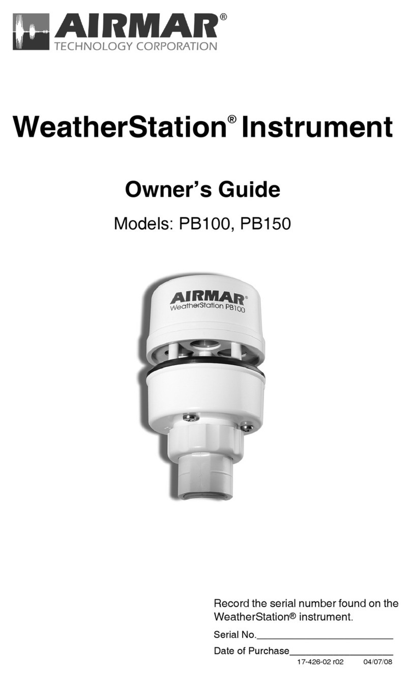
Airmar PB100 WeatherStation User manual

Record the serial number found on the
WeatherStation for future reference.
Serial No._________________________
Date of Purchase___________________
WeatherStation
Powerboat Model PB100
Owner’s Guide
17-426-01 r01 02/01/06

Copyright © 2005, 2006 Airmar Technology Corp. All rights reserved.

3
Table of Contents
Introduction 4
Adding External Sensors 5
Choosing the Mounting Location 6
Tools & Materials 7
Installing 8
Cable Routing & Connecting 11
Connecting to a Converter 11
Connecting to a Combiner 13
Connecting to a Generic NMEA Display 23
Installing the Software 25
Setting Up the WeatherCaster Program 30
Using the WeatherCaster Program 35
Maintenance & Updates 43
Where to Purchase Parts 43
Troubleshooting 44
Appendix A—How the WeatherStation Works 51
Appendix B—Technical Information 57
Acronyms & Glossary 58

4
Introduction
Thank you for purchasing the Airmar Ultrasonic WeatherStation. This exciting
product is actually six different sensors in a single unit—without any moving parts.
The compact housing is fully waterproof with a single removable cable. Data is
output in digital NMEA 0183 format.
Functions of the WeatherStation
• Apparent wind speed
• Apparent wind direction
• Magnetic compass heading
• Air temperature
• Relative humidity
•Dew point temperature
• Wind chill temperature
• Barometric pressure
• Global Positioning System (GPS)
•Vessel speed over ground (SOG)
•Vessel course over ground (COG)
•True wind speed
•True wind direction
• Heading relative to true north
•True wind chill temperature
•True wind speed relative to water—requires speed-through-water input
IMPORTANT: Please read the owner’s guide
completely before proceeding with the installation.
These instructions supersede any other instructions
in your instrument manual if they differ.

5
Adding External Sensors
The WeatherStation can receive data from external sensors when they are
connected through an optional Combiner. This device processes additional
received data and transmits it to the WeatherStation for use in true wind
calculations. The WeatherStation will automatically detect whether these sensors
are internal, external, or not available at all. Simply connect the sensor(s) to the
Combiner or other NMEA 0183 repeater hardware.
The data provided by an additional sensor(s) such as heading or water depth can
also be seen on displays connected to the Combiner.
•
GPS
—An external NMEA 0183 GPS can be connected instead of or in addition
to the internal GPS. The WeatherStation gives priority to valid external GPS
data when available.
•
Compass
—If an external electronic compass is installed and working, this
external compass data will override the WeatherStation compass.
•
Speed-through-water sensor
—An external speed sensor with NMEA 0183
output can be installed, such as an Airmar Smart™ Sensor. Airmar
recommends installing the DST800V to receive water depth, boat speed, and
water temperature data.

6
Choosing the Mounting Location
For accurate readings and a reliable GPS signal, selecting the best location for
the WeatherStation is very important. Easy access and appearance should be
secondary considerations. Since each installation is unique, the best separation
distances from other equipment on the boat will vary depending on the particular
equipment and how it is configured. Choose a location that balances the
requirements below (see Figure 1).
•The WeatherStation
must
be mounted in “clear air”—away from obstructions in
any direction that will interfere with air flowing through the unit. If there is an
obstruction,
be sure
to mount the WeatherStation at least 2m (6') away. On
land, avoid roof tops, chimneys, trees, etc.
• If possible, mount the WeatherStation higher than any other object. Mount it a
minimum of 500mm (20") above the surrounding surfaces. For land use, mount
a minimum of 10m (33') above sea level.
• Because the WeatherStation has an electronic compass, it should be at least
1 m (3') away from any on-board radar equipment or other strong magnetic
fields from equipment such as radio transmitters, boat engines, generators, etc.
• Because the WeatherStation has a GPS, it
must
be lower than any on-board
INMARSAT communications antenna.
• Because the WeatherStation has a GPS,
be sure
it is as far as possible from
high-powered transmitting antennas to avoid mutual interference.
• Because the WeatherStation has a GPS, check for any electromagnetic
shading. That is, any obstructions from other vessels or shoreline buildings that
will interfere with the GPS signals that the WeatherStation
must
receive.
Figure 1. Antennas
Courtesy of Northstar BNT, Acton, MA
Min. 1m

7
Tools & Materials
Antenna mount with standard 1” - 14 marine threads and a pass-through for the
cable (see Figure 2)
Hardware to install the antenna mount
Extension tube (optional)
Pencil
Level
Safety goggles
Dust mask
Electric drill
Drill bits
Phillips screwdrivers
Plumber’s tape (optional)
Cutting pliers (some installations)
Wire strippers (some installations)
Electrical tape (some installations)
Converter (some installations)
Combiner (some installations)
Where to Purchase
USA & Canada Gemeco Tel: 843.394.3565
Fax: 843.394.3736
email: sales@gemeco.com
Europe Airmar Europe Tel: 45.45.81.04.18
& Rest of World Fax: 45.45.81.04.93
email: [email protected]
Figure 2. Antenna mounts
ratchet mountdeck mount
cable
passes
through
center
deck mount
of mount
Copyright © 2005 Airmar Technology Corp.
cable
pass-through
with extension
extension
with cable
pass-through

8
Installing
Caution
: The blue metal plate and the blue film found in the wind channel of the
WeatherStation are essential to its operation (see Figure 3). Be careful not to
scratch the plate, puncture the film, or damage them in any way.
Caution
: Do not remove the connector(s) to ease cable routing. If the cable must
be cut and spliced, use Airmar’s splash-proof Junction Box #33-035 and follow the
instructions provided. Cutting the cable or removing the connector, except when
using Airmar’s junction box, will void the sensor warranty.
1. Place the antenna mount at the selected location and mark the holes for the
screws (see Figure 2). Also, mark the hole in the center of the mount for the cable
to pass through. If you are using a ratchet mount,
be sure
you have purchased
an extension with a cable pass-through.
Figure 3. The wind channel
Copyright © 2005 Airmar Technology Corp.
metal plate
waterproof
film
wind channel

9
Caution
: The WeatherStation must be installed vertically—not tilted to one side.
If the WeatherStation is tilted from the horizontal plane, it will introduce an error
in the compass reading.
2. Position the antenna mount at a 90º angle to the deck. If necessary, use shims
to make the mounting surface level (see Figure 4).
Warning
: Always wear safety goggles and a dust mask.
3. Drill the holes for the mounting screws and the cable exit if necessary.
4. Using purchased screws, fasten the antenna mount in place.
5. Screw an extension tube onto the antenna mount if desired.
Figure 4. Installation
nut assembly
WeatherStation
extension tube
antenna mount
cable exit
alignment tabs
face forward
toward the bow
and parallel to
the centerline
of the vessel
wind channel
where air travels
through the sensor
(some installation)
(most installations)
Copyright © 2005 Airmar Technology Corp.

10
6. With the nut assembly on the cable near the WeatherStation connector, thread
the cable through the extension tube (if used), antenna mount, and the cable
exit. Allow several inches of cable topped by the connector above the nut
assembly (see Figure 5).
Caution
: If you use a thread lock, use plumber’s tape. Do not use a liquid
thread lock as it may weaken the plastic, causing it to swell and crack.
7. Screw the nut assembly onto the top of the antenna mount/extension tube.
Hand-tighten only
.
Do not
over tighten.
8. Remove the protective cover from the connector. (Save the cap to protect the
connector, when the WeatherStation is removed.) Plug the 7-pin connector into
the WeatherStation. The alignment key on the connector fits into a notch in the
base of the WeatherStation.
Caution
: Be sure the alignment tabs on the WeatherStation point forward
toward the bow and parallel to the centerline of the boat. This is necessary to
accurately measure wind direction and vessel heading.
9.
Be sure
the alignment tabs on the WeatherStation are facing forward toward the
bow and parallel to the centerline of the boat (see Figure 4). Slide the captive
nut upward and screw it onto the base of the WeatherStation (see Figure 5).
Hand-tighten only
.
Do not
over tighten.
Be careful NOT
to rotate the
WeatherStation or loosen the nut assembly from the antenna mount/extension
tube.
Double check to be sure
the alignment tabs are still facing forward.
Figure 5. Connecting
WeatherStation
nut
captive
nut
alignment
key
assembly
Copyright © 2005 Airmar Technology Corp.
connector

11
Cable Routing & Connecting
Depending on the equipment that you will be using, route the WeatherStation
cable to a Converter, a Combiner, or directly to a NMEA 0183 display. Go to the
section that is appropriate for your equipment.
Caution
: Do not remove the waterproof connector(s) to ease cable routing. If the
cable must be cut and spliced, use Airmar’s splash-proof Junction Box No. 33-035
and follow the instructions provided. Cutting the cable or removing the connector,
except when using Airmar’s junction box, will void the sensor warranty.
Caution
: To reduce electrical interference, separate the cables from other
electrical wiring and the engine.
Caution
: Be careful not to tear the cable jackets when passing them through
bulkheads and other parts of the boat.
Caution
: Coil any excess cable(s) and secure it with a zip-tie to prevent damage.
Connecting to a Converter
The Converter allows the WeatherStation measurements to be displayed on a PC
by converting the data from NMEA 0183 to USB.
Figure 6. Converter Installation
power
supply
PC
WeatherStation
Copyright © 2005 Airmar Technology Corp.

12
Mounting Location of the Converter
1. Select a convenient, dry, mounting location for the water-resistant Converter,
about 1 – 2 m (3' – 6') from the PC (see Figure 6).
2. Hold the Converter at the selected location and mark the position of the screw
holes. If the Converter will be mounted on a vertical surface, face the cables
downward to avoid water seeping into the box.
Warning
: Always wear safety goggles and a dust mask.
3. At the marked locations, drill the holes for the screws.
Do not
fasten the
Converter in place at this time.
WeatherStation Cable
Route the WeatherStation cable to the Converter.
Do not
connect the
WeatherStation cable or fasten it in place at this time.
USB Cable
Route the USB cable coming from the Converter into the USB port on the PC.
Do not
connect the cable or fasten it in place at this time.
Power Cable
Warning
: The power panel must have a 1 amp fast-blow fuse or circuit breaker.
1. Route the power cable from the Converter to the power supply.
Do not
fasten the
power cable in place at this time.
2. Allowing an extra 25 cm (10") for wiring ease, cut the cable to length.
3. Strip 60mm (2-1/2") of the outer jacket and foil shielding from the cut end of the cable.
4. Cut off the bare wire flush with the cable jacket.
5. Strip 10 mm (3/8") of conductor insulation from the end of each colored wire.
6. Protect the cable’s foil shielding from causing a short by wrapping electrical
tape around the jacket where the wires emerge from the cable. The tape
must
overlap the wires a minimum of 6 mm (1/4").
7. Connect the wires to the power supply (10 – 16 V and 0.5 amp required).
See the color code below.
Red 12 VDC +
Black 12 VDC –
Note
: the Converter is powered by the USB port and the WeatherStation is
powered by the power cable.
Completing the Installation
1. Fasten the Converter in place with the screws supplied.
2. Plug the WeatherStation cable into the Converter.
3. Plug the USB cable into the PC.
4. Fasten all the cables in place.
LED Indicator Light
The green LED indicator light will flash when the Converter is operating.
Install the Software
Go to “Installing the Software”.

13
Connecting to a Combiner
The Combiner allows the WeatherStation data to be displayed simultaneously on
both an NMEA display and a PC. On the Combiner, the two auxiliary grommets
labeled AUX NMEA OUT can be used to connect additional devices capable of
displaying WeatherStation data (see Figure 7). All display devices
must
be NMEA
0183.
What does NMEA IN and NMEA OUT mean?
NMEA IN represents
input
for data flowing into a NMEA device. An IN device is a
NMEA listener. NMEA OUT signifies
output
for data flowing out of a device. OUT
devices are NMEA talkers. The Combiner label
designates data flow as viewed by
the device itself
. For example, the Combiner’s
output
should be connected to a
display’s
input
.
The
output
of any NMEA device (talker) may connect to the
inputs of multiple
devices
(listener). However, it is not permissible to connect the
output
of one
NMEA device to the
output
of another. If the need arises to provide data from the
outputs of two or more devices to the input of a given device, then a Combiner is
required.
Caution
: Be sure to connect a NMEA talker to the NMEA IN terminal and NMEA
listeners to the NMEA OUT terminals.
Caution
: When connecting NMEA devices to one another, the cable shield only
connects at ONE end of the cable, preferably at the device providing the NMEA
output.
power
supply
NMEA display
Airmar
or other sensor
Figure 7. Combiner installation
additional
display
additional
display
Weather
or additional
Smart™ Sensor
PC
sensor
Station
Copyright © 2005 Airmar Technology Corp.

14
Mounting Location of the Combiner
1. Select a convenient, dry, mounting location for the water-resistant Combiner,
about 1 – 2 m (3' – 6') from the NMEA device and the PC.
2. Hold the Combiner at the selected location and mark the position of the screw
holes. Note—If the Combiner will be mounted on a vertical surface, face the
grommets to the sides to avoid water seeping into the box.
Warning
: Always wear safety goggles and a dust mask.
3. At the marked locations, drill the holes.
Do not
fasten the Combiner in place at
this time.
WeatherStation Cable
Route the WeatherStation cable to the Combiner.
Do not
connect the
WeatherStation cable or fasten it in place at this time.
USB Cable
Route the USB cable coming from the Combiner to the USB port on the PC.
Do not
connect the cable or fasten it in place at this time.
NMEA Display/Additional Sensor Cable
1. Route the cable coming from the NMEA display/additional sensor to the
Combiner.
Do not
fasten the cable in place at this time.
2. Allowing an extra 25 cm (10") for wiring ease, cut the cable to length.
3. Remove the cover of the Combiner to expose the terminals inside
(see Figure 8).
Figure 8. Inside the Combiner
AIRMAR
WEATHER STATION
25-431-01
NMEA DISPLAY
ACTIVE RESEARCH LTD 2005
C
SHIELD
A/+ B/- A/+ B/ - + A/+
NMEA IN
NMEA OUT
POWER
NMEA
IN
SHIELD
NMEA IN
NMEA OUT
POWER
NMEA
IN
- +
B/-
B/- A/+ B/- A/+
USB
050818-001 ACTIS
SHIELD
PWR
GND
DM
DP
NMEA MULTIPLEXER
Copyright © 2005 Airmar Technology Corp.
power PC
cable cable

15
4. Using a small Phillips screwdriver, puncture the grommet that corresponds to
NMEA Display on the cover (see Figure 7).
Be careful
not to damage the circuit
board.
5. Push approximately 200mm (8") of the cable through the grommet (see
Figure 9). To ease sliding, apply alcohol to the cable jacket.
6. Strip 60mm (2-1/2") of the outer jacket and foil shielding from the cut end of the
cable.
7. Strip 10 mm (3/8") of conductor insulation from the end of each colored wire.
8. Protect the cable’s foil shielding from causing a short by wrapping electrical
tape around the jacket where the wires emerge from the cable. The tape
must
overlap the wires a minimum of 6 mm (1/4").
9. From outside the Combiner,
carefully
pull the cable until only 13mm (1/2") of the
cable jacket remains inside.
Figure 9. Wiring a NMEA display to the Combiner
AIRMAR
WEATHER STATION
25-431-01
NMEA DISPLAY
ACTIVE RESEARCH LTD 2005
C
SHIELD
A/+ B/- A/+ B/- - + A/+
NMEA IN
NMEA OUT
POWER
NMEA
IN
SHIELD
NMEA IN
NMEA OUT
POWER
NMEA
IN
- +
B/- B/- A/+ B/- A/+
USB
050818-001 ACTIS
SHIELD
PWR
GND
DM
DP
NMEA MULTIPLEXER
NMEA
display
cable
Copyright © 2005 Airmar Technology Corp.
power PC
cable cable

16
10.Connect each wire in turn into the designated NMEA Display terminal. Loosen
the screw, insert the stripped end of the wire into the square hole, and retighten
the screw.
Be sure the stripped end of the wire is inserted up to its insulation
only
.
Do not
include any insulation inside the terminal. Gently tug on the wire to
ensure that it is securely fastened. Repeat this process until all the wires are
connected. Refer to the owner’s manual that came with the display/sensor and
the wiring diagram below (see Figure 10).
Figure 10. Wiring diagram to connect a NMEA display
AIRMAR
WEATHER STATION
25-431-01
NMEA DISPLAY
ACTIVE RESEARCH LTD 2005
C
SHIELD
A/+ B/- A/+ B/- - + A/+
NMEA IN
NMEA OUT
POWER
NMEA
IN
SHIELD
NMEA IN
NMEA OUT
POWER
NMEA
IN
- +
B/- B/- A/+ B/- A/+
USB
050818-001 ACTIS
SHIELD
PWR
GND
DM
DP
NMEA MULTIPLEXER
SHIELD
NMEA OUT
POWER
- +
B/- A/+
NMEA IN
B/- A/+
See the NMEA display manual
for power and shield connections.
Note: Power is available from
the Combiner as shown by
the dashed lines.
Copyright © 2005 Airmar Technology Corp.

17
Auxiliary NMEA IN Grommet.
Use the AUX NMEA IN grommet to connect an external NMEA 0183 sensor such
as: an Airmar Smart™ Sensor, an external GPS, an external compass, or other
sensor. An “IN” device will supply additional data to the WeatherStation.
The WeatherStation software (WeatherCaster) will automatically detect a Smart™
Sensor and display the appropriate data. Airmar recommends installing the
DST800V to receive water depth, boat speed, and water temperature data. Other
Smart™ Sensors can be connected, provided that your NMEA display can read
the sentence output and is configured to display those values.
The AUX NMEA IN grommet can also be used to connect an external GPS. In
some cases, a GPS receiver can be plugged directly into a NMEA port on the
display, if it can repeat the input to the Combiner. This would leave the AUX NMEA
IN grommet on the Combiner free to connect an Airmar Smart™ Sensor.
To wire a device through the AUX NMEA IN grommet, use the NMEA IN terminals
on the printed circuit board (see Figure 11).
Figure 11. Wiring an external sensor to the Combiner
AIRMAR
WEATHER STATION
25-431-01
NMEA DISPLAY
ACTIVE RESEARCH LTD 2005
C
SHIELD
A/+ B/- A/+ B/- - + A/+
NMEA IN
NMEA OUT
POWER
NMEA
IN
SHIELD
NMEA IN
NMEA OUT
POWER
NMEA
IN
- +
B/- B/- A/+ B/- A/+
USB
050818-001 ACTIS
SHIELD
PWR
GND
DM
DP
NMEA MULTIPLEXER
Copyright © 2005 Airmar Technology Corp.
external
sensor
cable
NEMA
display power PC
cable cable cable

18
1. Route the cable coming from the external sensor to the Combiner.
Do not
fasten
the cable in place at this time.
2. Allowing an extra 25 cm (10") for wiring ease, cut the cable to length.
3. Remove the cover of the Combiner to expose the terminals inside (see
Figure 11). Using a small Phillips screwdriver, puncture the grommet that
corresponds to AUX NMEA IN on the cover (see Figure 7).
Be careful
not to
damage the circuit board.
4. Push approximately 200mm (8") of the cable through the grommet (see Figure 11).
5. Strip 60mm (2-1/2") of the outer jacket and foil shielding from the cut end of the cable.
6. Strip 10 mm (3/8") of conductor insulation from the end of each colored wire.
7. Protect the cable’s foil shielding from causing a short by wrapping electrical
tape around the jacket where the wires emerge from the cable. The tape
must
overlap the wires a minimum of 6 mm (1/4").
8. From outside the Combiner,
carefully
pull the cable until only 13mm (1/2") of the
cable jacket remains inside.

19
9. Connect each wire in turn into the designated NMEA IN terminal. Loosen the
screw, insert the stripped end of the wire into the square hole and retighten the
screw.
Be sure the stripped end of the wire is inserted up to its insulation only
.
Do not
include any insulation inside the terminal. Gently tug on the wire to
ensure that it is securely fastened. Repeat this process until all the wires are
connected. Refer to the owner’s manual that came with the sensor and the
wiring diagram below (see Figure 12).
AIRMAR
WEATHER STATION
25-431-01
NMEA DISPLAY
ACTIVE RESEARCH LTD 2005
C
SHIELD
A/+ B/- A/+ B/- - + A/+
NMEA IN
NMEA OUT
POWER
NMEA
IN
SHIELD
NMEA IN
NMEA OUT
POWER
NMEA
IN
- +
B/- B/- A/+ B/- A/+
USB
050818-001 ACTIS
SHIELD
PWR
GND
DM
DP
NMEA MULTIPLEXER
SHIELD
NMEA OUT
POWER
- +
B/- A/+
Figure 12. Wiring diagram to connect an external sensor
Copyright © 2005 Airmar Technology Corp.
See the NMEA display manual
for power and shield connections.
Note: Power is available from
the Combiner as shown by
the dashed lines.

20
Auxiliary NMEA OUT Grommets
Use the AUX NMEA OUT grommets to connect one or two additional devices to
receive and display data from the WeatherStation. To wire a device(s) through the
AUX NMEA OUT grommet(s), use the NMEA OUT terminals on the printed circuit
board (see Figure 13).
Note: If you will be connecting two devices, wire both devices to the same
designated terminals—on top of one another.
1. Route the cable coming from the additional display device(s) to the Combiner.
Do not
fasten the cable in place at this time.
2. Allowing an extra 25 cm (10") for wiring ease, cut the cable to length.
3. Remove the cover of the Combiner to expose the terminals inside.
4. Using a small Phillips screwdriver, puncture the grommet(s) that corresponds to
AUX NMEA OUT on the cover (see Figure 7).
Be careful
not to damage the
circuit board.
Figure 13. Wiring additional display devices to the Combiner
AIRMAR
WEATHER STATION
25-431-01
NMEA DISPLAY
ACTIVE RESEARCH LTD 2005
C
SHIELD
A/+ B/- A/+ B/- - + A/+
NMEA IN
NMEA OUT
POWER
NMEA
IN
SHIELD
NMEA IN
NMEA OUT
POWER
NMEA
IN
- +
B/- B/- A/+ B/- A/+
USB
050818-001 ACTIS
SHIELD
PWR
GND
DM
DP
NMEA MULTIPLEXER
additional
display additional
display
grommet
cable
Copyright © 2005 Airmar Technology Corp.
NMEA
display
cable
power
cable PC
cable
Other manuals for PB100 WeatherStation
3
Table of contents
Other Airmar Weather Station manuals

Airmar
Airmar PB100 WeatherStation User manual

Airmar
Airmar 300WXR Instruction Manual

Airmar
Airmar PB100 WeatherStation User manual

Airmar
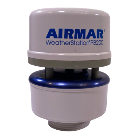
Airmar PB200 User manual

Airmar
Airmar PB100 WeatherStation User manual

Airmar
Airmar WeatherStation 110WX User manual

Airmar
Airmar PB200 Instruction Manual

Airmar
Airmar WeatherStation 200WXR Instruction Manual
Airmar
Airmar 300WXR, 300WX, 150WX, 100WX w/CAN,100WX User manual