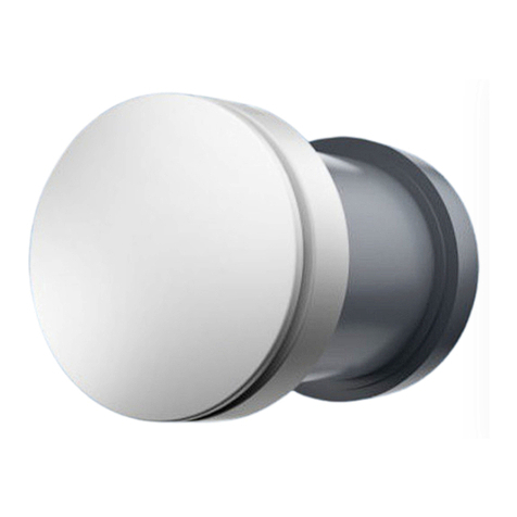
airmaster AM 150 User manual

1.2 .3
AM 150 .300 .500 .800 .900 .1000 .1200; AMC 150; DV 1000
INSTALLATION
CONNECTIONS .COMMUNICATION .COMMISSIONING

This Manual must be read before installing
the Airmaster air handling unit. Following
this Manual will ensure this product is oper-
ated correctly.
The installation contractor is responsible for
ensuring that the unit is installed according
to current regulations and standards.
When installing the air handling unit in a room
with a re or stove drawing air from the room,
all applicable provisions must be observed.
The unit should not be used in rooms with
abrasive particles or ammable or corrosive
gas in the air, in wet rooms (not CV-series) or
explosion-protected rooms.
The unit should not be used without the
lters specied in the Operator’s Manual.
The manufacturer cannot be held liable for
damage arising from use or installing in
contravention of these instructions.
The manufacturer reserves the right to make
changes without notice. All values stated
are nominal values and can be aected by
local conditions.
Failure to observe the warnings indicated by
a danger symbol implies a risk of personal
injury or damage to property.
This manual relates to the Airmaster unit it
accompanies plus all equipment, and must
be given to and saved by the unit’s owner.
All necessary data and guides to network
integration can be downloaded from www.
airmaster-as.com.
SAFETY INSTRUCTIONS
WARNINGS
Place of installation and serial numbers (S/N):
Type:
Delivery date:
Place of installation:
S/N of Air handling unit:
S/N of Cooling Module:
Service covers may not be opened without
rst disconnecting the unit’s power supply
and preventing use.
The unit may not be started up until all service
covers and grates on duct connections have
been installed.

Table of Contents
1. Technical Specications ................................................................................................................................5
2. Condensate Drain ...........................................................................................................................................7
3. Heating Surfaces ........................................................................................................................................... 8
3.1. Water Heating Surface ..................................................................................................................................................................................8
3.1.1. Bleeding...............................................................................................................................................................................................8
3.1.2. Setting the Line Regulating Valve............................................................................................................................................9
3.1.3. Frost Protection Valve ...................................................................................................................................................................9
3.1.4. Setting the Contol Valve...............................................................................................................................................................9
3.1.5. Check Heating Surface................................................................................................................................................................10
3.2. Electric Heating Surfaces ...........................................................................................................................................................................10
4. Electrical Installation ...................................................................................................................................11
4.1. Supply Voltage ................................................................................................................................................................................................ 11
4.2. Connection of Electrical Equipment....................................................................................................................................................... 11
4.2.1. Data Cable.........................................................................................................................................................................................12
4.2.2. Shield Termination........................................................................................................................................................................12
4.2.3. Control Panel....................................................................................................................................................................................12
4.2.4. Motion (PIR) Sensor......................................................................................................................................................................12
4.2.5. Carbon Dioxide (CO2) Sensor .....................................................................................................................................................13
4.2.6. External Stop Function................................................................................................................................................................13
4.2.7. External Start ..................................................................................................................................................................................13
4.2.8. Boost...................................................................................................................................................................................................13
4.2.9. Analogue BMS.................................................................................................................................................................................14
4.3. Checking Electrical Installation ................................................................................................................................................................14
5. Airlinq BMS Installation ...............................................................................................................................15
5.1. Connectors........................................................................................................................................................................................................15
5.2. DIP Switch / Jumper.......................................................................................................................................................................................15
5.3. Wiring-diagram for typical Airlinq BMS sytemes ..............................................................................................................................15
5.4. Junction Box for Group Control Panels...................................................................................................................................................15
5.5. System Programming...................................................................................................................................................................................16
5.5.1. Programming Units ID1 to ID19................................................................................................................................................17
5.5.2. Programming ID0. .........................................................................................................................................................................18
5.5.3. Programming Group Control Panels for Groups 1 to 19..................................................................................................19
5.5.4. Programming Cooling Modules ID1 to ID19........................................................................................................................ 20
6. Commissioning and Final Inspection ..........................................................................................................21
3

Appendix 1 Wiring Diagrams............................................................................................................................23
Control Box ..................................................................................................................................................................................................................... 23
AQC-L (Black Control Box) for AMC 150, AM 150, AM(L) 300, 500 and 800 ........................................................................ 23
AQC-P (Grey Control Box) for AM(P) 500, 800, 900 and 1200, AM(S) 1000 and DV 1000............................................ 23
AQC-C (Black Control Box) for Cooling Modules and AMC 150.................................................................................................... 23
DIP Switch and Jumper................................................................................................................................................................................ 23
Standard Connections AMC 150 with AQC-L (Black Control Box)............................................................................................................ 24
Standard Connections AM 150, 300, 500 and 800 with AQC-L (Black Control Box)....................................................................... 25
Standard Connections AM 500, 800 and 900 with AQC-P (Grey Control Box).................................................................................. 26
Standard Connections AM 1000 and 1200 with AQC-P (Grey Control Box).........................................................................................27
Connecting the AM 1000 Sections........................................................................................................................................................ 28
Connecting the AM 1200 Sections........................................................................................................................................................ 28
Standard Connections DV 1000 with AQC-P (Grey Control Box) ............................................................................................................. 29
Wiring Diagram for Typical Airlinq BMS Systems............................................................................................................................................ 30
Individual Units, One System Control Panel....................................................................................................................................... 30
Individual Units with Cooling Module, One System Control Panel............................................................................................ 30
Individual Units with Cooling Module and Group Control Panels, One System Control Panel ........................................31
Combined System ......................................................................................................................................................................................... 32
BMS Connections......................................................................................................................................................................................................... 33
LON®.............................................................................................................................................................................................................. 33
KNX®.............................................................................................................................................................................................................. 33
BACnetTM/IP ..................................................................................................................................................................................................... 34
BACnetTM MS/TP ............................................................................................................................................................................................ 35
MODBUS®RTU RS485................................................................................................................................................................................. 36
Airmaster Airlinq®Online (Ethernet) ....................................................................................................................................................................37
Appendix 2 Error Descriptions ........................................................................................................................ 38
4

5
m3/h 147 147 300 550 725
m3/h - - 270 490 688
m3/h 115 115 240 430 650
m 3,4 3,4 6,5 7,5 8,1
l/h 10 10 10 10 10
m 6 6 6 6 6
mm/mm
4/6 4/6 8/12 8/12 8/12
mm/mm
- - 8/12 8/12 8/12
°C 75 75 75 75 75
°C 90 90 120 120 120
W - - 505 858 1379
°C - - 90 90 90
bar - - 10 10 10
- - 3/8”/DN10 1/2”/DN15
- -
s - - 60 60 60
V 1x230V+N+PE
Hz 50 50 50 50 50
W 38 48 100 132 156
A 0,3 0,4 0,6 1,1 1,1
0,55 0,52 0,56 0,58 0,56
W - 162 617 1038 1110
A - 1 3,8 6,4 6,8
- 0,7 0,7 0,71 0,71
W - 640 2450 3280 5240
W - 146 421 820 990
W 600 600 750/ 1500 - -
A 2,6 2,6 3,3/6,5 - -
W - - - 630 1000
A - - - 2,6 4,4
W - - - 1000 1500
A - - - 4,4 6,5
mA ≤0,5 ≤0,5 ≤3 ≤6 ≤6
mA - ≤1,5 ≤3 ≤2 ≤2
A 10 10 10 10 13
A 13 13 13 16 16
IP 10 10 10 10 10
1. Technical Specications
AM AMC AM AM AM
150 150 300 500 800
Max. ow rate with ePM10 75%/ePM10 75% lters at 35 dB(A)
Max. ow rate with ePM10 75%/ePM10 75% lters at 33 dB(A)
Max. ow rate with ePM10 75%/ePM10 75% lters at 30 dB(A)
Throw, max.
Condensate pump
Flow rate, max.
Pump head at ow rate 5 l/h
Drain hose air handling unit, int./ext. diameter
Drain hose cooling module, int./ext. diameter
Electric heating surface
Thermal cut-out, automatic reset
Thermal cut-out, manual reset
Water comfort heater
Power at 60/40°C Delivery/Return
Max. operating temperature
Max. operating pressure
Connections
Material Copper / aluminium
Motorised valve, opening and closing time
Electrical connection
Voltage
Frequency
Power consumption
Nominal current
Power factor
Cooling module power consumption, max.
Nominal current
Power factor
Cooling duty, nominal
Cooling duty, min.
Electric heating surface power consumption (VPH)
Nominal current
Electric comfort heater power consumption
Nominal current
Electric preheater power consumption
Nominal current
Max. leakage current on air handling unit
Max. leakage current on cooling module
Recommended fuse
Max. fuse
IP-Code
VPH: Virtual Preheat

6
m3/h 830 1100 1310 -
m3/h 760 1075 1180 -
m3/h 690 950 1050 -
m3/h - - - 1000
m 12 10,5 11 -
l/h 10 10 10 10
m 6 6 6 6
mm/mm
4/6 4/6 8/12 5/8
mm/mm
- - - 8/12
°C 75 75 75 75
°C 120 120 120 120
-
- - -
W 2345 2540 2454 4099
°C 90 90 90 90
bar 10 10 10 10
1/2”/DN15
s 60 60 60 60
V 1x230V+N+PE 3x400V+N+PE
Hz 50 50 50 50
W 240 305 254 333
A 1,8 2,2 1,4 2,6
0,6 0,6 0,6 0,6
W - - - 1449
A - - - 8,9
- - - 0,71
W - - - 6450
W - - - 1120
W - - - 2500
A - - - 10,9
W 1050 1500 1670 -
A 4,4 6,5 7,3 -
W 1500 2300 2500 -
A 6,5 10 10,9 -
mA ≤6 ≤4 ≤9 ≤7
mA - - - ≤2
A 13 3 x 13 3 x 13 3 x 13
A16 3 x 16 3 x 16 3 x 16
IP 10 10 10 40
AM AM AM DV
900M (Mix.) 1000 1200 1000
Max. ow rate with ePM
10
75%/ePM
10
75% lters at 35 dB(A)
Max. ow rate with ePM
10
75%/ePM
10
75% lters at 33 dB(A)
Max. ow rate with ePM10 75%/ePM10 75% lters at 30 dB(A)
Nominal ow rate with ePM10 75%/ePM10 75% lters
Throw, max.
Condensate pump
Flow rate, max.
Pump head at ow rate 5 l/h
Drain hose air handling unit, int./ext. diameter
Drain hose cooling module, int./ext. diameter
Electric heating surface
Thermal cut-out, automatic reset
Thermal cut-out, manual reset
Water heating surface
Water comfort heater
Water heating surface, VPH (Virtual Preheat)
Power at 60/40°C Delivery/Return
Max. operating temperature
Max. operating pressure
Connections
Material Copper / aluminium
Motorised valve, opening and closing time
Electrical connection
Voltage
Frequency
Power consumption
Nominal current
Power factor
Cooling module power consumption, max.
Nominal current
Power factor
Cooling duty, nominal
Cooling duty, min.
Electric heating surface power consumption (VPH)
Nominal current
Electric comfort heater power consumption
Nominal current
Electric preheater power consumption
Nominal current
Max. leakage current on air handling unit
Max. leakage current on cooling module
Recommended fuse
Max. fuse
IP-Code
VPH: Virtual Preheat

7
Airmaster’s AM series is delivered either with a black control
box (AQC-L) or with a grey control box (AQC-P). The DV
series is always delivered with a grey control box (ACQ-P)
AM units with AQC-L:
AM 150, AMC 150
AM 300 (specic designation: AML 300)
AM 500 (specic designation: AML 500)
AM 800 (specic designation: AML 800)
AM units with AQC-P:
AM 500 (specic designation: AMP 500)
AM 800 (specic designation: AMP 800)
AM 900 (specic designation: AMP 900)
AM 1000 (specic designation: AMS 1000)
AM 1200 (specic designation: AMP 1200)
2. Condensate Drain
We recommend connecting the air handling unit’s (AHU)/
cooling module’s (CC) condensate drain to a wastewater
pipe from a condensate pump (1.) or directly from the
condensate tray (2.)
1. All air handling units and cooling modules with a
condensate pump:
AHU/CC
NB! Fit a water lock to avoid unpleasant odours from
the wastewater system.
AHU/CC
NB! The drain hose must not be subjected to negative
pressure or a downward incline of over 0.5 m.
The dimensions for the drain hose position can be found
under “Dimensional Drawings” and “Additional Dimensions”
in the installation manuals.
2. Air handling units without condensatpump (only
possible for AM 300, 500, 800 and 1200):
(16/20 mm hose)
AHU
NB! Fit a water lock to avoid unpleasant odours from
the wastewater system.
The dimensions for the drain hose position can be found
under “Dimensional Drawings” and “Additional Dimensions”
in the installation manuals.
Optional installation of condensate drain:
The hose can also be run through the outer wall. For this
version, drill a hole of suitable diameter and with a 1-2%
outward downward gradient.
NB! Remember to seal the gap between the hose and
outer wall.
NB! THE HOSE MUST BE PROTECTED AGAINST
FORMATION OF ICE.

8
3. Heating Surfaces
3.1. Water Heating Surface
The Airmaster air handling unit DV 1000 can be tted with
an external water heating surface. AM 300, 500, 800,
900, 1000 and 1200 can be tted with an internal water
heating surface.
The water heating surface for the DV 1000 is also used to
protect against the formation of ice in the heat exchanger.
The “Virtual Preheat” function is used for this purpose.
Further details are available in the Operator’s Manual.
For this option, a motorised valve and an automatic heat
retention thermostat are tted on the heating surface. The
water heating surface is leakage tested and nal inspection
performed according to standards and rules in eect.
The heating unit’s delivery ow is connected to the con-
nection tting marked FREM (“DELIVERY”) and the return
ow to the connection tting marked RETUR (“RETURN”).
NB! The dimensioning of pipes and valves and
connection of water to the unit must always be carried
out by an authorised specialist in accordance with
current legislation and regulations.
NB! There must be clean water in the installation for
the internal valves in the water comfort heater to be
able to function optimally without problems.
It is recommended that shut-o valves, a dirt lter and
a line regulating valve be tted in accordance with the
“External connection” block diagram. It is also recommended
to mount the bleed valve and drain cock for commissioning
and service.
It may be necessary (e.g. in the case of a district heating unit)
to install a pressure dierential regulator if the pressure
dierence ∆ps exceeds 40 kPa (10 kPa = 0,1 bar). If the
dierential pressure ∆p rises above the internal construction
above 40 kPa, the risk of noise from the control valve to the
heating surface increases.
External connection:
Δp
Δps
D
BC
G
A
E
TD
F
A Internal assembly (supplied by Airmaster).
B Shut-o valve (supplied by installation contractor).
C Dirt lter (supplied by installation contractor).
D Line regulating valve (supplied by installation contractor).
E Pressure dierential regulator (supplied by installation
contractor).
F Bleed valve (supplied by installation contractor).
G Drain cock (supplied by installation contractor).
Internal construction:
In the case of DV 1000, the internal assembly is installed on
the inside of the external heating surface. In the case of AM
products, the unit must be opened for any connection work.
M
TC
1
2
3
45
6
6
1 Return connection. (Delivery connection for the AM 800.)
2 Delivery connection. (Return connection for the AM 800.)
3 Frost protection valve (Comap D3803S) with remote
temperature sensor (Comap Senso RI).
4 Control valve (Comap D3803S) with electric On/O valve
(Ballerox 43600012).
5 Water heating surface.
6 Airow.
3.1.1. Bleeding
Open the water throughow and bleed the system using
the bleed valve (F). After a short time any air noise in the
water throughow should cease.
NB! The unit must be bled with fully open valves (3 + 4).

9
3.1.2. Setting the Line Regulating Valve
If a line regulating valve is installed, it must always be set
in the interval between minimum ow and maximum ow.
• It is recommended to set the line regulation valve
to a maximum ow according to the dierential
pressure of the heating system.
• The maximum ow is calculated using the largest
known dierential pressure in the system.
• The minimum ow is calculated using the smallest
known dierential pressure in the supply system.
•
It is a prerequisite that the heat-bearing medium
in the system is raw water, with an anti-corrosive
agent added.
The following data applies to Airmaster’s heating surfaces:
Min. uid ow at
0,3 m/s (l/h)
Max. uid ow at
1,2 m/s (l/h)
AM 300 75 300
AM 500 75 300
AM 800 75 300
AM 900 120 480
AM 1000 135 540
AM 1200 120 480
DV 1000 340 1360
3.1.3. Frost Protection Valve
The sensor element (3 - TC) on the frost protection valve is
set to 8 °C (position in the middle between * and 1) to ensure
that the temperature according to the heating surface is
kept above 8 °C, and that the water in the heating surface
is free of frost. A prerequisite for this is that there is always
hot water available with a sucient dierential pressure.
NB! The heat supply or water ow must NEVER be
cut o or switched o in freezing temperatures, nor
when the air handling unit should be out of operation.
NB! The ow temperature must NEVER fall below 40°C
during periods of frost.
3.1.4. Setting the Contol Valve
The heating surface’s two valves are pre-set to 10 (com-
pletely open valve) when delivered. The freeze-protection
valve (3) must keep this setting unchanged.
The control valve (4) must be set to a value based on a critical
operation state. That is, the valve should not be limited to
the nominal ow, but must at least have “Minimum ow”
values available. When there is a high demand for heat,
the heating surface can therefore supply more than the
nominal values. On the other hand, cooling of the district
heating water is reduced.
The following data applies to Airmaster’s heating surfaces:
Nominal ow
(m3/h)
Min. uid ow
at 0,3 m/s (l/h)
Max. uid ow
at 1,2 m/s (l/h)
AM 300 300 75 300
AM 500 550 75 300
AM 800 725 75 300
AM 900 830 120 480
AM 1000 1100 135 540
AM 1200 1310 120 480
DV 1000 1000 340 1360
The valve can be set according to the calculations below
and the graph so that the required ow can be achieved
with the dierential ow of ∆ps that is available.
NB! The system must be bled before it is adjusted.
Parameters used in the calculation example:
OT Lowest outside temperature (°C)
RT Ambient temperature (°C)
Minimum eciency of heat exchanger (%)
IT Desired inlet temperature (°C)
VLInlet airow (m3/h)
tFWater temperature DELIVERY (°C)
tRWater temperature RETURN (°C)
∆p Desired dierential pressure: 20-40 kPa,
preferably around 30 kPa (10 kPa = 0.1 bar)
1.
Calculate temperature (t) according to heat
exchanger. [°C]
2. Calculate heating requirement (Q) for heating the
air to the desired inlet temperature. [W]

10
3. Calculate the desired water quantity (VV). [l/h]
4.
Use the diagram to nd the setting point for the
control valve (4).
[l/h]
10
(A)
20
30
40
50
100
500
1000
[kPa] [kV]
1
10
(B)
100
2
3
4
5
6
7
8
9
20
30
40
50
60
70
80
90
1
(C)
2 3 4 5 6
7
8
9
10
•
Plot the calculated water quantity (A) on the dia-
gram. (Here VV = 150 l/h)
•
Plot the desired dierential pressure for the control
valve (B) on the diagram. Here, ∆p = 30 kPa. (The
optimal value for the valve is between 20 and 40
kPa.)
• Use the diagonal lines to read o the value (C) for
the valve setting.
•
Set the valve to the calculated value using the
presetting key. (In this example the control valve
is set to 4,5.)
Nominal ow and heat output apply to a winter state in
which:
•
The outdoor air is = -12 °C, 90% relative air humidity.
• The indoor air is = 22 °C, 20% relative air humidity.
• The heating supply’s ow temperature is = 60 °C.
Nominal ow
(m3/h)
Nominal
power (W)
Nominal uid
ow (l/h)
AM 300 300 505 19
AM 500 550 858 53
AM 800 725 1379 60
AM 900 830 2345 111
AM 1000
1100 2540 112
AM 1200
1310 2454 107
DV 1000 1000 4099 180
3.1.5. Check Heating Surface
yes no
Water pipes connected correctly to heating plant
Heating surface is bled
Heating surface is waterproof
Frost protection valve adjusted to
Control valve adjusted to
Line regulating valve
installed and adjusted to
Pressure dierential regulator
installed and adjusted to
Name of installation engineer:
Comment:
3.2. Electric Heating Surfaces
Airmaster units can be supplied with one or two built-in
electric heating surfaces. In such cases, the safety ther-
mostats are installed inside the unit.
Electric heating surfaces for AMC 150, AM 150, AM 300
and DV 1000 are installed as comfort heaters but are also
used to protect against the formation of ice in the heat
exchanger. The “Virtual Preheat” function is used for this
purpose. See the Operator’s Manual.
NB! Electric heating surfaces consume more power.
For further details, see “Technical Specications”.
Safety functions on an electric heating surfaces:
The electric heating surfaces are protected against
overheating by two safety thermostats for each heating
surface, which disconnect the heating surfaces in the event
of overheating.
The safety thermostats are installed in the heating surface.
•
One of the thermostats disconnects the heating
surface and is equipped with an automatic reset.
For further details, see “Technical Specications”.
•
The second thermostat also disconnects the heating
surface but is equipped with a manual reset. For
further details, see “Technical Specications”.

11
4. Electrical Installation
NB! All electrical connections to the unit must be
carried out by an authorised specialist in accordance
with current legislation and regulations.
NB! The length of all leads used in the installation
must be adjusted to t.
NB! The power supply MUST be switched o for all
connection work.
4.1. Supply Voltage
NB! A pre-fuse and safety switch disconnector must
be tted as part of the permanent installation for
the unit in accordance with current legislation and
regulations. Pre-fuse and safety switch disconnector
are supplied by the installation contractor.
NB! The supply cable must be dimensioned in
accordance with current rules and regulations, taking
into account the conditions at the installation location.
NB! Depending on the unit’s power consumption and
the existing electrical system, it may be necessary to
set up at least one new power circuit.
NB! When a number of units are installed, the
permitted leakage current per unit must be taken
into consideration. For further details, see “Technical
Specications”.
NB! The control panel, as well as any sensors, switches
and optional items, must be tted before the supply
voltage is connected.
NB! Electrical equipment must be connected in
accordance with “Appendix 1 Wiring Diagrams”.
Only AM 1000, AM 1200 and DV 1000:
The units must be connected to the power supply using
a 5-wire power supply cable (5x2,5 mm2, supplied by the
installation contractor) for 3-phase operation (L1, L2, L3,
N, PE).
4.2. Connection of Electrical Equipment
Electrical equipment is connected at the control box:
•
In the case of AMC 150, AM 150, 300, 500, 800 and
1000, under the base plate.
• In the case of AM 900, behind the front cover.
•
In the case of AM 1200, under a service panel on
the top of the unit’s motor section.
• In the case of DV 1000, under the service panel on
the side of the unit.
NB! All connection work MUST be carried out with
the power supply switched o in accordance with
“Appendix 3, Wiring Diagrams” .
AMC 150, AM 150, 300, 500 and 800 with AQC-L (black
control box)
The AQC-L has 3 analogue inputs available. Input AI#1
(J17-5) is programmed as standard for a movement sensor
(“PIR”), AI#2 (J17-7) for overriding the ow by means of a
CO2sensor (“CO2 Sensor 1”) and AI#3 (J17-11) for external
start (“Ext start”).
AM 500, 800, 900, 1000 and 1200 and DV 1000 with
AQC-P (grey control box)
The AQC-P has 3 digital and 3 analogue inputs. Input DI#1
(J1-7) is programmed as standard for a movement sensor
(“PIR”), DI#2 (J1-6) for external start (“Ext start”), DI#3
(J1-5) for start via an A-BMS (“A-BMS Start”), AI#1 (J1-14)
for ow control via A-BMS (”A-BMS Flow”), AI#2 (J1-13)
for inlet temperature control via A-BMS (”A-BMS Temp”)
and AI#3 (J1-12) for overriding the ow by means of a CO2
sensor (“CO2 Sensor 1”).
Inputs on all units can be programmed for other signal
sources.
NB! Other settings in the control system software must
be performed using a PC running the Airlinq Service
Tool. The program can be downloaded from
www.airlinq.eu.

12
4.2.1. Data Cable
The connection cable for the control panel is a shielded
twisted pair (STP) 2x2x0.6 data cable. Sensors can also be
connected with a non-twisted pair but shielded data cable.
The following instructions apply when preparing the cable
for the terminals in the panel/sensor:
•
Strip the insulation from the sheathing and shielding
as closely to the connection terminations as possible
for reasons of EMC noise.
• When stripping the insulation, take care to ensure
that the leads are not damaged and do not break.
• Maintain the twisted pairing of the leads right up
to the terminals.
The following instructions apply when connecting the cable
to the unit’s optional plug:
•
Strip the insulation as closely to the connection
terminals as possible for reasons of EMC noise.
• When stripping the insulation, take care to ensure
that the leads are not damaged and do not break.
• Maintain the twisted pairing of the leads right up
to the terminals.
• Terminate the shield (see “Shield Termination”).
Electrical equipment must be connected according to the
wiring diagrams shown in “Appendix 1 Wiring Diagrams”.
NB! The length of all leads used in the installation
must be adjusted to t.
4.2.2. Shield Termination
The following instructions apply to termination of the shield
for both the control panel and all sensors next to the control
box inside the air handling unit.
Connect drain wire to ground (GND), cut away shielding foil.
NB! The shield must be removed at the control panel
and sensors. Do not over-tighten the screws.
4.2.3. Control Panel
The delivery usually includes a control panel (loose) and a
pre-tted, 6,5-metre cable.
Mount the control panel at a suitable height on the wall,
usually in the same room as the air handling unit. It may,
however, be placed in an adjacent room.
NB! Leads for A/B and 12 V/GND must be twisted pair.
The screen must be carefully removed to prevent
short-circuiting.
Electrical equipment must be connected according to the
wiring diagrams shown in “Appendix 1 Wiring Diagrams”.
4.2.4. Motion (PIR) Sensor
The connection cable for the PIR sensor is a shielded data
cable.
On delivery, the sensor is unconnected and without a lead.
If possible, the sensor should be installed 2,25 m (1,8-2,5
m) above the ground. Further details are available under
“Positioning the unit” in the installation manual.
Electrical equipment must be connected according to the
wiring diagrams shown in “Appendix 1 Wiring Diagrams”.

13
4.2.5. Carbon Dioxide (CO2) Sensor
The Airmaster air handling unit is also available with a CO2
sensor. This sensor is available as an internally wired and
tted sensor or as an external sensor (shown here).
The CO2sensors have a sensor range of 0-2000 ppm CO2.
On delivery, the sensor is unconnected and without a lead.
If possible, the sensor should be installed 2 m above the
ground at a distance of 1 m from the unit’s extract air duct.
Further details are available under “Positioning the unit” in
the installation manual.
All AM and DV units must be connected according to the
wiring diagrams shown in “Appendix 1 Wiring Diagrams”.
4.2.6. External Stop Function
The “External Emergency Stop” function can shut down
the unitindependently of other start signals, e.g. in an
emergency.
The unit is supplied with its own low voltage signal, e.g. by
means of a smoke detector via a normally open (NO) contact
for as long as the unit is in operation. The unit is started
by the programmed start signals. If the function signal is
disrupted (contact opens), the unit will stop immediately,
regardless of status.
AMC 150, AM 150, 300, 500 and 800 with AQC-L (black
control box)
1
J17-4
J17-5 / 7 / 11
Connect a 13.5 VDC signal, e.g. using a smoke detector via
a contact (1) from terminal J17-1 to terminal J17-5 (AI#1),
J17-7 (AI#2) or J17-11 (AI#3).
Input AI#1, AI#2 or AI#3 must be set to “External Emergency
Stop” using a PC running the Airlinq Service Tool.
AM 500, 800, 900, 1000 and 1200, DV 1000 with
AQC-P (grey control box)
1
J1-8
J1-5 / 6 / 7
Connect a 12 VDC signal, e.g. using a smoke detector via a
contact (1) from terminal J1-8 to terminal J1-5 (DI#3), J1-6
(DI#2) or J1-7 (DI#1).
Input DI#3, DI#2 or DI#1 must be set to “External Emergency
Stop” using a PC running the Airlinq Service Tool.
4.2.7. External Start
The unit is supplied with its own low voltage signal, e.g. via
an external contact (e.g. a circuit breaker or a hygrostat).
The unit starts when the contact closes. If the signal is
disrupted, the unit will stop.
Electrical equipment must be connected according to the
wiring diagrams shown in “Appendix 1 Wiring Diagrams”.
4.2.8. Boost
The boost function can be used to adjust the airow
temporarily. The function is programmed with xed control
voltages for both the supply and the exhaust fan and, if
applicable, with afterow time. It is possible to adjust the
control voltages for the fans independently of each other
if unbalanced ventilation is required.
The unit is supplied with its own low voltage signal, e.g. via
an external contact (e.g. a switch) (1). The air handling unit
stops normal operation and activates the boost function
when the contact closes. If the signal is disrupted, the unit
will return to the previous operating mode. If the air handling
unit has stopped, the boost function will start the unit.
AMC 150, AM 150, 300, 500 and 800 with AQC-L (black
control box)
1
J17-4
J17-5 / 7 / 11
Connect a 13.5 VDC signal via an external contact (e.g. a
switch) (1) from terminal J17-1 to terminal J17-5 (AI#1),
J17-7 (AI#2) or J17-11 (AI#3).
Input AI#1, AI#2 or AI#3 must be set to “Boost” using a
PC running the Airlinq Service Tool. The control voltages
and, if applicable, after run time for the function must be
programmed.

14
AM 500, 800, 900, 1000 and 1200, DV 1000 with
AQC-P (grey control box)
1
J1-8
J1-5 / 6 / 7
Connect a 12 VDC output signal from terminal J1-8 via an
external contact (e.g. a switch) (1) to terminal J1-5 (DI#3),
J1-6 (DI#2) or J1-7 (DI#1).
Input DI#1, DI#2 or DI#3 must be set to “Boost” using a
PC running the Airlinq Service Tool. The control voltages
and, if applicable, after run time for the function must be
programmed.
4.2.9. Analogue BMS
An Airmaster air handling unit can be connected to an
Analogue Building Management System (A-BMS).
AMC 150, AM 150, 300, 500 and 800 with AQC-L (black
control box)
3
4
5
J17-7
J17-11
J17-8
J17-8
J17-4
J17-5
0-10V
0-10V
GND
GND
The BMS system passes the 13.5 VDC output signal via
contact (NO) (3) from terminal J17-4 on terminal J17-5
(AI#1). Consequently, the ventilation unit will start and
stop according to the BMS system’s programming.
The airow volume (4) and inlet temperature (5) are
controlled by a potential-free 0-10 volt signal on terminal
J17-7 (AI#2), on terminal J17-11 (AI#3) and GND on terminal
j17-8 of the A-BMS (4, 5).
Input AI#1 must be set to “A-BMS Start”, input AI#2 to
“A-BMS Flow” and input AI#3 to “A-BMS Temp” using a PC
running the Airlinq Service Tool.
If you simply wish to stop or start the unit using A-BMS,
and otherwise let it assume the airow volume and inlet
temperature set on the control panel or set by, e.g. a CO2
sensor, the start signal only should be connected to “Ext
start”.
Electrical equipment must be connected according to the
wiring diagrams shown in “Appendix 1 Wiring Diagrams”.
AM 500, 800, 900, 1000 and 1200, DV 1000 with
AQC-P (grey control box)
For all Airmaster air handling units with AQC-P, the A-BMS
connection is programmed ex works. Electrical equipment
must be connected according to the wiring diagrams shown
in “Appendix 1 Wiring Diagrams”.
4.3. Checking Electrical Installation
yes no
Control panel installed
PIR sensor installed
CO2sensor installed
External stop installed
External start installed
Boost installed
A-BMS installed
Power supply installed
Inputs programmed
Name of installation engineer:
Comment:

15
12V 12V
GND GND
A A
B B
12V 12V
GND GND
A A
B B
Panel (ID179)
System Control
GND
A
B
12V
GND
GND
A
A
B
B
12V
12V
A
A
B
B
GND
A
B
12V
Unit (0) (ID0)
PTS 2x2x0,6
PTS 2x0,6
12V 12V
GND GND
A A
B B
A A
B B
DIP Switch
Unit (1)
(ID1)
Unit (x)
(IDx)
CC Unit (101)
(ID101)
CC Unit (y)
(IDy)
Jumper
OFF
Jumper
ON
Panel 2(ID162)
Group Control
GND
A
B
12V
ON
A A
B B
PTS 2x2x0,6
max.
21 cm
max. 100 m
max. 1000 m
PTS 2x2x0,6
GND
A
B
12V
PTS 2x0,6
A A
B B
PTS 2x0,6
GND
A
B
12V
Unit (2) (ID2)
System
Control Panel
Junction
Box 2
DIP Switch / Jumper ”OFF”
Group
Control
Panel (2)
Junction
Box (2)
max. 21cm
SLAVE, Unit (2)
SLAVE, Unit (1)
MASTER, Unit (0)
MASTER SLAVE
SLAVE
SLAVE
SLAVE, Unit (x)
CC Unit (101)CC Unit (y)
NB! Use a shielded twisted pair STP 2x2x0.6 data
cable from the control panel to the unit and a shielded
twisted pair data cable (PTS 2x0.6) from unit to unit!
The shield at each cable must only be connected at
one end!
NB! If over 100 m of data cable needs to be installed
on a control panel, please contact Airmaster before
connecting the cable.
NB! The rst and last unit must be terminated in a DIP
Switch (control panel) or a jumper (control box). None
of the other units may be terminated. The control panel
can be connected as the rst or last unit in the chain.
NB! The system is programmed using a PC running the
Airlinq Service Tool.
5. Airlinq BMS Installation
The Airlinq BMS (Master/Slave) installation allows up to 20
Airmaster air handling units (Unit) and 20 cooling modules
(CC Unit) to be controlled from one system control panel
and up to 19 group control panels.
Please note that all units must have an identical software
version. If units purchased at dierent times are connected
together the software will most probably have to be updated
in all units. Contact the manufacturer with regard to this.
Connect the units (control panel, units and cooling modules)
as shown on the diagram. Maximum system cable length
is 1000 m.
System:
Wiring Diagram Data Cable:
5.1. Connectors
See “Appendix 1 Wiring Diagrams”.
5.2. DIP Switch / Jumper
See “Appendix 1 Wiring Diagrams”.
5.3. Wiring-diagram for typical Airlinq
BMS sytemes
See “Appendix 1 Wiring Diagrams”.
5.4.
Junction Box for Group Control Panels
NB! The junction box must be installed in the immediate
vicinity of the control panel. Cables longer than 21 cm
are not permitted and may lead to communication
errors.

16
5.5. System Programming
NB! All programming is carried out using the Airlinq
Service Tool program that is running on the unit to be
programmed, i.e. on the unit’s control box or cooling
module, or on the control panel.
Units in an Airlinq BMS system must be grouped in the
building, according to the customer’s requirements. This
physical grouping is programmed in the master (system
0, unit 0, ID0) using a PC running the Airlinq Service Tool
program. A group could, for example, be room 102 with unit
2 (unit 2, ID2) and unit 3 (unit 3, ID3). In each group, one unit
is programmed to be the unit that determines the group’s
operations (Group Master).
All units must be programmed with the group identity (group
ID) to which the unit in question must belong as well as their
own identity (Communication ID). A cooling module must be
paired with the unit on which the cooling module is installed.
The cooling module’s identity must be programmed. Further
details are available in the programming instructions below
and in the pairing table to the right.
An Airlinq Viva control panel, which is used as a group control
panel, must be programmed with its allocation to a specic
group (Group ID) and its own identity (Communication ID).
Further details are available in the programming instructions
below and in the pairing table to the right.
NB! The maximum number of group control panels per
system is 19. A system must always be supplied with an
Airlinq Orbit control panel as the system control panel.
The Airlinq Orbit control panel is programmed with the
following identity ex works: ID179 (Communication ID).
This setting should not be changed.
When all programming has been completed, the entire
system can be put into operation. Further details are avail-
able under “Commissioning and nal inspection”.
Pairing of units with cooling modules:
Unit identity Cooling module identity
(Communication ID) (Communication ID)
ID0 ID100
ID1 ID101
ID2 ID102
... ...
ID18 ID118
ID19 ID119
Pairing of Airlinq Viva with groups:
Group identity Viva identity
(Group ID) (Communication ID)
G0 ID160
G1 ID161
G2 ID162
... ...
G17 ID177
G18 ID178

17
5.5.1. Programming Units ID1 to ID19
Begin with the unit that will be given the designation ID1.
1. Switch o the unit’s power supply.
2.
Open the unit and connect a USB to mini B USB cable
to the mini B USB port on the control box.
3.
Switch on the power supply to the unit. Wait for
30 seconds.
4.
Connect the USB to mini B USB cable to the PC. Start
the Airlinq Service Tool.
5.
Press “Connect”. The “Please select your device”
window opens.
6.
Select “Direct Mode” and press “Enter” on the
keyboard of the PC.
The program establishes communication with the
control box. The “Please select your device” window
closes.
7. Select “BMS” - ”Airlinq” - ”Group ID = 0” and press
“Enter”. The “Set new value” window opens.
8.
Enter the group number you wish to allocate to the
unit, e.g. “1”.
9. Press “Enter”. The “Set new value” window closes.
10.
Select “BMS” - “Airlinq” - “Communication ID = 0” and
press “Enter”. The “Set new value” window opens.
11. Enter “1” for ID1.
12.
Press “Enter”. The “Reboot required” window opens.
13.
Press “Enter”. The control box will restart. The
“Reboot required” window closes.
14. Wait for 60 seconds.
15. Switch o the power supply to the unit.
16.
Remove the USB to mini B USB cable from the control
box.
17. Close the unit.
18. Switch on the power supply to the unit.
Repeat the procedure for the rest of the units (ID2, ID3,
ID4, ... ID19) in numerical order.

18
5.5.2. Programming ID0.
1. Disconnect the power supply from the unit.
2.
Open the unit and connect a USB to mini B USB cable
to the mini B USB port on the control box.
3.
Switch on the power supply to the unit. Wait for
30 seconds.
4.
Connect the USB to mini B USB cable to the PC. Start
the Airlinq Service Tool.
5.
Press “Connect”. The “Please select your device”
window opens.
6.
Select “Direct Mode” and press “Enter” on the
keyboard of the PC.
The program establishes communication with the
ID0 control box. The “Please select your device”
window closes.
7.
Select “BMS” - ”Airlinq” - “Air Handling Units = 1” and
press “Enter”. The “Set new value” window opens.
8.
Enter the number of air handling units in the system,
e.g. “12” for a total of 12 units.
9. Press “Enter”. The “Set new value” window closes.
10. Select “BMS” - ”Airlinq” - ”Group 1 Master = 0” and
press “Enter”. The “Set new value” window opens.
11. Enter the identity (“communication ID”) of the unit
that determines operations in, e.g., group “1” and,
consequently, must be programmed as “Group
Master”, e.g. “1” for ID1.
(Group Master in group 0 is usually ID0;
“Group 0 Master = 0”)
12. Press “Enter”. The “Set new value” window closes.
(All units belonging to Group 1 will now be controlled
by ID1.)
Repeat steps 10 to 12 for all groups to be programmed in the
system (“Group 0 Master = 0”, “Group 1 Master = 0”, “Group
2 Master = 0”, ... “Group 19 Master =0”) until all necessary
“Group Masters” have been programmed.
13. Switch o the power supply to the unit.
14.
Remove the USB to mini B USB cable from the control
box.
15. Close the unit.
16. Switch on the power supply to the unit.

19
Pairing of Airlinq Viva with groups:
Group identity Viva identity
(Group ID) (Communication ID)
G0 ID160
G1 ID161
G2 ID162
... ...
G17 ID177
G18 ID178
5.5.3. Programming Group Control Panels for
Groups 1 to 19
Begin with group 1.
1.
Connect a USB to mini B USB cable to the control
panel’s mini B USB port. Start the Airlinq Service Tool.
2.
Press “Connect”. The “Please select your device”
window opens.
3.
Select “Direct Mode” and press “Enter” on the
keyboard of the PC.
The program establishes communication with
the control panel. The “Please select your device”
window closes.
4. Select “Group Settings” - “Group ID = 0” and press
“Enter”. The “Set new value” window opens.
5. Enter the group number to which you wish to con-
nect the control panel, e.g. “1” for group 1.
6. Press “Enter”. The “Set new value” window closes.
7.
Select “Group Settings” - “Communication ID = 160”
and press “Enter”. The “Set new value” window
opens.
8. Enter “161” for ID161.
NB! The control panel’s identity is dependent on the
identity of the group to which the control panel is
connected. Further details are available in the “System
programming” section.
9.
Press “Enter”. The “Reboot required” window opens.
10.
Press “Enter”. The control panel restarts. The “Reboot
required” window closes.
11.
Remove the USB to mini B USB cable from the control
panel.
Repeat the procedure for the rest of the group control
panels (ID162, ID163, ID164, ... ID178).

20
Pairing of units with cooling modules:
Unit identity Cooling module identity
(Communication ID) (Communication ID)
ID0 ID100
ID1 ID101
ID2 ID102
... ...
ID18 ID118
ID19 ID119
5.5.4. Programming Cooling Modules ID1 to
ID19
NB! A cooling module installed on the unit with
communication identity “ID0” does not need to be
programmed.
1.
Disconnect the power supply to the air handling
unit and the cooling module.
2.
Open the cooling module and connect a USB to mini B
USB cable to the mini B USB port on the control box.
3.
Switch on the power supply to the unit. Wait for
30 seconds.
4. Connect the USB to mini B USB cable to the PC.
5.
Press “Connect”. The “Please select your device”
window opens.
6.
Select “Direct Mode” and press “Enter” on the
keyboard of the PC.
The program establishes communication with the
control box from the cooling module. The “Please
select your device” window closes.
7. Select “Settings” - “Communication ID = 100” and
press “Enter”. The “Set new value” window opens.
8.
Enter the cooling module’s identity, e.g. “101” for
ID101.
NB! The cooling module’s identity is dependent on the
identity of the unit installed together with the cooling
module. Further details are available in the “System
programming” section.
9.
Press “Enter”. The “Reboot required” window opens.
10.
Press “Enter”. The control box restarts The “Reboot
required” window closes.
11. Remove the USB to mini B USB cable from the PC.
12. Wait for 60 seconds.
13.
Disconnect the power supply to the unit and the
cooling module.
14.
Remove the USB to mini B USB cable from the control
box.
15. Close the cooling module.
16.
Switch on the power supply to the unit and the
cooling module.
Repeat the procedure for the rest of the cooling modules
(ID102, ID103, ID104, ... ID119).
Other manuals for AM 150
1
This manual suits for next models
8
Table of contents
Other airmaster Fan manuals