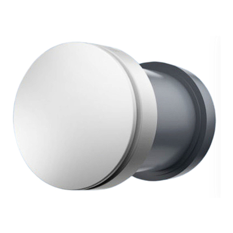
airmaster AM 50 Manual

0
Operation & Maintenance
AM 50
1·2

This manual features texts, illustrations, and drawings that may not be replicated or otherwise circulated, even as excerpts, without
express permission from Airmaster A/S.
Revision
Date
Description
1.0
2022-11-17
First edition.
IMPORTANT!
Read the manual thoroughly before using the product.
Keep this manual for later use.
Place of installation and serial number (S/N)
Type
Delivery date
Mounting location
S/N Air handling unit
S/N Cooling Module -

3/32
Table of content
1Introduction....................................................................................................................................................................................................................................5
1.1 Target group ........................................................................................................................................................................................................................5
1.2 Warning Symbols..............................................................................................................................................................................................................5
1.3 Liability.....................................................................................................................................................................................................................................5
2Safety instructions.....................................................................................................................................................................................................................6
2.1 Everyday use........................................................................................................................................................................................................................6
2.2 Maintenance ........................................................................................................................................................................................................................6
2.2.1 Electrical current.....................................................................................................................................................................................................6
2.2.2 Moving parts..............................................................................................................................................................................................................7
3Product Identification ..............................................................................................................................................................................................................8
3.1 Product name and type.................................................................................................................................................................................................8
3.2 Correct use ...........................................................................................................................................................................................................................8
3.3 Capacity ..................................................................................................................................................................................................................................8
3.4 Product information according to directive 2009/125EC......................................................................................................................8
3.5 Manufacturer.......................................................................................................................................................................................................................8
3.6 EU Declaration of Conformity...................................................................................................................................................................................9
3.7 Certificates ...........................................................................................................................................................................................................................9
3.8 Warranty.................................................................................................................................................................................................................................9
4The unit’s composition ......................................................................................................................................................................................................... 10
5Everyday use................................................................................................................................................................................................................................12
5.1 Turn on/off and regulation of the ventilation level....................................................................................................................................12
5.2 Choose the right ventilation step .........................................................................................................................................................................13
5.3 Emergency alert ..............................................................................................................................................................................................................14
5.4 Cleaning ............................................................................................................................................................................................................................... 16
5.4.1 Regular cleaning................................................................................................................................................................................................... 16
5.4.2 Thorough cleaning...............................................................................................................................................................................................17
5.5 Filter change .....................................................................................................................................................................................................................20
5.5.1 Filter change indicator .....................................................................................................................................................................................23
5.6 Function test.....................................................................................................................................................................................................................24
6Maintenance ...............................................................................................................................................................................................................................25
6.1 Maintenance schedule ...............................................................................................................................................................................................25
6.2 Cleaning the ventilation unit...................................................................................................................................................................................25
6.3 Troubleshooting .............................................................................................................................................................................................................29
Appendix A EU Declaration of Conformity .............................................................................................................................................................. 30
Appendix B Certificates.........................................................................................................................................................................................................31

4/32
Figures
Figure 1 - The units composition. Seen from the inside (left picture) and outside (right picture)................................................... 10
Figure 2 - The visible part (seen from inside) ................................................................................................................................................................... 10
Figure 3 - The air current from the unit................................................................................................................................................................................. 11
Figure 4 - The ventilation unit half out of the wall mount.......................................................................................................................................... 11
Figure 5 - Wall mount and the outside part........................................................................................................................................................................ 11
Figure 6 - Button for turning on/off and changing the ventilation step...........................................................................................................12
Figure 7 - Visual signal of the ventilation level seen on the “back wall” through the grille ..................................................................13
Figure 8 - Turn off the unit............................................................................................................................................................................................................14
Figure 9 - Plastic bag for sealing...............................................................................................................................................................................................14
Figure 10 - The plastic bag is used to cover the unit ................................................................................................................................................... 15
Figure 11 - Secure the bag with the rubber band........................................................................................................................................................... 15
Figure 12 - Cleaning of the visible internal part............................................................................................................................................................... 16
Figure 13 - Turn off the unit..........................................................................................................................................................................................................17
Figure 14 - Press down on the spring catches .................................................................................................................................................................17
Figure 15 - Take the ventilation system out and place it down on the internal cover............................................................................ 18
Figure 16 - Carefully vacuum the hole in the wall as well as the coarse filter in the back.................................................................... 18
Figure 17 - The ventilation unit is placed back in the wall......................................................................................................................................... 18
Figure 18 - Clean the internal coarse filter......................................................................................................................................................................... 19
Figure 19 - Reattach the internal cover ............................................................................................................................................................................... 19
Figure 20 - Turn off the unit........................................................................................................................................................................................................20
Figure 21 - Change the internal filter .....................................................................................................................................................................................20
Figure 22 - Press down on the spring catches.................................................................................................................................................................21
Figure 23 - Take the ventilation system out and place it down on the internal cover............................................................................21
Figure 24 - Changing the outside filter ................................................................................................................................................................................22
Figure 25 - The ventilation unit is placed back in the wall........................................................................................................................................ 22
Figure 26 - Resetting the filter indicator.............................................................................................................................................................................23
Figure 27 - Start the unit................................................................................................................................................................................................................24
Figure 28 - Turn off the unit........................................................................................................................................................................................................25
Figure 29 - Remove the internal filter...................................................................................................................................................................................26
Figure 30 - Press down on the spring catches...............................................................................................................................................................26
Figure 31 - Take the ventilation system out and place it down on the internal cover............................................................................26
Figure 32 - Remove the outside filter...................................................................................................................................................................................27
Figure 33 - Carefully clean the ventilation unit with compressed air ...............................................................................................................27
Figure 34 - Place a new outside filter in the ventilation unit ..................................................................................................................................28
Figure 35 - The ventilation unit is placed back in the wall .......................................................................................................................................28
Figure 36 - Place a new internal filter in the ventilation unit..................................................................................................................................28
Tables
Table 1 - Product name and type................................................................................................................................................................................................8
Table 2 - Capacity, sound pressure, nominal current.....................................................................................................................................................8
Table 3 - Adjusting the ventilation step................................................................................................................................................................................12
Table 4 - choosing the right ventilation step.....................................................................................................................................................................13
Table 5 - Overview of cleaning.................................................................................................................................................................................................. 16
Table 6 - Troubleshooting............................................................................................................................................................................................................29

5/32
1Introduction
This is an instruction manual for AM 50. Here you will find information concerning the operation and maintenance of
the unit. The full documentation package contains a Mounting manual and an Operation and Maintenance manual.
Both manuals are available at https://www.airmaster-as.com/en/
The manual should be passed along to and saved by the air handling unit’s owner.
1.1 Target group
This manual is addressed to both laypersons as well as qualified personnel.
1.2 Warning Symbols
This manual may contain warning symbols. The symbols adhere to the ISO7010 standard. The visual depiction may
vary depending on the type of media.
The symbols are described below:
DANGER
Danger to persons.
Failure to comply with the instruction results in severe or fatal injuries to persons.
WARNING
Danger to persons.
Failure to comply with the instruction can result in injuries to persons.
NOTICE
Avoiding material damage.
Failure to comply with the instruction can damage the device and/or its environment.
Information, tips, and recommendations.
1.3 Liability
The manufacturer cannot be held liable for damages, which occur due to usage in violation of this manual’s
instructions.
The manufacturer reserves the right to make changes without notice. All values stated are nominal values and may be
affected by local conditions.
The warranty is voided, should this manual not be followed.
Any repairs not carried out by Airmaster A/S will also void the warranty.

6/32
2Safety instructions
Follow this manual to ensure correct operation and maintenance. Should any doubts or uncertainty arise concerning
the contents of the manual, please contact Airmaster A/S, see section 3.5 on page 8 for contact information.
Only use the product for its described purposes.
2.1 Everyday use
Laypersons may use the unit in the following ways:
•Turn the unit on/off and change the ventilation steps on the unit using the button for this purpose.
•Clean the wall-mounted part of the unit and the coarse filter.
•Change the filters in the unit. However, it is recommended that qualified personnel replace filters as part of
the maintenance.
Should the unit stop working, the power needs to be switched off. Summon qualified personnel.
Laypersons may not carry out the maintenance of the unit. Additionally, testing, troubleshooting, and work with the
electrical system may only be carried out by trained personnel, who are specialized in electric equipment.
2.2 Maintenance
Maintenance must be carried out by qualified personnel. It is only trained personnel with specialization in electrical
equipment who can test, troubleshoot, and work with the electrical system.
Repairs must be done by Airmaster A/S.
2.2.1 Electrical current
DANGER
Voltage can give an electrical shock.
When work is being done on the unit, the voltage source must be switched off, and effort should be
made that it cannot accidentally be switched on again.
Take the right precautions with shielding if work is being done on a unit with voltage.
WARNING
Terminal blocks, terminals, and electrical connectors can carry voltage potential even when the unit
has been switched off.
Wait 5 minutes after disconnecting all the connections to the voltage source before touching the unit.
WARNING
The unit may automatically restart after power failure.

7/32
2.2.2 Moving parts
NOTICE
Loose objects, hair, and jewelry may get snagged on rotating parts and dragged into the unit
Do not wear jewelry or loose objects while working with rotating parts. Protect long hair by wearing
headgear.
NOTICE
Body parts that come in contact with rotating parts can suffer minor or moderate damage.
Avoid making unfavorable contact with the unit and make sure that all parts are stationary before
working on the unit.
Dropping the air handling unit can result in damage or injuries to humans or objects. If the unit is
removed from the wall, for example during cleaning, it should be placed carefully on the internal cover
on a level surface.

8/32
3Product Identification
3.1 Product name and type
Product name AM 50
Unit item number 9000050001
Type Decentral air handling unit. Stand-alone unit.
Table 1 - Product name and type
3.2 Correct use
AM 50 is a decentralized room-based air handling unit with heat recovery. AM 50 provides a balanced exchange of air
in living spaces and smaller rooms.
NOTICE
AM 50 is not designed for wet rooms or kitchens.
Should you wish to use the AM 50 in wet rooms or kitchens, the unit should be used in tandem with an
air exhaust system in compliance with existing building regulations.
3.3 Capacity
AM 50 has six ventilation steps. Table 2 below shows step, capacity, sound, and nominal current.
Step
Capacity [m3/h]
Sound pressure [dB(A)]
Nominal current [A]
1
15
25
0,05
2
21
30
0,06
3
28
35
0,08
4
37
40
0,10
5
46
45
0,13
6
59
50
0,19
Table 2 - Capacity, sound pressure, nominal current
AM 50 will automatically adapt its ventilation step to the desired interval based on the relative humidity in the room.
3.4 Product information according to directive 2009/125EC
Product information according to “Directive 2009/125/EC” can be found on our website.
Direct link: EU Documentation, choose ’Product Information According to DIRECTIVE 2009125EC’.
3.5 Manufacturer
Airmaster A/S, Industrivej 59, 9600 Aars.
Phone: (+45) 98 62 48 22
E-mail: info@airmaster.dk
Web site: www.airmaster.dk

9/32
3.6 EU Declaration of Conformity
EU Declaration of Conformity can be found in Appendix A on page 30. The most recent version is always available on
our website.
Direct link: EU Documentation, choose ’EU Declaration of Conformity’.
3.7 Certificates
AM 50 is Eco Label certified, please see Appendix B on page 31. The most recent version is always available on our
website.
Direct link: EU Documentation, choose ’Eco Labels’.
3.8 Warranty
The unit comes with a 24-month warranty, for further information see Terms of Sale and Delivery.
The warranty is voided if:
•Error messages are ignored.
•If the filters are not changed when the filter change identification flashes, or when this is not done according
to the manual.
•Instructions provided in this manual are not adhered to.

10/32
4The unit’s composition
The unit is comprised of a wall-mounted part along with a ventilation unit located inside the wall-mounted part. The
wall-mounted part has an outside and internal side.
The unit is shown in Figure 1 below:
Figure 1 - The units composition. Seen from the inside (left picture) and outside (right picture)
1. The internal cover which protects the air handling unit.
2. The visible part of the air handling unit. The air handling unit can only be seen from the inside.
3. Mount in the wall, this part is not visible.
4. The outside part of the wall mount. This is visible from the outside.
Pictured below in Figure 2, is what you will see when standing inside and looking at the wall. These are bullets 1 and 2
mentioned above.
Figure 2 - The visible part (seen from inside)
The grille at the top is where the inlet air is coming from. Figure 3 illustrates this.

11/32
Figure 3 - The air current from the unit
The ventilation unit inside the wall mount can be taken out, see Figure 4 below.
If the ventilation unit is taken fully out, you can see the wall mount and the outside part, see Figure 5 below.
Figure 4 - The ventilation unit half out of the wall mount
Figure 5 - Wall mount and the outside part
The ventilation unit is only taken out to conduct a thorough cleaning.

12/32
5Everyday use
Users may of course turn the air handling unit on/off and adjust the ventilation steps. You may also clean the wall-
mounted part of the unit. You may also change the filter, but we recommend that this is done by qualified personnel as
a part of the maintenance.
This section will give you instructions on the use of the unit as well as cleaning and filter change. Follow the
instructions closely.
5.1 Turn on/off and regulation of the ventilation level
The unit has a single button for turning on/off as well as adjusting the ventilation step. The button is located on top of
the unit, see Figure 6 below.
1. Touch the button to start. The unit will now start at the lowest ventilation step.
2. Should you require a higher ventilation step, touch the button one more time as it will jump up one ventilation
step for each button touch.
3. You turn off the unit completely by touching the button one more time after it is on ventilation step 6.
Figure 6 - Button for turning on/off and changing the ventilation step
Should you wish to start in for example ventilation step 4 from an off state, touch the button four times
in quick succession which will start the unit at step 4, see Table 3 below.
Off -
Step 1 1 button touch from off-state
Step 2 2 button touches in quick succession from off state, or 1 touch from step 1
Step 3 3 button touches in quick succession from off state, or 1 touch from step 2
Step 4 4 button touches in quick succession from off state, or 1 touch from step 3
Step 5 5 button touches in quick succession from off state, or 1 touch from step 4
Step 6 6 button touches in quick succession from off state, or 1 touch from step 5
Off 1 button touch from step 6, or the number of button touches to ‘off’ from the current step
Table 3 - Adjusting the ventilation step

13/32
Additionally, when you touch the button, you will see a visual signal showing the ventilation step: a green, flashing
diode, visible when looking down, through the grille behind the button, see Figure 7 below.
Figure 7 - Visual signal of the ventilation level seen on the “back wall” through the grille
A single button touch from an off state will make the diode flash once to show that the unit is in ventilation step 1 (the
flash will repeat after approx. 3 seconds, after which it turns off).
When you touch the button again, the diode will flash twice in quick succession (repeats approx. 3 seconds, after
which it turns off) to show that the unit is now in ventilation step 2. Ventilation step 3 gives three flashes, et cetera, up
to step 6.
5.2 Choose the right ventilation step
The ventilation step is dependent upon where the unit is located. As a baseline we recommend the following:
Step 1 15 m3/h Can be used in a bedroom for 1 person
Step 2 21 m3/h Can be used in a quiet office/housing for 1 person
Step 3 28 m3/h Can be used in a 1- or 2-person(s) office
Step 4 37 m3/h Can be used in a printer room, file room, basement room, or similar where a greater
exchange of air is desirable. Not recommended for rooms with long-term habitation.
Step 5 46 m3/h
Step 6 59 m3/h
Can be used when a boost of fresh air is necessary. Not recommended for rooms with
long-term habitation.
Table 4 - choosing the right ventilation step

14/32
5.3 Emergency alert
An emergency alert can mean that all ventilation will need to be turned off, e.g., if a fire close by generates toxic
smoke. Should this be the case, the unit will need to be switched off and sealed with a bag. The unit comes with a
plastic bag designed specifically for this purpose.
1. Turn the unit off by touching the button on top until it turns off, see Figure 8 below.
Figure 8 - Turn off the unit
2. Remove the internal cover and take out the plastic bag, which is rolled up tight and located in a little pocket to
the right, see Figure 9 below.
Figure 9 - Plastic bag for sealing
3. Reattach the internal cover.
4. Unfold the plastic bag and place it over the unit and secure it using the enclosed rubber band, see Figure 10
and Figure 11 on the next page.
The bag must cover the grille so pull it all the way to the wall. Put the rubber band as close to the wall as
possible.

15/32
Figure 10 - The plastic bag is used to cover the unit
Figure 11 - Secure the bag with the rubber band
5. The unit is now sealed.
After the emergency announcement is canceled, remove the plastic bag, fold it up, and return it to the small pocket
under the internal cover. Remember the rubber band.
The unit can now be turned on again.

16/32
5.4 Cleaning
To ensure optimal performance, it is necessary to regularly clean the unit. Apart from the regular cleaning, it is
necessary to perform a thorough cleaning, at the minimum, every six months whereby the ventilation unit is pulled out
and the hole in the wall is cleaned.
All cleaning is done from inside the building.
Daily/weekly/monthly
(depending on where the unit is mounted)Regular cleaning of the visible internal part.
Minimum every six months Thorough cleaning, possibly in conjunction with filter change
Table 5 - Overview of cleaning
5.4.1 Regular cleaning
The visible internal part of the unit can be wiped down with a damp, wrung-out rag as part of the regular cleaning. See
Figure 12 below.
Use water or a mix of water and all-purpose cleaning soap. Please make sure that the rag is wrung out as drops of
liquid may not enter the unit (through the grille at the top).
You may also use a feather duster or a vacuum cleaner to remove dust.
It is not necessary to turn off the unit for regular cleaning.
Figure 12 - Cleaning of the visible internal part

17/32
5.4.2 Thorough cleaning
The thorough cleaning can conveniently be combined with a filter change, see section 5.5 on page 20.
NOTICE
Please keep in mind that the unit weighs approx. 9 kg when removed from the wall.
1. Start by turning off the unit, see Figure 13 below. Wait 3 minutes until the unit has stopped rotating
completely.
Figure 13 - Turn off the unit
2. Press down on the spring catches to make them release, see Figure 14 below.
Figure 14 - Press down on the spring catches
3. Carefully pull the ventilation unit out of the wall and place it with the internal cover down on a level surface,
e.g., a table or the floor, see Figure 15.
It is important to place it on a level surface to avoid it falling over.

18/32
Figure 15 - Take the ventilation system out and place it down on the internal cover
4. Carefully vacuum the hole in the wall to remove dust and any dirt. Be especially attentive to the part furthest
in the back where the outside coarse filter is located, see the arrows in Figure 16 below.
Figure 16 - Carefully vacuum the hole in the wall as well as the coarse filter in the back
5. Place the ventilation unit back in the wall, and carefully press it all the way in until the spring catches make a
click, see Figure 17 below.
Figure 17 - The ventilation unit is placed back in the wall

19/32
6. Detach the internal cover. Remove the coarse filter and carefully clean it with a damp sponge or rag, see
Figure 18 below.
Use water or a mix of water and all-purpose cleaning soap for the cleaning.
Reattach the coarse filter.
Figure 18 - Clean the internal coarse filter
7. Reattach the internal cover, see Figure 19 below.
Figure 19 - Reattach the internal cover
8. The unit is now clean. Now you need to do a function test to make sure that everything is working as it should
See section 5.6 on page 24 for further information.
9. Once you have conducted a function test, you can set the desired ventilation step.

20/32
5.5 Filter change
The unit has two filters which need to be changed every six months to maintain good air quality. The filters are located
in front and behind the ventilation unit respectively. Both filters can be changed from the inside, so you do not have to
go outside to change them.
You can conveniently combine the filter change with the thorough cleaning, see section 5.4.2 on page 17.
NOTICE
Please keep in mind that the unit weighs approx. 9 kg when removed from the wall.
Make sure to have two new filters ready before starting. You CANNOT reuse them. You must use new
filters when changing the filters.
1. Start by turning off the unit, see Figure 20 below. Wait 3 minutes until the unit has stopped rotating
completely.
Figure 20 - Turn off the unit
2. Remove the internal cover. Take out the old filter and remove any dirt with a dry rag, see Figure 21 below. The
spent filter can be disposed of as household waste.
Replace the old filter with a new one. Be careful that the smooth side of the filter is placed facing the
ventilation unit. Reattach the internal cover.
Figure 21 - Change the internal filter
Other manuals for AM 50
1
Table of contents
Other airmaster Fan manuals
Popular Fan manuals by other brands

Helios
Helios KWL EC 220 D Eco R Installation and operating instructions

Perel
Perel TV76502 user manual

Matrix
Matrix FE-70D3fOL(E) owner's manual

Westinghouse
Westinghouse 72161 instructions

Monte Carlo Fan Company
Monte Carlo Fan Company 5RH52 Series owner's manual

Kichler Lighting
Kichler Lighting Kittery Point instruction manual