airnet AIR-PTP600S User manual

Page 1 of 81

Page 2 of 81
© Copyright 2009 Netkrom
Technologies Inc.
All Rights Reserved
This document contains information, which is protected by copyright. Reproduction,
adaptation or translation without prior permission is prohibited, except as allowed under the copyright
laws.
Trademark
Information
Netkrom® is a registered trademark of Netkrom Technologies, Inc. Microsoft Windows and the Windows
logo are the trademarks of Microsoft Corp. NetWare is the registered trademark of Novell Inc. WMM and
WPA are the registered trademarks of Wi-Fi Alliance. All other brand and product names are
trademarks or registered trademarks of their respective owners.
Notice: Copyrights © 2009 by Netkrom Technologies, Inc. All rights reserved. Reproduction, adaptation,
or translation without prior permission of Netkrom Technologies, Inc. is prohibited, except as allowed
under the copyright laws.
Disclaimer
Netkrom Technologies, Inc. provides this manual without warranty of any kind, expressed or implied,
including but not limited to the implied warranties of merchantability and fitness for a particular purpose.
Netkrom Technologies, Inc. may make improvements and/or changes to the product and/or
specifications of the product described in this manual, without prior notice. Netkrom Technologies, Inc
will not be liable for any technical inaccuracies or typographical errors found in this guide. Changes are
periodically made to the information contained herein and will be incorporated into later versions of the
manual. The information contained is subject to change without prior notice.

Page 3 of 81
FCC NOTICE
This device has been tested and found to comply with the limits for a Class B digital device, pursuant to
Part 15 of the FCC Rules. These limits are designed to provide reasonable protection against harmful
interference in a residential installation. This device generates uses and can radiate radio frequency
energy and, if not installed and used in accordance with the instructions, may cause harmful interference
to radio communications. However, there is no guarantee that interference will not occur in a particular
installation. If this device does cause harmful interference to radio or television reception, the user is
encouraged to try to correct the interference by one or more of the following measures:
•
Reorient or relocate the receiving antenna.
•
Connect the computer to an outlet on a circuit different from that to which the receiver is
connected.
•
Increase the separation between the computer and receiver.
•
Consult the dealer or an experienced radio/TV technician for help.
Caution: Any changes or modifications not expressly approved by the grantee of this device could
void the user's authority to operate the equipment.
FCC Compliance Statement: This device complies with Part 15 of the FCC Rules. Operation is
subject to the following two conditions:
This device may not cause harmful interference, and
This device must accept any interference received, including interference that may cause undesired
operation.
RF Exposure warning
The equipment complies with FCC RF exposure limits set forth for an uncontrolled environment. The
equipment must not be co-located or operating in conjunction with any other antenna or transmitter.
ICES 003 Statements
This Class B digital apparatus complies with Canadian ICES-003.

Page 4 of 81
Declaration of Conformity
Netkrom Technologies, Inc. declares the following:
Product Name: AIRNET 300Mbps 4.9/5.8 GHz MIMO Bridge Point to Point Kit
Model No.: AIR-PTP600 conforms to the following Product Standards:
This device complies with the Electromagnetic Compatibility Directive (89/336/EEC) issued by the
Commission of the European Community. Compliance with this directive implies conformity to the
following European Norms (in brackets are the equivalent international standards.)
Electromagnetic Interference (Conduction and Radiation): EN 55022 (CISPR 22)
Electromagnetic Immunity: EN 55024 (IEC61000-4-2, 3, 4, 5, 6, 8, 11)
Low Voltage Directive: EN 60 950: 1992+A1: 1993+A2: 1993+A3: 1995+A4: 1996+A11: 1997.
Therefore, this product is in conformity with the following regional standards: FCC Class B:
following the provisions of FCC Part 15 directive, CE Mark: following the provisions of the EC directive.
Netkrom Technologies, Inc. also declares that:
The wireless card in this product complies with the R&TTE Directive (1999/5/EC) issued by the
Commission of the European Community. Compliance with this directive implies conformity to the
following:
EMC Standards: FCC: 47 CFR Part 15, Subpart B, 47 CFR Part 15, Subpart C (Section 15.247); CE:
EN 300 328-2, EN 300 826 (EN 301 489-17)
Therefore, this product is in conformity with the following regional standards: FCC Class B:
following the provisions of FCC Part 15 directive, CE Mark: following the provisions of the EC directive.
Manual Version: 2.08c (September 2010)
This manual is written based on Firmware version 2.00

Page 5 of 81
Table of Contents
Overview the Product..................................................................................................7
Introduction..................................................................................................................7
Features and Benefits................................................................................................................8
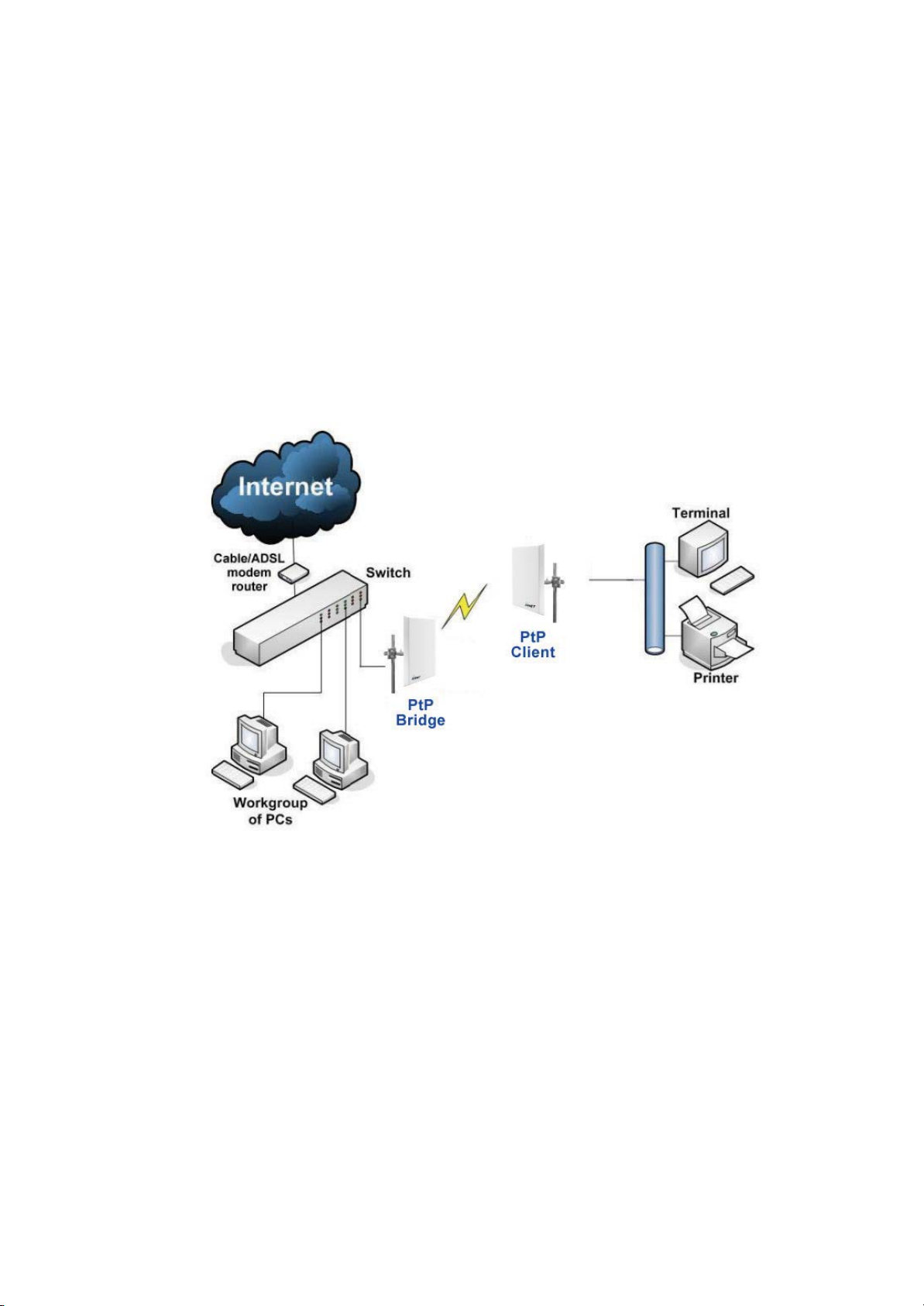
Operation Modes and Connection Examples............................................................................9
Hardware Installation ...............................................................................................14
Package Contents....................................................................................................................14
Setup Requirements ................................................................................................................15
AIRNET MIMO Outdoor Bridge Point to Point Installations ................................................16
Mounting AIRNET MIMO Outdoor Bridge in the pole or tower...........................................19
Access the Web Interface...........................................................................................24
Access with uConfig...............................................................................................................24
Access with a Web Browser....................................................................................................27
Navigation...................................................................................................................29
Main Menu Bar.......................................................................................................................29
How to save changes...............................................................................................................29
Basic Network Tab.....................................................................................................30
Network Mode: Bridging and Routing ...................................................................................30
LAN Setup..............................................................................................................................30
Basic Wireless Tab......................................................................................................33
Basic Wireless Settings...........................................................................................................33
Access Point Parameters Settings ...........................................................................................35
Station Parameters Settings.....................................................................................................37
Wireless Security ....................................................................................................................39
Virtual Access Point (VAP).....................................................................................................44
Advance Wireless Tab................................................................................................45
Long Range Parameters Setup................................................................................................45
Advanced Network Tab.............................................................................................47
Spanning Tree Setup ...............................................................................................................48
NAT Setup...............................................................................................................................48
Firewall Setup.........................................................................................................................50
Multicast Routing Setup..........................................................................................................51
Remote Management Setup ....................................................................................................51
UPNP:.....................................................................................................................................51
Services Tab................................................................................................................52
Ping Watchdog........................................................................................................................53
Auto-Reboot............................................................................................................................53
SNMP Setup............................................................................................................................54
NTP Setup...............................................................................................................................54
Web HTTP Security................................................................................................................54
TelnetAccess Setup.................................................................................................................55
SSH AccessSetup...................................................................................................................55
System Log Setup ...................................................................................................................55

Page 6 of 81
System Tab..................................................................................................................56
Firmware Upgrade ..................................................................................................................56
Host Name ..............................................................................................................................57
Administrative and Read-onlyAccount..................................................................................57
Configuration Management ....................................................................................................58
Device Maintenance................................................................................................................58
Status Page..................................................................................................................59
Clients Connection Status in AP Status Info...........................................................................61
Station Connection Info ..........................................................................................................62
Status Info ...............................................................................................................................62
More Status .............................................................................................................................64
VLAN Tab...................................................................................................................65
VLAN Switch .........................................................................................................................65
VLAN Management................................................................................................................66
Appendix I - Network................................................................................................67
Appendix II – Wireless with Router Mode..............................................................70
Appendix III-Advanced Settings .............................................................................75
Appendix IV- Services ...............................................................................................78
Appendix V- VLAN Setup examples........................................................................80
A) Tagged Wireless VLAN to Tagged Ethernet VLAN Setup................................................80
B) Untagged Wireless VLAN to Tagged Ethernet VLAN setup.............................................81
C) Tagged VLAN Pass-Through.............................................................................................81

Page 7 of 81
Overview the Product
Introduction
The AIRNET 300 Mb 4.9-5.8GHz MIMO Bridges Point to Point kit is an optimal solution
for a large number of applications. In its simplest form, it can be deployed by many
organizations to provide Ethernet extensions (i.e. LAN-to-LAN) between two locations. In
its most advanced configurations, the AIRNET 300Mb 4.9-5.8GHz MIMO Bridge Point
to Point kit is able to provide a complete infrastructure that enables companies of all sizes
to connect their remote sites to the headquarters, thus allowing the simultaneous
transmission of multi-protocol services such as voice, video and data. This family of
solutions can also be deployed by mobile operators requiring multi-megabit capacity for
their backhaul links.
The AIRNET 300Mb 4.9-5.8GHz MIMO Bridge Point to Point kit operates in the 5.1 to
5.8 GHz Unlicensed Frequency Band and 4.9GHz Public Safety Band, and comes
complete with a set of accessories to ease outdoor installations. As the most cost
effective point to point solution from AIRNET family, any deployment will enjoy a quick
return on investment.
The AIRNET 300Mb 4.9-5.8GHz MIMO Bridge Point to Point kit is the
easiest toinstall family of broadband wirelessbridges on the market.
To protect your security and privacy, the AIRNET 300Mb 4.9-5.8GHz MIMO Bridge Point
to Point kit is armed with many enhanced and latest wireless security features such
as IEEE 802.11i standards, MAC Address Filtering, IEEE 802.1x Authentication and
64/128-bit WEP (Wired Equivalent Privacy) to ensure privacy within the same wireless
network.
The AIRNET 300 Mb 4.9-5.8GHz MIMO Bridges Point to Point kit also incorporates a
unique set of advanced features such as: Long-Range parameter fine-tuning which
provide the access point with the ability to auto-calculate parameters such as slot time,
ACK time-out and CTS time-out to achieve a longer range.
Depending on the model, some model will have less hardware features. All the software functions
are the same.

Page 8 of 81
Features and Benefits
Point-to-Point Support
Point-to-Point communication between different buildings enables you to bridge wireless
clients while unifying the networks.
Highly Secured Wireless Network
The AIR-PTP6000L supports the highest available wireless security standard:
IEEE802.11i compliant. The AIR-PTP6000L also supports IEEE 802.1x for secure and
centralized user-based authentication. Wireless clients are thus required to authenticate
through highly secure methods like EAP-TTLS and EAP-PEAP, in order to obtain access
to the network.
uConfig Utility
The exclusive uConfig utility allows users to access the user-friendly Web configuration
interface of the access point without having to change the TCP/IP setup of the
workstation.
HTTPS
The AIR-PTP6000L supports HTTPS (SSL) in addition to the standard HTTP.
HTTPS (SSL) features additional authentication and encryption for secure
communication.
Telnet
Telnet allows a computer to remotely connect to the access point CLI (Command
Line Interface) for control and monitoring.
SSH
SSH (Secure Shell Host) establishes a secure host connection to the access point
CLI for control and monitoring.

Page 9 of 81
Operation Modes and Connection Examples
Access Point and Access Point WDS Mode
The Access Point Mode is the default mode of the AIR-PTP600. It enables the bridging of
wireless clients to wired network infrastructure and enables transparent access and
communication with each other.
The illustration below shows a typical resources sharing application example using this
device. The wireless users are able to access the file server connected to the switch,
through the AIR-PTP600 in Access Point Mode.
Access Point WDS Mode
This operating mode is generally used for point-to-point or point-to-multi-point connection.
It is mainly used with Station WDS to build the point and multi-point connections.

Page 10 of 81
Station Mode
In Station mode the AIR-PTP600 acts as a wireless client.
When connected to an access point, it creates a network link between the Ethernet
network connected at the AIR-PTP600, and the wireless Ethernet network connected at
the access point.
In this example the workgroup PCs on the Ethernet network connected to the Station
device can access the printer across the wireless connection to the access point where the
printer is connected.

Page 11 of 81
Station WDS Mode
Station WDS mode is similar to Station mode. The difference is that Station WDS
must connect to an access point configured as Access Point WDS mode.
Station WDS is mainly used for point-to–point connection between 2 buildings or
locations as far as several kilometers away.
Point-to-Point Point-to-MultiPoint
An access point setup as Access Point WDS
and other as Station WDS. An access point setup as Access Point WDS
and several other devices as Station WDS.
This mode is generally used for outdoor connections over long distances, or for indoor
connections between local networks.

Page 12 of 81
Router Mode
In Router Mode, the AIR-PTP600 also operates as a router.
Either the wireless or Ethernet can be setup as WAN connection to a broadband modem.
Wireless as WAN is known as Station + Router mode and Ethernet as WAN is known as
AP + Router mode. The AIR-PTP600 supports several types of broadband connections
Static IP, Dynamic IP and PPPoE. For setup details refer to the respective section.
Station + Router connection example
Wireless is used to connect to the broadband (WAN).
Ethernet is the local network (LAN)
sharing the Broadband connection.
AP + Router connection example
Ethernet is use to connect to the
broadband (WAN).
Wireless is the local network (LAN)
sharing the broadband connection.
Broadband Internet Access Type:
Static IP Address
Use Static IP Address you have subscribed a fixed IP or range IP addresses from your
ISP.
Dynamic IP Address
With Dynamic IP Address the device automatically request IP address from
modem or ISP.
PPP over Ethernet (PPPoE)
When using ADSL services provided by your ISP support PPPoE connection.

Page 13 of 81
Repeater WDS Mode
Repeater WDS Mode is mainly used to extend the wireless range and coverage of the
wireless network allowing access and communications over places generally difficult for
wireless clients to connect to the network.
In Repeater mode, the AIR-PTP600 acts as a relay for network signals on the network by
regenerating the signals it receives, and retransmitting them to main network
infrastructure.
Detailed information on the Repeater mode is available in the Repeater Setup section.
** Note: Repeater WDS requires the access point to be setup in
Access Point WDS mode to work.

Page 14 of 81
Hardware Installation
Package Contents
Take a moment to ensure you have all of the following parts in your AIRNET
300Mbps 4.9/5.8 GHz MIMO Bridge Point to Point Kit installation kit before you
begin installing the product. If any parts are missing, please contact your local vendor or
contact us at 305-4182232.
1 5
6
3
4
7
2
KIT CONTAINS
1. Two AIRNET 300Mbps 4.9/5.8 GHz MIMO Bridge Units
2. Two Mounting brackets (include: 2 Wall/ Pole mounting system and4screw nuts
3. Two PoE Injector
4. Two Power Cables
5. Two RJ45 Waterproof Connector System
6. CD ROM
7. Two 75’Outdoor Rated CAT5e shielded cables

Page 15 of 81
Setup Requirements
•
CAT5/5e Networking Cable.
•
At least 1 computer installed with a web browser and a wired or wireless
network interface adapter.
•
All network nodes installed with TCP/IP and properly configured IP address
parameters.
Important!
•
Configure and verify the AIRNET MIMO Outdoor Bridge kit operations first
before you mount the unit in a remote location.
•
You may need to install a lightning arrestor to protect your AIRNET MIMO
Outdoor Bridge kit from the lightning.
•
For choosing the best location for your AIRNET MIMO Outdoor Bridge
choose an elevated location where trees, buildings and large steel structures will
not obstruct the antenna signals and which offers maximum line-of-sight
propagation with the users.

Page 16 of 81
AIRNET MIMO Outdoor Bridge Point to Point Installations
The diagram below shows the overall setup of AIRNET MIMO Outdoor Bridge unit.

Page 17 of 81
S
St
te
ep
p 1
1:
:
Connect your UTP or FTP Outdoor cat.5 Ethernet cable with waterproof connector to the RJ-45
connector on the AIRNET MIMO Outdoor Bridge unit. Then connect the other end of the cable to
the PoE injector.
For the Netkrom PoE, the recommended length of the RJ45 Category 5 cable is up to 150 feet or
50 meters.
1.- Remove the thin enclosure nut from
the feedthru assembly. This can be
discarded. Loosen the compression nut
completely
2.- Insert the RJ45 connector thru
the feedthru assembly
feedthru
assembly
enclosure nut
3.- Tighten the compression nut loosely to
the feedthru assembly
compression
nut
4.- Screw the entire feedthru assembly
into the RJ45-ECS housing which is
already mounted in the AIRNET MIMO
Outdoor Bridge unit. There should be a
rubber gasket between the two
assemblies. Tighten the
feedthru assembly to create a seal.
RJ45-ECS housing
5.- The final step is to tighten the
compression nut until the gaskets are
tight around the Cat5 cable.Always
push the cable toward the connector
while tightening to ensure good strain
relief of cable to connector.

Page 18 of 81
S
St
te
ep
p 2
2:
:
From the PoE injector connect one cat.5 Ethernet cable to the AIRNET MIMO Outdoor
Bridge unit and another cat.5 cable to a switch or PC.
S
St
te
ep
p 3
3:
:
Connect the power cable supplied in the Netkrom PoE kit to the main electrical supply and the
power plug into the socket of the injector.
Now, turn on your power supply. Notice that the POWER LED has lighted up.
This indicates that the AIRNET MIMO Outdoor Bridge is receiving power through the Netkrom
PoE Injector and that connection between your AIRNET MIMO Outdoor Bridge unit and your
network has been established.
Note:
Please use the PoE injector provided in the package. Using a PoE with a different voltage rating
will damage this product.

Page 19 of 81
Mounting AIRNET MIMO Outdoor Bridge in the pole or tower
Netkrom AIRNET MIMO Outdoor Bridge device can be mounted on the pole or tower
as shown in following:
1.- Attach the mounting bracket to the back of the radio using
the four hex screws provided. (Do not over tighten the screws.)
Note: The bracket in the illustration side shows the normal
orientation which allows the wireless unit to be pointed up towards
the base station antenna. However, if you live somewhere that
would require you pointing the device down towards the base
station antenna (for example, you are on the side of a mountain in
view of the base station antenna below), reverse the bracket so
the Netkrom wireless radio Unit can be
“tilted” downward when you aim theAIRNET MIMO Outdoor Bridge
in a later step.
2.-You can use the pipe bracket assembly for either thin or thick
poles by just inverting the position of one of the elements as it
shown on the right.
3.- Mount theAIRNET MIMO Outdoor Bridge to the top of the
pipe or other support and point the AIRNET MIMO Outdoor
Bridge in the approximate direction of the base station antenna,
then hand-tighten the nuts on the mounting system.

Page 20 of 81
Configure the IPAddress
After setting up the hardware you need to assign an IP address to your PC so that it is in
the same subnet as the access point.
For Windows 95/98/98SE/ME/NT
S
St
te
ep
p 1
1:
:
From your desktop, right-click the Network Neighborhood icon and select Properties.
S
St
te
ep
p 2
2:
:
Select the network adapter that you are using, then right-click and select Properties.
S
St
te
ep
p 3
3:
:
Highlight TCP/IP and click on the Properties
button.
S
St
te
ep
p 4
4:
:
Select the Specify an IP address radio button.
Set the IP address to 192.168.168.X and
subnet mask to 255.255.255.0, where X can be
any number from 2 to 254.
This manual suits for next models
1
Table of contents