Aironet UC3500 User manual

Aironet Wireless Communications, Inc. • 3875 Embassy Parkway
Akron, Ohio 44333-8357
www.aironet.com
User’s Guide
Clients for Ethernet or Serial
Products supported:
UC3500, MC3500
DOC-710-004236-B0

AironetWireless Communications, Inc.
No part of this document may be reproduced or transmitted in any means, elec-
tronic or mechanical, for any purpose, without the written permission of Aironet.
Information in this document is subject to change without notice.Aironet makes
no representation or warranties with respect to the contents of this manual and
specifically disclaims any express or implied warranties of merchantability or
fitness for any particular purpose.
© 1999 Aironet Wireless Communications, Inc.
All rights reserved.
LM3500
TM
, AP3500
TM
, PC3500
TM
, MC3500
TM
, UC3500
TM
, ISA3500
TM
, PCI3500
TM
,
BR100
TM
, BR500
TM
, BRE100
TM
, BRE500
TM
, and Aironet
TM
are trademarks of
Aironet Wireless Communications, Inc.
Other trademarks used are properties of their respective owners.
Printed in USA
DOC-710-004236-B0

Table of Contents
Introduction ........................................................ 1-1
Purpose of the Manual .................................. 1-2
Serial Client ................................................... 1-3
Ethernet Client .............................................. 1-6
Universal Client ...................................... 1-6
Multi-Client .............................................. 1-7
Safety Information ......................................... 1-8
Dipole Antenna ....................................... 1-9
High Gain Antennas ............................... 1-9
Other Devices in the Wireless
Infrastructure .......................................... 1-9
Before You Start .......................................... 1-10
Terminology ................................................ 1-11
Installation .......................................................... 2-1
Installing the Antenna .................................... 2-1
Installing the Console Port Cable .................. 2-2
Installing the Ethernet Connection ................ 2-3
Attaching the AC/DC Power Pack
and Powering On .......................................... 2-4
Viewing the Indicator Displays ...................... 2-5
Top Panel Indicators ............................... 2-5
Back Panel Indicators (Ethernet Only) ... 2-8
Using the Mounting Bracket .......................... 2-9
Configuration ..................................................... 3-1
Accessing the Console System ..................... 3-1
Configuring the Aironet Wireless Client ........ 3-4
SSID Identifier (SSID) ............................. 3-4
Verifying Association .............................. 3-4
Configuring the Port ................................ 3-5
Disconnecting the Terminal ........................... 3-7
Ethernet Client ........................................ 3-7
Serial Client ............................................ 3-7

Appendix A .........................................................A-1
DC Power Jack Connector ............................A-1
Appendix B .........................................................B-1
Serial Port Pinout ..........................................B-1
Ethernet RJ-45 Port Pinout ...........................B-2
Sample Application Cable Pinout ..................B-3
Appendix C..........................................................C-1
Manufacturers Federal Communication
Commission Declaration of Conformity
Statement.......................................................C-1
Department of Communications–Canada
European Telecommunications Standards
Institute Statement of Compliance
Information to User.........................................C-4
Declaration of Conformity...............................C-5
Appendix D .........................................................D-1
Technical Support .........................................D-1
Technical Reference Manual ..................D-1
Communications .....................................D-1
Web Site .................................................D-1

Introduction
1-1
Introduction
The Wireless Client from Aironet is another member of the
company’s broad array of wireless LAN solutions.Aironet
has pioneered the design and manufacture of wireless LAN
products that use advanced spread spectrum radio technol-
ogies for reliable data communications.
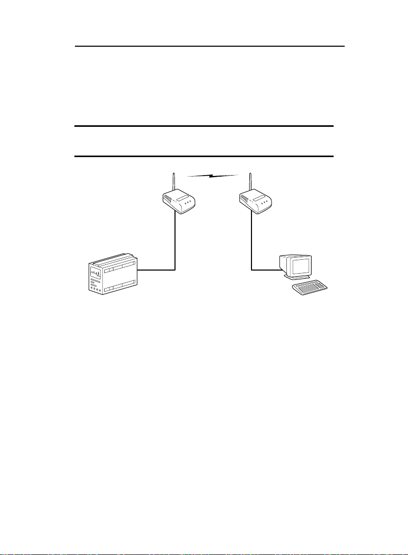
By using RF technology to rapidly send and receive data
over the airwaves, Aironet’s wireless LAN products enable
portable and mobile users to access all the resources of a
wired infrastructure without sacrificing roaming and mobility
capabilities.These wireless users enjoy network connectiv-
ity with the “real-time” speed and response that users have
come to expect from wired LANs.The mobility and portabil-
ity of Aironet’s wireless LAN products has spurred imple-
mentation among many vertical markets – including retail,
health care, manufacturing, and distribution.
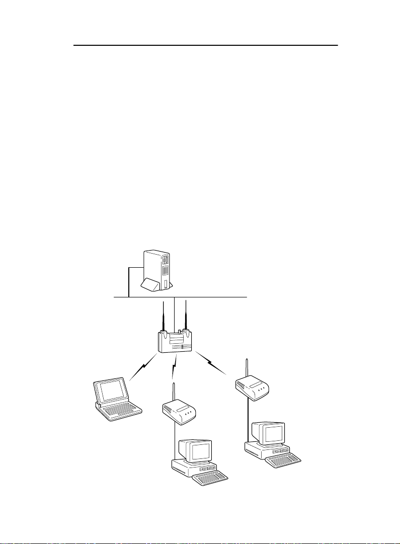
The Aironet Wireless Client system is compliant with IEEE
802.11 standards for wireless LAN. Compliance with this
standard provides assurance of technical excellence as well
as capability of interoperability with products from other
wireless vendors.
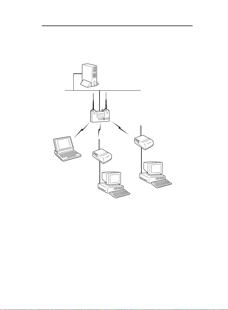
All Aironet products include the company’s patented soft-
ware architecture that enables users to roam seamlessly
between Access Points without losing infrastructure con-
nections.This exclusive software also provides load balanc-
ing, easy network expansion, and advanced power
management for battery-powered mobile devices.Aironet’s
array of wireless LAN solutions (including Access Points,
Bridges, Adapters, PC Cards, Universal Clients, antennas,
and infrastructure management software) enables you to
experience infrastructure performance while enjoying the
mobility and portability of wireless communications.

Introduction
1-2
Purpose of the Manual
The purpose of this User’s Guide is to allow you to easily
install and configure your Aironet Wireless Client.
For detailed technical and configuration procedures, see
the Technical Reference Manual document number
710-004237.
The Aironet Wireless Client is a small, stand-alone unit that
provides a wireless infrastructure connection for a device
that is unable to use a standard wireless LAN adapter. A
Wireless Client-equipped peripheral device is able to estab-
lish radio connections with any Aironet Access Point (Ether-
net and/or Token Ring models) or devices equipped with
Aironet wireless products installed throughout a facility. The
Multi-Client can connect up to four end nodes to an Ether-
net infrastructure.
For greater installation and application flexibility, Aironet
Wireless Clients are offered with a choice of radio frequen-
cies and interfaces.The Aironet Wireless Client offers radio
communications to 2.4 GHz frequency hopping compliant
with IEEE 802.11 specifications.
There are two interface options:
• Serial Universal Client
• Ethernet Universal Client or Multi-Client

Introduction
1-3
Serial Client
The Serial Client has a standard EIA-232-E port for use
with a wide range of devices that support standard serial
input/output. Many serial devices such as point-of-sale reg-
isters, weigh stations, and printers cannot support wireless
LAN cards, however they can be connected using a Wire-
less Client serial connection.The Wireless Client’s Serial
Port connects directly to the device’s Serial Port.This allows
the device to communicate with the infrastructure or
another computer over a wireless radio link.The Serial Cli-
ent appears as a serial node in the infrastructure. It routes
packets from the wired LAN to remote workstations, such
as PCs and handhelds, on the radio network.
The Serial Client can provide wireless data communication
between:
• A Wired LAN and fixed, portable, or mobile devices that
each contain a radio.
• A single client on a remote serial LAN and other nodes
in a wired LAN.
• A Single EIA-232-E serial device connected to a Wire-
less Client Serial Port and another serial device or host
computer connected to another Wireless Client.

Introduction
1-4
There are two common applications for the Serial Client:
• Replacing a serial cable with a wireless link.The cable
between a serial device and its host can be eliminated.
NOTE: For this application, two Wireless Clients are
required.
Serial
Universal
Client
Serial
Universal
Client
Terminal connected
via EIA-232-E
EIA-232-E Device

Introduction
1-5
• Connecting a serial device to a LAN using an Access
Point.
File Server
Wired LAN
Access Point
Station with
Radio Card End Node
Serial
Universal
Client
Serial
Universal
Client
End Node

Introduction
1-6
Ethernet Client
The Universal Client and the Multi-Client can connect
nodes to an Ethernet infrastructure.
Universal Client
The Ethernet Client connects to a standard Ethernet
port using a 10BaseT/RJ-45 (twisted pair) connector.
The Ethernet Client supports ad hoc networking or
Ethernet connectivity to a wired LAN using Access
Points.The Ethernet Client can be used in a variety of
infrastructure system configurations.The figure below
shows Ethernet Universal Clients connected to a file
server over a wired LAN through the Access Point.
File Server
Wired LAN
Access Point
Station with
Radio Card End Node
Ethernet
Universal
Client
Ethernet
Universal
Client
End Node

Introduction
1-7
Multi-Client
The Multi-Client connects to a standard 10BaseT/RJ-45
(twisted pair) connector.The Multi-Client can connect
up to four end nodes through a hub to an Ethernet infra-
structure.
Workstation Workstation
Multi-Client
Hub
Workstation
Mobile
Workstation
Access Point
(Root Unit)
File Server
Wired LAN

Introduction
1-8
Safety Information
The FCC with its action in ET Docket 96-8 has adopted a
safety standard for human exposure to radiated frequency
(RF) electromagnetic energy emitted by FCC certified
equipment.The Aironet products meet the uncontrolled
environmental limits found in OET-65 and ANSI C95.1,
1991. Proper operation of this radio according to the
instructions found in this manual will result in the user
exposure to be substantially below the FCC recommended
limits.
• Do not touch or move antenna(s) while the unit is
transmitting or receiving.
• Do not hold any component containing the radio such
that the antenna is very close or touching any exposed
parts of the body, especially the face or eyes, while
transmitting.
• Do not operate a portable transmitter near unshielded
blasting caps or in an explosive environment unless it
is a type especially qualified for such use.
• Do not operate radio or attempt to transmit data unless
the antenna is connected, if not, the radio may be
damaged.
LISTED
UL
®
®

Introduction
1-9
Dipole Antenna
Always orient antenna such that it is at least 15 cm
(6 inches) away from your body.
High Gain Antennas
High gain wall mount or mast mount antennas are
designed to be professionally installed and should be
located at a minimum distance of 30 cm (12 inches) or
more from your body. Please contact your professional
installer, VAR, or antenna manufacturer for proper
installation requirements.
Other Devices in theWireless Infrastructure
Refer to the User’s Guide and Technical Reference
Manual for the Access Point, Universal Client, PC Card,
or Bridge for additional information.

Introduction
1-10
BeforeYou Start
After unpacking the system, make sure the following items
are present and in good condition.
• Aironet Wireless Client (Universal Client or Multi-Client)
• Power Pack.The power pack will be either 120VAC/
60Hz or 90-264VAC/47-63Hz to 12-18VDC, whichever
is appropriate for country of use.
• Standard RP-SMA 2 dBi dipole antenna
• Mounting Kit
If any item is damaged or missing, contact your Aironet
supplier. Save all shipping and packing material in order to
repack the unit should service be required.
NOTE: Any remote antennas or associated coaxial
cables are ordered and packed separately.

Introduction
1-11
Terminology
When configuring your system, and when reading this
manual, keep in mind the following terminology:
Association
– Each root unit or repeater in the infrastruc-
ture contains an association table that controls the routing
of packets between the Access Point and the wireless infra-
structure.The association table maintains entries for all the
nodes situated below the Access Point on the infrastructure
including repeaters and client nodes.
End Node
– A client node that is located at the end of the
Network Tree.
Infrastructure
– The wireless infrastructure is the
communications system that combines Access Points,
mobile nodes, and fixed nodes. Access Points within the
infrastructure can be either root units, which are physically
wired to the LAN backbone, or can act as wireless repeat-
ers.Other RF enabled devices serve as fixed nodes or
mobile nodes.
Parent/Child Node
– Refers to the relationships between
nodes in the wireless infrastructure.The complete set of
relationships is sometimes described as a Network Tree.
For example, the Access Point (at the top of the tree) would
be the parent of the end nodes.Conversely, the end nodes
would be the children of the Access Point.

Introduction
1-12
Repeater
– A repeater is an Access Point that extends the
radio range of the infrastructure.A repeater is not physically
attached to the wired LAN, but communicates via radio to
another Access Point, which is either a root unit or another
repeater.
Root Unit
– The root unit is an Access Point that is located
at the top, or starting point, of a wireless infrastructure.A
root unit provides the physical connection to the wired LAN
(such as Ethernet or Token Ring) and contains configuration
information in its association table that covers all nodes that
access the wired infrastructure.All Access Points directly
attached to the wired LAN backbone are root units.
Service Set Identifier
– A unique identifier that is attached
to selected packets sent out over the radio network.This
functions as a password to join the radio network.

Installation
2-1
Installation
This section describes the procedures for installing the
Aironet Wireless Client.
Installing the Antenna
Install your Aironet Wireless Client using the following
instructions.
1. With the unit disconnected from the power source,
attach the antenna to the antenna connector.
NOTE: Do not over-tighten; finger tight is sufficient.
Position the antenna vertically for best omni-directional sig-
nal reception.
POWER
10BaseT
CONSOLE/RS232
RESET
ANT ANT
Ethernet Wireless Client
POWER
CONSOLE/RS232
RESET
ANT ANT
Serial Wireless Client
NOTE:The rubber grommet exerts pressure on the
antenna-threaded nut to maintain antenna position.

Installation
2-2
Installing the Console Port Cable
1. With the unit unplugged, attach the Console Port cable
to the Serial Port. Attach the other cable end to the
Serial Port on a terminal or a PC running a terminal
emulation program. Use a 9-pin male to 9-pin female
straight through cable.See Appendix B for cable pinout.
2. Set the terminal to
9600
Baud,
No
-Parity,
8
data bits,
1
Stop bit, and ANSI compatible.
NOTE:If you are using a remote antenna with your Aironet
Wireless Client, connect the coaxial cable to the antenna
connector. Use only Aironet antennas and cables.Refer
to the Aironet Antenna Guide (document number
710-003725) for available antennas and cables.
NOTE:This connection is required for setting up initial
configuration information. After configuration is
completed, this cable may be removed until additional
configuration is required via the Serial Port.This port is
also used as the data port for the Serial Client.
POWER
CONSOLE/RS232
RESET
ANT
ANT
Serial Wireless Client
POWER
10BaseT
CONSOLE/RS232
RESET
ANT
Ethernet Wireless Client
ANT
NOTE: If you are using a Serial Client, go to
Attaching
the AC/DC Power Pack and Powering On.

Installation
2-3
Installing the Ethernet Connection
1. Make sure the unit is disconnected from the power
source.
2. Plug the RJ-45 connector into the 10BaseT port
(Twisted Pair).
3. Connect the other end of theTwisted Pair cabling to the
LAN connection (such as the crossover part of a hub for
the Multi-Client or wired LAN for the Universal Client).
POWER
10BaseT
CONSOLE/RS232
RESET
ANT

Installation
2-4
Attaching the AC/DC Power Pack
and Powering On
1. Insert the small plug on the end of the AC/DC power
pack cord into the power port.
2. Plug the AC/DC power pack into an electrical outlet
(120VAC/60Hz or 90-264VAC/47-63Hz as appropriate).
When power is initially applied to the Aironet Wireless Cli-
ent, all three indicators will blink in sequence to test the
functionality of the indicators.
NOTE: Connecting the power pack powers on the Aironet
Wireless Client.
POWER
CONSOLE/RS232
RESET
ANT
ANT
POWER
10BaseT
CONSOLE/RS232
RESET
ANT
Ethernet Wireless Client Serial Wireless Client
ANT
Other manuals for UC3500
1
This manual suits for next models
1
Table of contents
Other Aironet Adapter manuals
Popular Adapter manuals by other brands

tams elektronik
tams elektronik s88-N manual

Digitus
Digitus Type-C DA-70166 Quick installation guide

Digitus
Digitus DN-7003GS Quick installation guide

Lindy
Lindy 43188 user manual

ZyXEL Communications
ZyXEL Communications Powerline Ethernet Multiplug Center PLA491 quick start guide

TP-Link
TP-Link Powerline 1XRJ45 Quick installation guide