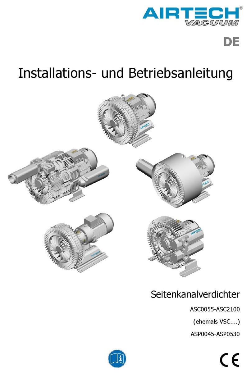
AirTech 3BA Series Manual

Operating and Maintenance Instructions
3BA Regenerative Blowers

2

INSTALLATION & OPERATING MANUAL
3BA REGENERATIVE BLOWERS
Table of Contents
Section:
Page Number:
1. Safety
1.1 General Safety Precautions
1.2 Clothing and Protective Gear
1.3 Electrical Safety
1.4 Vacuum and Gauge Pressure Safety
1.5 Installation/Start-up
1.6 Maintenance Procedures
1.7 Hot Surfaces
1.8 Hearing Protection
1.9 Safety Guidelines for Transport of the unit
4
4
4
4
5
5
6
6
6
7
2
.
Technical Data
8
Table 1: 3 Phase, Single Stage, 50 Hertz 10
Table 2: 3 Phase, Single Stage, 60 Hertz 11
Table 3: 3 Phase, Two/Three Stage, 50 Hertz 12
Table 4: 3 Phase, Two/Three Stage, 60 Hertz 13
Table 5: Single-phase, 50 Hz
Table 6: Single-phase, 60 Hz
Table 7: Single Stage – Approx. Temperature Rise
14
14
16
Table 8: Two/Three Stage – Approx. Temperature Rise 17
Table 9: Tightening Torque Specifications 18
3
. Installation
20
3.1 Installation Procedure
21
4
. Start
-
up
4.1 Start-up Procedure
4.2 Potential Risks For Operators
23
23
23
5
. Maintenance and Servicing
24
5.1 Troubleshooting Chart 25
5.2 Lifting 27
5.3 Storage 28
5.4 Disposal 28
6
.
Exploded
-
View Drawings
29
3BA1 Single-Stage
29
3BA1 Two-Stage 30
3BA1943 Two-Stage 31
3BA7 Single-Stage
32
3BA7 Two-Stage 33
Warranty Statement
34
3

1. Safety
1.1 General Safety Precautions
All personnel should familiarize themselves with the units’ specifications
and be careful not to exceed the unit’s capacity.
Transport, installation, operation, shut-down, maintenance and disposal of
3BA units should be carried out by qualified professionals.
Do not attempt to start or run the unit unless it has been completely
assembled. Particular attention should be paid to: the vacuum
pump/compressor cover, the muffler on the inlet and discharge
connections, and the fan guard.
The standard 3BA unit must never come into contact with flammable
substances.
1.2 Clothing and Protective Gear
It is recommended that all personnel wear proper protective gear while operating
the unit. This may include eye protection, gloves and helmets.
Please be aware that it is possible for hair and clothing to be pulled into the unit.
Avoid wearing loose-fitting clothing near the unit while it is operating and wear a
hairnet if necessary.
1.3 Electrical Safety
Electrical installation should only be done by qualified electricians. Before
doing any electrical work on a 3BA unit, please ensure that power to the unit
has been disconnected. Do not attempt to open the unit’s terminal box until you
have made certain that the unit is not connected to a power source.
The terminal box must be kept free of dirt and moisture at all times. Make sure
the terminal box cover and cable entries are tightly sealed so they remain
dustproof and waterproof. Check the terminal box regularly to make sure it is
sealed and free of debris and moisture.
WARNING: Improper operation of 3BA units can result in serious or
even fatal injuries. Please make sure all personnel have read and
understood this manual before operating the unit.
4

1.4 Vacuum and Gauge Pressure Safety
In order to avoid dangerous situations associated with vacuum and gauge
pressure, please utilize secure mounting elements, connections, lines, fittings,
and containers. Pipes/hoses must be securely connected to the inlet and
discharge connections. The inlet and discharge connections and the pipes/hoses
connected to them must not be closed, clogged, or soiled. Check regularly to
ensure that these connections and mountings are not becoming unseated. If
necessary, support pipes and hoses to ensure that there is no tension on the
connections. Failure to observe these precautions can lead to sudden
evacuation of hazardous fluids or dangerous suction that can pull hair or
clothing into the unit.
1.5 Installation/Start-up
The unit and any lines connected to it must be securely installed. In particular,
the feed pipes must be securely routed, e.g. in cable ducts, in the floor, etc.
If a separate control panel or other such interface will be used to start and stop
the unit, it should be installed in an area with an unobstructed view of the unit to
ensure that it is not switched on while being serviced.
Excess vibration can cause damage to the unit and/or unsafe conditions. Install
the unit on a solid foundation or a solid mounting surface. Check screw
glands/unions for strength and firm seating.
Cables and pipes should be installed in a recess in the floor or duct so they do
not present a tripping hazard.
To ensure sufficient cooling of the unit, ventilation screens and openings must
remain clear. Ensure that discharge air from other units cannot be pulled into the
unit.
Make sure that the inlet and pressure lines are clearly marked to avoid confusion.
Interchanged inlet and pressure lines can lead to damage to the unit and/or
serious injury.
Install a filter in the inlet pipe and replace it regularly. If particulates or debris
enter the unit, the blades of the impellers can be damaged and blades could
potentially break off, potentially creating a hazardous situation.
If re-starting the unit after it has been idle for a long period of time, measure the
insulation resistance of the motor. If values are less than 1 k ȍper volt of nominal
voltage, the winding may be too dry.
5

If the unit is installed or stored in an environment with a temperature of over
104°F (40°C) be aware that the winding may be damaged and the grease might
need to be changed more often.
1.6 Maintenance Procedures
Before beginning work on the pump-motor unit, please take the following
precautions:
• Make sure power has been completely disconnected
• Wait for the unit to come to a complete stop.
• Allow the unit time to cool.
• Shut off lines and release pressure
• Make certain that no vacuum or gauge pressure is present in the lines/tanks to
be opened.
• Make sure that no fluids can escape
Please note that the rotating impeller is accessible when the inlet and discharge
connections are open. Do not reach into the unit through open connections or
insert objects into the unit through any openings. Serious injury could occur. If
the unit is running without piping or tubing, provide the inlet and discharge of the
unit with either additional mufflers or piping of a sufficient length to prevent
access to the impeller.
Check regularly to ensure the terminal box is free of any dirt or foreign
substances and there is no moisture or humidity present. Make certain the
terminal box cover and cable entries are tightly closed.
1.7 Hot Surfaces
During operation, the surface of the unit can reach temperatures of 320°F
(160°C). It is advisable to cover the unit with suitable touch protection (e.g. a
perforated plate or wire cover). Do not touch the unit during operation, and allow
time to cool after shut-down. Temperature-sensitive parts such as lines or
electronic components should not come into contact with the surface of the unit.
1.8 Hearing Protection
Make certain any missing or defective silencers are replaced. Noise emitted by
the unit can cause serious hearing damage. Conduct a noise measurement test
while the unit is running. If the unit operates over 90 dB(A), please place a
warning sign in the area where the unit has been installed and make certain that
6

any personnel working in the vicinity wear ear protection at all times while the
unit is running.
1.9 Safety Guidelines for Transport of the unit:
Prior to transport and handling, please make sure that all components are
properly assembled and secure. Any machinery used to transport these units
must have the proper lifting capacity. Please consult the table on page 27 to find
the weight of the unit being handled. Do not stand or walk under suspended
loads.
If a 3BA unit has come in contact with any dangerous substances, it must
be decontaminated before being sent to Airtech for repair evaluation.
7

2 Technical Data
These operating instructions cover the Airtech 3BA side channel vacuum pumps
and compressors supplied with standard TEFC motors. Other configurations are
available including V-belt driven units, units with explosion proof motors,
mechanical seals, magnetic drives, coatings and modifications for high pressure
service. Airtech can provide any combination of modifications to meet your
application requirements. Such blowers, however, are outside the scope of this
manual.
Description
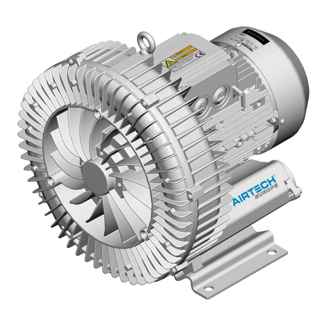
All regenerative blowers are dynamic compression devices and utilize a non-
contacting impeller to accelerate the gas and a specially designed housing to
compress the gas. Cooling is accomplished by using the motor fan to blow air
over the housing. In larger models, the housing is specially designed with
cooling fins to allow a wider range of operation. Both the inlet and outlet ports
have built-in silencers and mesh screens. Both the inlet and outlet have an
inside connection thread corresponding to DIN ISO 228. On larger units, multiple
suction and discharge connection configurations may be available.
The wetted parts are constructed of Aluminum on all models. The blower shares
a bearing with the motor. The seal between the bearing and the motor is not gas
tight in most models, therefore these blowers are not recommended for handling
of toxic or explosive gases. (Contact Airtech Vacuum, Inc. for additional options
if explosive or toxic gases will be handled.)
A full range of accessory items are available, including vacuum or pressure relief
valves, check valves, suction filters, motor starters, vacuum/pressure cross-over
valves, and in-line filters.
Application/Installation Environment
CAUTION! These blowers are designed for use in general industry.
Suitable personnel protection according to OSHA requirements is
provided, but the equipment should not be operated in residential settings.
Airtech blowers can be operated as either vacuum pumps or compressors. They
are suitable for use with air having a relative humidity up to 90 percent, but not
generally suitable for handling corrosive or erosive gases. Special versions for
toxic or aggressive gases may be available. Use of the standard blower in
aggressive environments may cause damage to the blower or exposure to gases
being handled in the local environment.
8

CAUTION! Dangerous (flammable or explosive) or aggressive (corrosive)
gases should not be handled by the standard blower.
Handling of flammable or aggressive gases and vapors may be possible by using
a specially configured or modified blower. Contact factory for additional
information. The standard blower is not suitable for operation in explosive
environments as defined by NFPA 70. Contact factory for assistance.
CAUTION! The ambient and suction temperatures should be between 40
and 105 F. For temperatures outside this region, please contact the
factory.
The maximum permissible pressure difference for vacuum or pressure is
dependant on the motor rating (See Tables 1 to 4 for detailed information by
model number.) and power supply frequency. The figures in Tables 1 to 4 are
computed assuming an ambient temperature of 77 F (25 C) and a local
barometric pressure of 1013 mbar (sea level). Operation at an ambient
temperature of 104 F (40C) is the maximum permissible, and will result in a
reduction of 10 percent on maximum vacuum or pressure attainable by the unit.
For temperatures between 77 F and 104 F, reduce the maximum pressure
reduction is a linear function of temperature.
9

Table 1. Three-phase, Single Stage, 50 Hertz
3BA1300-7AT06 .33/.25 200-240/345-415 2.1/1.2 48/82 -100/100 53
2BA1300-7AT16 .54/.4 200-240/345-415 2.6/1.5 48/82 -120/130 53
3BA1400-7AT06 .94/.7 200-240/345-415 3.8/2.2 84/142 -120/120 63
2BA1400-7AT16 1.15/.85 200-240/345-415 4.2/2.4 84/142 -160/160 63
3BA1400-7AT26 1.75/1.3 200-240/345-415 5.7/3.3 84/142 -170/200 63
3BA1500-7AT06 1.15/.85 200-240/345-415 4.2/2.4 120/204 -100/100 64
3BA1500-7AT16 1.75/1.3 200-240/345-415 5.7/3.3 120/204 -170/170 64
3BA1500-7AT26 2.15/1.6 220-250/415-460 7.5/4.3 120/204 -200/190 64
3BA1500-7AT36 2.96/2.2 200-240/345-415 9.7/5.6 120/204 -220/270 64
3BA1530-7AT16 1.75/1.3 200-240/345-415 5.7/3.3 165/280 -120/110 65
3BA1530-7AT26 2.15/1.6 200-240/345-415 7.5/4.3 165/280 -160/150 65
3BA1530-7AT36 2.96/2.2 200-240/345-415 9.7/5.6 165/280 -220/230 65
3BA1600-7AT06 2.15/1.6 200-240/345-415 8.5/4.9 188/320 -160/150 69
3BA1600-7AT16 2.96/2.2 200-240/345-415 9.7/5.6 188/320 -190/190 69
3BA1600-7AT26 4.04/3.0 200-240/345-415 12.5/7.2 188/320 -260/270 69
3BA1600-7AT36 5.4/4.0 200-240/345-415 13.0/7.5 188/320 -290/360 69
3BA1630-7AT06 2.15/1.6 200-240/345-415 8.5/4.9 240/408 -160/150 69
3BA1630-7AT16 2.96/2.2 200-240/345-415 9.7/5.6 240/408 -190/190 69
3BA1630-7AT26 4.04/3.0 200-240/345-415 12.5/7.2 240/408 -260/270 69
3BA1630-7AT36 5.4/4.0 200-240/345-415 15.6/9.0 240/408 -260/290 69
3BA1800-7AT06 5.4/4.0 200-240/345-415 15.6/9.0 280/476 -200/200 70
3BA1800-7AT16 7.4/5.5 200-240/345-415 23/13.3 280/476 -300/300 70
3BA1800-7AT26 10/7.5 200-240/345-415 29/16.7 280/476 -320/430 70
3BA1830-7AT06 5.4/4 200-240/345-415 15.6/9 400/680 -150/140 76
3BA1830-7AT16 7.4/5.5 200-240/345-415 23/13.3 400/680 -200/190 76
3BA1830-7AT26 10/7.5 200-240/345-415 29/16.7 400/680 -270/260 76
3BA1900-7AT06 10.8/8 200-240/345-415 31.5/18.2 568/965 -190/190 74
3BA1900-7AT16 16.8/12.5 200-240/345-415 48.5/28 568/965 -290/280 74
3BA1900-7AT36 25/18.5 200-240/345-415 64.5/37 568/965 -362/462 74
3BA1930-7AT16 16.8/12.5 200-240/345-415 48.5/28 744/1264 -290/280 71
3BA1930-7AT36 25/18.5 200-240/345-415 64.5/37 744/1264 -310/310 71
3BA7310-0AT167 .75/.55 200-240/345-415 2.8/1.6 40/68 -250/250 57
3BA7410-0AT167 1.5/1.1 200-240/345-415 5.4/3.1 50/84 -300/380 58
3BA7510-0AT168 2/1.5 200-240/345-415 7.5/4.3 70/120 -370/650 64
3BA7510-0AT268 3/2.2 200-240/345-415 9.7/5.6 70/120 -310/430 64
3BA7610-0AT168 3/2.2 200-240/345-415 9.7/5.6 96/163 -310/430 65
3BA7610-0AT368 4.4/3.3 200-240/345-415 13/7.5 96/163 -500/750 65
Model
Voltage Motor
Current
(Amps)
Maximum
Pressure
(mbar)
Sound
Pressure
Level (dBA)
Rated
Power
HP/kW
Open Flow
Capacity
CFM/m3/hr
10

Table 2. Three-phase, Single-stage, 60 Hz
When operating at altitudes above 3280 feet (1000 m) above mean sea level, contact Airtech Inc.
CAUTION! Operation of the unit outside the recommended range of
pressures and ambient conditions will result in shorted operating life.
3BA1300-7AT06 .39/.29 220-250/415-460 1.74/1.0 60/102 -100/100 56
2BA1300-7AT16 .67/.5 220-250/415-460 2.6/1.5 60/102 -150/160 56
3BA1400-7AT06 1.12/.83 220-250/415-460 3.75/2.15 105/179 -130/130 64
3BA1400-7AT16 1.28/.95 220-250/415-460 4.35/2.5 105/179 -160/160 64
3BA1400-7AT26 2/1.5 220-250/415-460 5.5/3.2 105/179 -210/200 64
3BA1500-7AT06 1.28/.95 220-250/415-460 4.35/2.5 150/255 -80/70 70
3BA1500-7AT16 2/1.5 220-250/415-460 5.5/3.2 150/255 -150/140 70
3BA1500-7AT26 2.7/2.05 220-250/415-460 7.5/4.4 150/255 -220/210 70
3BA1500-7AT36 3.4/2.55 220-250/415-460 9.0/5.3 150/255 -260/290 70
3BA1530-7AT16 2/1.5 220-250/415-460 5.7/3.3 200/340 -90/80 71
3BA1530-7AT26 2.7/2.05 220-250/415-460 7.6/4.4 200/340 -260/270 70
3BA1530-7AT36 3.4/2.55 220-250/415-460 10.3/6.0 200/340 -260/250 70
3BA1600-7AT06 2.7/2.05 220-250/415-460 7.5/4.4 235/400 -160/150 72
3BA1600-7AT16 3.4/2.55 220-250/415-460 9.0/5.3 235/400 -190/190 72
3BA1600-7AT26 4.6/3.45 220-250/415-460 12.0/6.5 235/400 -240/230 72
3BA1600-7AT36 6.1/4.6 220-250/415-460 15.2/8.5 235/400 -320/310 72
3BA1630-7AT06 2.7/2.05 220-250/415-460 7.5/4.4 300/510 -160/150 72
3BA1630-7AT16 3.4/2.55 220-250/415-460 9.0/5.3 300/510 -190/190 72
3BA1630-7AT26 4.6/3.45 220-250/415-460 12.0/6.5 300/510 -240/230 72
3BA1630-7AT36 6.1/4.6 220-250/415-460 15.2/8.5 300/510 -260/260 72
3BA1800-7AT06 6.1/4.6 220-250/415-460 15.2/8.5 350/595 -160/160 74
3BA1800-7AT16 8.4/6.3 220-250/415-460 20/11.2 350/595 -300/280 74
3BA1800-7AT26 11.5/8.6 220-250/415-460 27.5/15 350/595 -350/400 74
3BA1830-7AT06 6.2/4.6 220-250/415-460 15.2/8.5 500/850 -90/90 79
3BA1830-7AT16 8.4/6.3 220-250/415-460 20/11.2 500/850 -180/180 79
3BA1830-7AT26 11.5/8.6 220-250/415-460 27.5/15 500/850 -270/260 79
3BA1900-7AT06 12.1/9 220-250/415-460 31.5/18.2 710/1207 -150/140 79
3BA1900-7AT16 19.5/14.5 220-250/415-460 50/29 710/1207 -270/260 79
3BA1900-7AT36 28.7/21.3 220-250/415-460 68/39 710/1207 -382/422 79
3BA1930-7AT16 19.5/14.5 220-250/415-460 50/29 930/1581 -270/260 75
3BA1930-7AT36 28.7/21.3 220-250/415-460 68/39 930/1581 -300/280 75
3BA7210-0AT167 1.1/.83 220-250/415-460 3.75/2.15 35/60 -270/320 62
3BA7310-0AT167 1.1/.83 220-250/415-460 3.75/2.15 48/82 -260/250 62
3BA7410-0AT167 2/1.5 220-250/415-460 5.5/3.2 60/102 -340/370 62
Model Voltage
Motor
Current
(Amps)
Maximum
Pressure
(mbar)
Sound
Pressure
Level (dBA)
Rated
Power
HP/kW
Open Flow
Capacity
CFM/m3/hr
11

3BA1310-7AT26 .94/.7 200-240/345-415 3.8/2.2 48/81.6 -120/120 55
3BA1410-7AT36 2.15/1.6 200-240/345-415 7.5/4.3 84/142.8 -200/190 66
3BA1410-7AT46 2.96/2.2 200-240/345-415 9.7/5.6 84/142.8 -320/420 66
3BA1510-7AT46 4.04/3.0 200-240/345-415 12.5/7.2 121.6/206.7 -340/410 72
3BA1510-7AT56 5.39/4.0 200-240/345-415 17.4/10 121.6/206.7 -390/440 72
3BA1610-7AT36 2.9/2.2 200-240/345-415 9.7/5.6 188/319.6 -190/190 73
3BA1610-7AT26 4.04/3.0 200-240/345-415 12.5/7.2 188/319.6 -260/270 73
3BA1610-7AT36 5.39/4.0 200-240/345-415 13.0/7.5 188/319.6 -290/360 73
3BA1610-7AT46 7.41/5.5 200-240/345-415 23/13.3 188/319.6 -420/500 73
3BA1610-7AT56 10.1/7.5 200-240/345-415 29/16.7 188/319.6 -420/610 73
3BA1640-7AT36 5.39/4.0 200-240/345-415 13.0/7.5 280/476 -290/360 74
3BA1640-7AT46 7.41/5.5 200-240/345-415 23/13.3 280/476 -420/500 74
3BA1640-7AT56 10.1/7.5 200-240/345-415 29/16.7 280/476 -420/610 74
3BA1810-7AT16 7.4/5.5 200-240/345-415 23/13.3 280/476 -420/500 74
3BA1810-7AT26 10.1/7.5 200-240/345-415 29/16.7 280/476 -320/430 74
3BA1810-7AT36 14.8/11 200-240/345-415 29/16.7 280/476 -430/600 74
3BA1810-7AT46 20.2/15 200-240/345-415 56.5/32.5 280/476 -460/670 74
3BA1840-7AT26 10.1/7.5 200-240/345-415 29.0/16.7 280/476 -320/430 74
3BA1840-7AT36 14.8/11.0 200-240/345-415 48.5/28.0 280/476 -430/600 74
3BA1910-7AT16 16.8/12.5 200-240/345-415 48.5/28 624/1061 -290/280 74
3BA1910-7AT36 26.95/20.0 200-240/345-415 69/40 624/1061 -443/502 74
3BA1910-7AT46 33.51/24.98 200-240/345-415 90/52 624/1061 -443/592 84
3BA19437AT26 20.1/15 200-240/345-415 59/34 1200/2040 -160/170 75
3BA19437AT36 26.8/20 200-240/345-415 69/40 1200/2040 -250/230 75
3BA19437AT46 33.5/25 200-240/345-415 90/52 1200/2040 -310/280 75
3BA7220-0AT567 2/1.5 200-240/345-415 7.5/4.3 28/48 -370/650 58
3BA7320-0AT467 1.5/1.1 200-240/345-415 5.4/3.1 40/68 -300/380 58
3BA7320-0AT567 2/1.5 200-240/345-415 7.5/4.3 40/68 -480/450 59
3BA7420-0AT267 2/1.5 200-240/345-415 7.5/4.3 50/84 -480/450 61
3BA7420-0AT567 4.4/3.3 200-240/345-415 13/7.5 50/84 -500/750 61
3BA7520-0AT268 3/2.2 200-240/345-415 9.7/5.6 70/120 -470/460 64
3BA7620-0AT368 4.4/3.3 200-240/345-415 13/7.5 96/163 -500/750 68
3BA7620-0AT468 5.4/4 200-240/345-415 14/8.1 96/163 -370/650 67
3BA7620-0AT568 7.5/5.5 200-240/345-415 19.9/11.5 96/163 -520/750 68
3BA7630-0AT668 10.1/7.5 200-240/345-415 29/16.7 96/163 -420/610 77
Model Voltage
Motor
Current
(Amps)
Maximum
Pressure
(mbar)
Sound
Pressure
Level (dBA)
Rated Power
HP/kW
Open Flow
Capacity
CFM/m3/hr
Table 3. 3 Phase, Two/Three Stage, 50 Hertz
12

Table 4. 3 Phase, Two/Three Stage, 60 Hertz
3BA1310-7AT26 1.11/.83 220-250/415-460 3.75/2.15 60/102 -130/130 61
3BA1410-7AT36 2.7/2.05 220-250/415-460 7.5/4.4 105/179 -220/210 69
3BA1410-7AT46 3.4/2.55 220-250/415-460 9.0/5.3 105/179 -350/440 69
3BA1510-7AT46 4.6/3.45 220-250/415-460 12.0/6.5 152/258 -380/360 74
3BA1510-7AT56 6.1/4.6 220-250/415-460 15.2/8.5 152/258 -410/480 74
3BA1610-7AT36 3.4/2.55 220-250/415-460 9.0/5.3 235/400 -190/190 76
3BA1610-7AT26 4.6/3.45 220-250/415-460 12.0/6.5 235/400 -240/230 76
3BA1610-7AT36 6.4/4.8 220-250/415-460 16.5/9.8 235/400 -320/310 76
3BA1610-7AT46 8.4/6.3 220-250/415-460 20/11.2 235/400 -440/440 76
3BA1610-7AT56 11.5/8.6 220-250/415-460 27.5/15.0 235/400 -440/670 76
3BA1640-7AT36 6.1/4.6 220-250/415-460 15.2/8.5 350/595 -320/310 78
3BA1640-7AT46 8.4/6.3 220-250/415-460 20.0/11.2 350/595 -440/440 78
3BA1640-7AT56 11.5/8.6 220-250/415-460 27.5/15.0 350/595 -440/670 78
3BA1810-7AT16 8.4/6.3 220-250/415-460 20.0/11.2 350/595 -440/440 78
3BA1810-7AT26 11.5/8.6 220-250/415-460 27.5/15.0 350/595 -350/400 78
3BA1810-7AT36 17/12.6 220-250/415-460 50.2/29.0 350/595 -460/600 78
3BA1810-7AT46 23.3/17.3 220-250/415-460 60.0/34.5 350/595 -490/750 78
3BA1840-7AT26 11.5/8.6 220-250/415-460 27.5/15.0 350/595 -350/400 78
3BA1840-7AT36 17/12.6 220-250/415-460 50.2/29.0 350/595 -460/600 78
3BA1910-7AT16 19.5/14.5 220-250/415-460 50.0/29.0 780/1326 -270/260 84
3BA1910-7AT36 31/23 220-250/415-460 72 /42 780/1326 -443/433 84
3BA1910-7AT46 38.9/28.9 220-250/415-460 90/52 780/1326 -443/542 84
3BA19437AT26 23.4/17.5 220-250/415-460 63/36.5 1440/2447 -120/110 84
3BA19437AT36 30.8/23 220-250/415-460 72/42 1440/2447 -190/180 84
3BA19437AT46 38.8/28.9 220-250/415-460 90/52 1440/2447 -265/230 84
3BA7220-0AT567 2.7/2.05 220-250/415-460 7.5/4.4 35/60 -500/740 62
3BA7320-0AT467 2/1.5 220-250/415-460 5.5/3.2 48/82 -340/370 63
3BA7320-0AT567 2.7/2.05 220-250/415-460 7.5/4.4 48/82 -430/410 63
3BA7420-0AT267 2.7/2.05 220-250/415-460 7.5/4.4 60/102 -430/410 66
3BA7420-0AT567 5.1/3.8 220-250/415-460 13.5/7.8 60/102 -510/850 66
3BA7520-0AT268 3.4/2.55 220-250/415-460 9/5.3 84/143 -500/450 70
3BA7620-0AT368 5.1/3.8 220-250/415-460 13.5/7.8 115/196 -510/850 71
3BA7620-0AT468 6.1/4.6 220-250/415-460 15.2/8.5 115/196 -480/500 71
3BA7620-0AT568 8.4/6.6 220-250/415-460 22.5/12.6 115/196 -520/820 72
3BA7630-0AT668 11.5/8.6 220-250/415-460 27.5/15 115/196 -440/670 80
Model Voltage
Motor
Current
(Amps)
Maximum
Pressure
(mbar)
Sound
Pressure
Level (dBA)
Open Flow
Capacity
CFM/m3/hr
Rated
Power
HP/kW
13

Table 5. Single Phase, 50 Hertz
Table 6. Single Phase, 60 Hertz
3BA1100-7AS05 0.27/0.2 230 1.45 24/40 -60/70 50
3BA1200-7AS05 0.33/0.25 115/230 3.5/1.7 35/60 -100/100 50
3BA1300-7AS15 0.5/0.37 115/230 5.4/2.7 48/82 -110/110 53
3BA1330-7AS15 0.5/0.37 115/230 5.4/2.7 60/102 -110/110 54
3BA1400-7AS25 1.47/1.09 115/230 13/6.5 84/142 -149/189 64
3BA1410-7AS25 2/1.49 115/230 22/11 84/142.8 -279/259 66
3BA1500-7AS35 2/1.49 115/230 22/11 120/204 -189/199 64
3BA7210-0AS75 0.74/0.55 115/230 13/6.5 28/48 -229/289 57
3BA7220-0AS75 2/1.49 115/230 19.4/9.7 29/49 -371/600 57
3BA7310-0AS75 1.26/0.93 115/230 15.2/7.6 40/68 -249/351 58
3BA7320-0AS75 2/1.49 115/230 19.4/9.7 40/68 -401/550 59
3BA7410-OAS45 1.47/1.09 115/230 13/6.5 50/84 -299/381 59
Sound
Pressure
Level (dBA)
Model
Rated
Power
HP/kW
Voltage
Motor
Current
(Amps)
Open Flow
Capacity
CFM/m3/hr
Maximum
Pressure
(mbar)
3BA1100-7AS05 0.31/0.23 230 1.3 30/51 -75/80 53
3BA1200-7AS05 0.38/0.28 115/230 5/2.8 48/82 -112/112 53
3BA1300-7AS15 0.6/0.44 115/230 6.0/3.0 60/102 -130/139 56
3BA1330-7AS15 0.6/0.44 115/230 6.0/3.0 74/126 -130/139 57
3BA1400-7AS25 1.74/1.29 115/230 14.0/7.0 105/179 -179/189 64
3BA1410-7AS25 2.35/1.75 115/230 24.0/12.0 105/179 -249/229 69
3BA1500-7AS35 2.35/1.75 115/230 24.0/12.0 150/255 -179/179 70
3BA7210-0AS75 0.84/0.63 115/230 14.2/7.1 35/60 -259/309 62
3BA7220-0AS75 2.35/1.75 115/230 20.6/10.3 35/60 -421/660 62
3BA7310-0AS75 1.47/1.09 115/230 18.0/9.0 48/82 -279/391 62
3BA7320-0AS75 2.35/1.75 115/230 20.6/10.3 48/82 -391/541 63
3BA7410-OAS45 1.74/1.29 115/230 14.0/7.0 60/102 -338/391 62
Sound
Pressure
Level (dBA)
Model
Rated
Power
HP/kW
Voltage
Motor
Current
(Amps)
Open Flow
Capacity
CFM/m3/hr
Maximum
Pressure
(mbar)
14

Operation of any blower is possible at 87 Hertz without modification in most
cases. When using a VFD to operate the blower at this frequency, refer to the
nameplate for limits on vacuum and pressure, current draw and motor
performance.
If your specific model number is not listed above, please consult the nameplate
on the unit for electrical data. If the model you are installing is listed above,
please confirm the data on the nameplate. Data in Tables 1 through 4 is subject
to change and is approximate. Be sure to confirm necessary operating data what
that on the nameplate before commissioning the unit.
CAUTION! Do not operate any 3BA blower above 87 Hz without
consultation with the factory. Failure of the blower motor is possible when
operating out of range. Consult with the factory for assistance.
15

Expected temperature rise of the handled gas at maximum allowable pressure
differential and when operating at sea level is indicated below:
Table 7: Single Stage – Approximate Temperature Rise
Blower Model Maximum Rise at 50 Hz speed Maximum Rise at 60 Hz speed
Degrees F Degrees C Degrees F Degrees C
3BA1100-7..0. 115 64 136 76
3BA1200-7..0. 65 36 101 56
3BA1300-7..0. 90 50 77 43
3BA1300-7..1. 90 50 140 78
3BA1300-7..2. 90 50 158 88
3BA1400-7..0. 99 55 86 48
3BA1400-7..1. 129 72 122 68
3BA1400-7..2. 149 83 167 93
3BA1500-7..0. 86 48 72 40
3BA1500-7..1. 115 64 97 54
3BA1500-7..2. 138 77 122 68
3BA1500-7..3. 203 113 180 100
3BA1500-7..6. 248 138 248 138
3BA1600-7..0. 81 45 68 38
3BA1600-7..1. 145 81 104 58
3BA1600-7..2. 171 95 176 98
3BA1600-7..3. 225 125 185 103
3BA1600-7..6. 248 138 194 108
3BA1600-7..7. 248 138 248 138
3BA1800-7..0. 104 58 104 58
3BA1800-7..1. 153 85 185 103
3BA1800-7..2. 248 138 221 123
3BA1900-7..0. 97 54 95 53
3BA1900-7..1. 182 101 155 86
3BA1900-7..3. 230 128 212 118
3BA1943-7..2. 85 47 75 42
3BA1943-7..3. 130 72 100 56
3BA1943-7..4. 180 100 140 78
3BA7210-0..1.. 126 70 142 79
3BA7310-0..1.. 142 79 142 79
3BA7310-0..2.. 178 99 187 104
3BA7410-0..1.. 194 108 214 119
3BA7510-0..1.. 199 111 232 129
3BA7510-0..2.. 248 138 234 130
3BA7610-0..1.. 244 136 255 142
3BA7610-0..3.. 244 136 255 142
16

Table 8: Two/Three Stage – Approximate Temperature Rise
Blower Model
Maximum Rise
at 50 Hz speed
Maximum Rise
at 60 Hz speed
Degrees F Degrees C Degrees F Degrees C
3BA1310-7..2. 127 71 165 92
3BA1410-7..3. 154 86 149 83
3BA1410-7..4. 181 101 180 100
3BA1510-7..4. 190 106 176 98
3BA1510-7..5. 194 108 201 112
3BA1610-7..1. 92 51 86 48
3BA1610-7..2. 129 72 118 66
3BA1610-7..3. 176 98 167 93
3BA1610-7..4. 221 123 190 106
3BA1610-7..5. 246 137 266 148
3BA1610-7..7. 176 98 167 93
3BA1610-7..8. 176 98 248 138
3BA1810-7..1. 113 63 80 45
3BA1810-7..2. 185 103 140 78
3BA1810-7..3. 248 138 248 138
3BA1910-7..1. 119 66 115 64
3BA1910-7..2. 203 113 169 94
3BA1910-7..3. 248 138 274 152
3BA1910-7..4. 248 138 274 152
3BA7220-0..2.. 131 73 171 95
3BA7220-0..5.. 165 92 230 128
3BA7320-0..5.. 178 99 255 142
3BA7420-0..2.. 192 107 176 98
3BA7420-0..5.. 250 139 243 135
3BA7520-0..2.. 192 107 216 120
3BA7520-0..7.. 257 143 230 128
3BA7620-0..3.. 255 142 259 144
3BA7620-0..5.. 255 142 262 146
3BA7630-0..6.. 248 138 248 138
17

Table 9: Tightening Torque Specifications
For non-electrical connections
Thread Ft-lbs maximum torque Nm maximum torque
M4 2.43 3.3
M5 3.25 4.4
M6 6.49 8.8
M8 19.47 26.4
M10 34.10 46.2
M12 56.76 77
For electrical connections
Thread Ft-lbs torque Nm torque
M4 0.6 to 0.9 0.8 to 1.2
M5 1.3 to 1.8 1.3 to 1.8
For metal threaded glands/unions
Thread Ft-lbs maximum torque Nm maximum torque
M12x1.5 3 to 4.5 4 to 6
M16x1.5 3.7 to 5.5 5 to 7.5
M20x1.5 4.4 to 6.6 6 to 9
M32x1.5 5.9 to 8.9 8 to 12
M40x1.5 5.9 to 8.9 8 to 12
For plastic threaded glands/unions
Thread Ft-lbs maximum torque Nm maximum torque
M12x1.5 1.5 to 2.6 2 to 3.5
M16x1.5 2.2 to 3 3 to 4
M20x1.5 3 to 3.7 4 to 5
M32x1.5 3.7 to 5.2 5 to 7
M40x1.5 3.7 to 5.2 5 to 7
18

Operating above the indicated maximum pressure or vacuum would overload the
motor and/or overheat the unit. In addition to the maximum allowable pressure
difference, careful consideration should be given to matching the motor
protection devices (provided by others) to the expected current draw. In no case
should the blower be operated with inadequate motor overload protection.
Since regenerative blowers are dynamic compression devices, the performance
limits shown in Tables 1 to 4 are applicable only for a gas with the same specific
gravity, dynamic viscosity and chemical characteristics as air. For gases with
different physical properties than air, the limits will be different from those shown
in the tables. Please contact Airtech for assistance in determining the proper
blower size and configuration if handling gases other than air.
A vacuum relief valve or pressure relief valve should always be installed at the
suction or discharge of the regenerative blower. This will prevent operation
outside the applicable ranges shown in Tables 1 to 4. If the relief valves were
not specified in the ordering process, please contact Airtech for details, price and
availability of the needed valves before commissioning the unit. Failure to use
the proper relief valve may result in failure of the blower due to operation outside
the applicable limits; any such failure is outside the scope of Airtech’s standard
warranty.
WARNING! Be sure to install the necessary personnel protection devices if
unexpected shut-down of the unit presents danger of death or injury.
19

3. Installation
As illustrated in Figure 1, the Airtech 3BA blower can be installed in any physical
configuration.
CAUTION! Regenerative blowers can have surface temperatures in excess
of 320°F. To avoid burns or other physical injury, take care to avoid
contact with the surfaces of the blower during and immediately after
operation.
To ensure adequate cooling of the blower during operation, install the blower with
the minimum clearance as indicated in the table below.
Minimum installation clearances, 3BA blowers
Range Distance from fan guard
to closest obstruction.
(inches/mm)
Distance from cover
(opposite of fan) to
closest obstruction.
(inches/mm)
3BA11 through 3BA14 1.4/34 0.79/20
3BA15 through 3BA19 2.1/53 1.57/40
3BA72 and 3BA73 1.3/34 1.18/30
3BA74 through 3BA76 2.1/54 1.18/30
Please note that it may be desirable, where possible, to allow for larger
clearances to allow access for maintenance or repair personnel. The noted
clearances are to ensure adequate air flow for cooling only and are a minimum
requirement.
Failure to allow for the noted clearances may result in premature failure of the
blower due to lack of cooling, even if all other precautions are taken as
recommended. For specific advice about installations requiring closer
clearances, please contact Airtech, Inc. for recommendations.
Airtech regenerative blowers can be mounted in any configuration, either
horizontally or vertically mounted. It is not usually necessary to bolt the smaller
blowers to a rigid surface during operation, though this may be desirable to
reduce pipe vibration, movement and noise. Larger models should be bolted in
place, especially when installed vertically, to prevent possible rotation, damage
or injury due to start-up torque.
CAUTION! For installations at altitudes greater than 3250 Feet above sea
level there will be a loss in capacity. Please contact your factory
representative for assistance in determining the extent of the loss of
capacity likely at your specific location.
20
This manual suits for next models
62
Table of contents
Other AirTech Blower manuals
Popular Blower manuals by other brands

PayandPack
PayandPack Durablow GFK-160 installation instructions

Lennox Hearth Products
Lennox Hearth Products 775202M installation instructions

Weed Eater
Weed Eater 2510 Operator's manual

Ego Power+
Ego Power+ LB5300 Operator's manual

Shindaiwa
Shindaiwa EB262 Operator's manual

Poulan Pro
Poulan Pro 530163808 instruction manual