AirTest TR-1000 Manual

4-20 mA SENSOR / TRANSMITTER
MODEL TR-1000
Operations & Maintenance Manual
Vehicle Exhaust Detection Applications

2
INSTALLATION AND CALIBRATION
4 – 20 mA SENSOR / TRANSMITTER MODEL TR-1000
INSTALLATION:
1. Locate a flat surface to mount the enclosure so that the sensor can face
downward. If the rear power entry is to be used, remove the plug before
mounting the enclosure. The second power entry is at the end opposite
the sensor.
2. Remove the cover of the enclosure by removing the 4 screws in the
corners. Be careful here since the circuit board is connected to the cover.
The circuit board is connected to the sensor, so the cover will hang from
these wires when removed. Remove the plug from the end power entry if it
is to be used.
3. Connect the electrical fittings to the enclosure and bring in the electrical
wires. NOTE: BE SURE WIRING IS DONE ACCORDING TO THE LOCAL
ELECTRICAL CODE REQUIREMENTS. NOTE: To prevent shorting
problems do not leave ground wire to box bare (if one is used) – cover
with electrical tape.
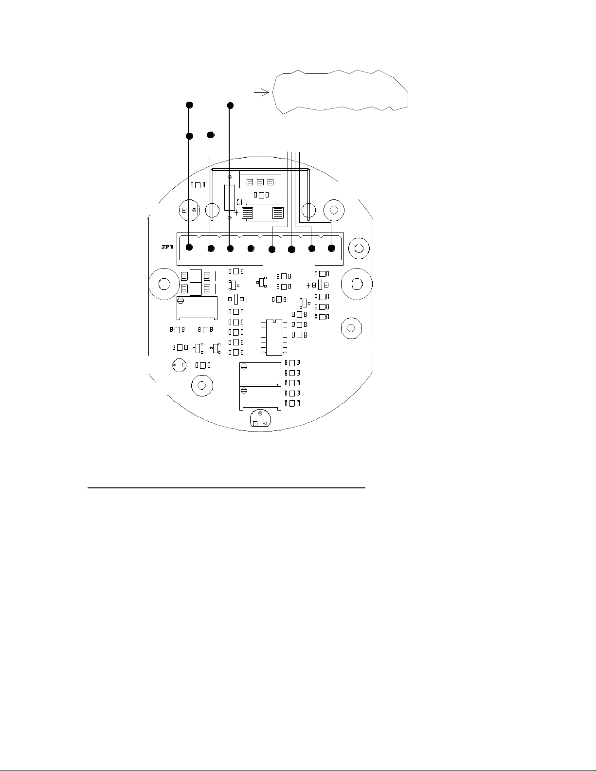
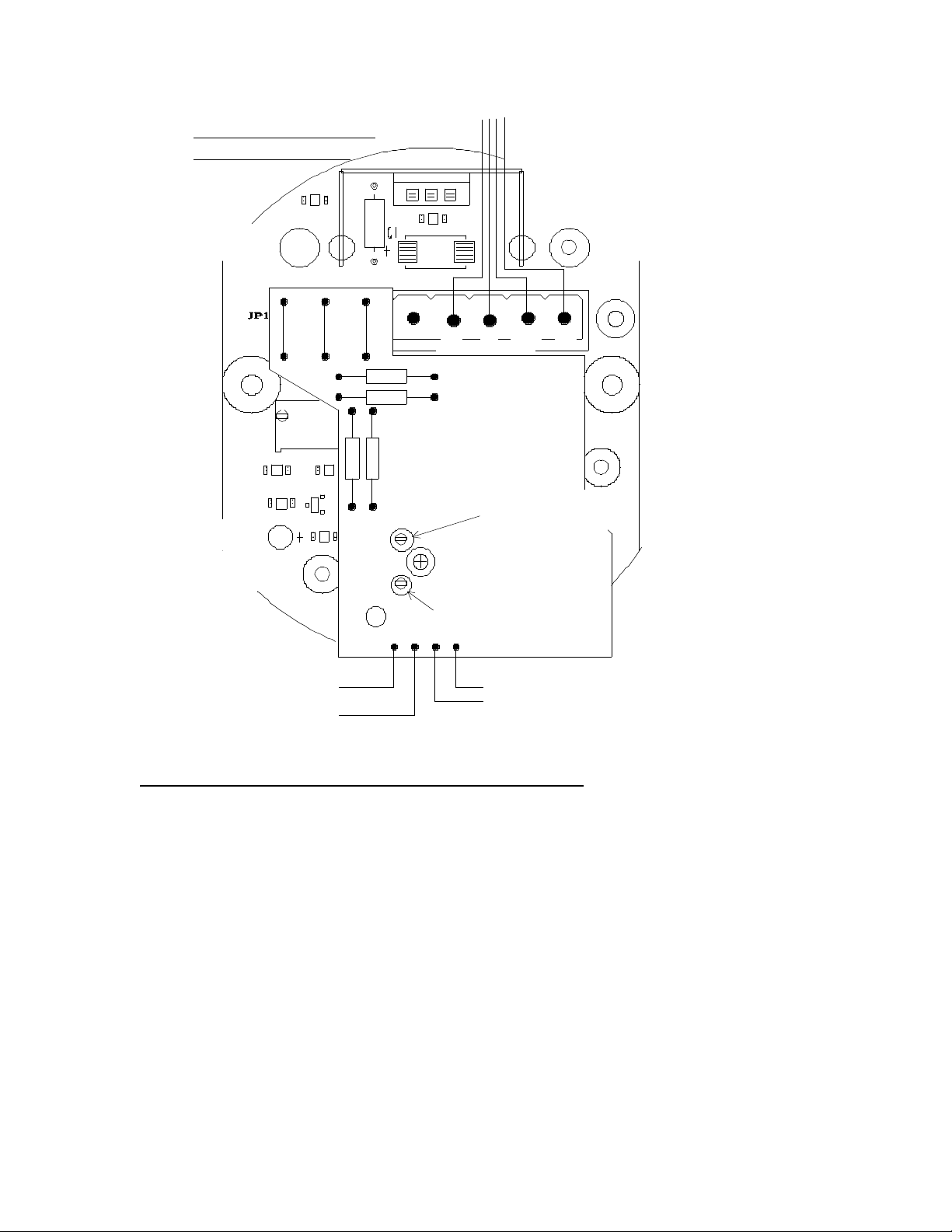
4. Connect the wires to the removable connector block as shown on the
wiring drawing. (See Fig.1)
CALIBRATION - SOLID STATE SENSORS:
The TR-1000 has been factory calibrated for a range of 0 – 400 ppm CO and is
ready for use. If however there is a level of background gases, it should be
calibrated on site. If the range is to be changed, the TR-1000 must be re-
calibrated.
1. Connect power and signal return wires to a suitable controller that will provide
sensor excitation and signal processing. (See Fig.1)
For all the following readings TP1 (RED) is the COMMON POSITIVE jack.
2. Power up the unit, the ready light will come on in 10 seconds. Check TP2
(Black) for correct voltage of 5.0V ±0.1V. If it is satisfactory let the sensor
burn-in for 24 hours. If voltage is unsatisfactory the board is faulty and must
be serviced.
3. TO SET ZERO
Adjust the ZERO potentiometer, RV1, until the ACTIVE LED (YELLOW) just
goes off.

3
4. TO SET ZERO OFFSET
Before proceeding, it is critical that the sensor is exposed to clean air. If
clean air cannot be assured, a sample of clean air, or “Zero” gas should be
applied to the sensor. Monitor the OUTPUT test point - TP3 (Yellow) - and
adjust the ZERO OFFSET potentiometer - RV3 - so the meter reads 0.4 volts
(this is equivalent to 4 mA).
NOTE: The 4 to 20 mA loop must be complete.
5. TO SET SPAN
While still monitoring the OUTPUT test point - TP3 (Yellow), apply a sample
of gas consisting of the target gas mixed with air. The concentration of the
gas should be the same as the desired full scale of the TR-1000.The flow rate
of the gas must be 0.2 liters/minute. Adjust the “GAIN” trimpot - RV2 – so the
meter reads 2.0 volts. (This is equivalent to 20 mA)
The sensor is now calibrated for “zero” and “span”.
It is recommended that sensor calibration be carried out on an annual basis.
NOTE: THESE SENSORS VARY WITH HUMIDITY, PROTECT THE SENSOR
FROM WIND AND AIRFLOWS.

4
FIG.1.
INDICATORS, TEST POINTS & POTENTIOMETERS
A. The ready, green LED, indicates that power has been correctly applied.
B. The active, yellow LED
When “ON” indicates the sensor output is in the active area.
When ”OFF” indicates the sensor output is below zero or overrange.
C. Test Points are:
TP1 (Red) -COMMON reference point for TP2,TP3 & TP4, voltmeter
POSITIVE connection.
TP2 (Black) 5V ±0.1v, circuit power.
TP3 (Yellow) -OUTPUT VOLTAGE, 0.4 to 2.0 volts (equates to 4-20 mA).
TP4 (White) -SIGNAL test point, typically 0.0 to 1.6 volts.
D. Potentiometers:
RV1 -ZERO potentiometer
RV2 -GAIN potentiometer
RV3 -ZERO OFFSET potentiometer
C7
R16
R17
R18
R19
Z1
R15
C4
R11
R10
C3
R9 U1
R12
Q4Q5
R14
R13
LD2
D3
C8
R22
R7
R20
R21
C6
R6
R4
R5
C5
DP1
R8
Q2
R3
Q1
D1
D2
R2
HS1 VR1
R1 C2
V- A V+
TP4
TP1
TP2
TP3
LD1
10-30VDC INPUT POWER
TO CONTROLLER
+
-
SIG
4-20mA
OUTPUT
(BLACK)
(WHITE)
(RED)
RV2
RV3
RV1
(GREEN)
(YELLOW)
READY LED
ACTIVE LED
(YELLOW)
(WIRE COLOURS)
G B W R
(Shielded wire - 3x18 ga. min.)
SENSOR WIRING
IF YOU HAVE THE 24VAC
POWER OPTION GOTO PAGE 7
FOR CORRECT WIRING DIAGRAM

5
SPECIFICATIONS FOR
4-20 mA SENSOR / TRANSMITTER MODEL TR-1000
WEIGHT: 356 grams (12.6 oz.)
SIZE: 175mm 70mm x 60mm
(7”L x 2.75”W x 2.4”D)
POWER: 12 – 30 VDC, 24VAC
SENSOR: Solid state, metal oxide
TRANSMITTER OUTPUT 4 – 20 mA
AirTest continues to work on product improvement, therefore, specifications are subject to
change without notice.
WARRANTY
ATI AirTest Technologies, Inc ( the company) warrants the Model CT-1000,
Carbon Monoxide, Propane and Refrigerant Detector to be free from defects in
materials and workmanship under normal use and service for a period of one
year. The company’s obligation of this warranty shall be limited to the repair or
replacement of any part found to be defective. The company shall not be
obligated to repair or replace units that are found to be in need of repair because
of damage, (other than normal wear and tear), tampering or modification. The
detector must be returned to AirTest suitably packaged and with freight prepaid.
Liability is limited to the replacement cost of a new unit. In no case shall the
company be liable for any consequential or incidental damages however caused.
No agent, dealer or employee of the company has the authority to increase or
alter the obligations or limitations of this warranty.

6
INDICATORS, TEST POINTS & POTENTIOMETERS
A. The ready, green LED, indicates that power has been correctly applied.
B. The active, yellow LED
When “ON” indicates the sensor output is in the active area.
When ”OFF” indicates the sensor output is below zero or overrange.
C. Test Points are:
TP1 (Red) -COMMON reference point for TP2,TP3 & TP4, voltmeter
POSITIVE connection.
TP2 (Black) -MINUS 5V ±0.1v, circuit power.
TP3 (Yellow) -OUTPUT VOLTAGE, 0.4 to 2.0 volts (equates to 4-20 mA).
TP4 (White) -SIGNAL test point, typically 0.0 to 1.6 volts.
D. Potentiometers:
RV1 -ZERO potentiometer
RV2 -GAIN potentiometer
RV3 -ZERO OFFSET potentiometer
Q5
R14
R13
LD2
R2
HS1 VR1
R1 C2
TP3
LD1
RV1
(GREEN)
(YELLOW)
G B WR
RV2Below
RV3Below
(Accessible thro hole)
AC
AC 24 VAC INPUT Power
4-20mA
OUTPUT
4-20 mA
LOOP RETURN
SIGNAL to Controller
( wire - 2 x 18 ga )
ACTIVE LED
(YELLOW)
READY LED
TP2
(RED)
TP1
(BLACK)
(WHITE)
TP4
SENSOR WIRING
AC AC
GND/REF
4-20Ma
output
RED
GREEN
WHITE
BLACK
IF ORDERED WITH
24VAC OPTION
(AC/DC ADAPTER BOARD)
Table of contents
Other AirTest Accessories manuals
Popular Accessories manuals by other brands

elero
elero Lumo-868 operating instructions

PCB Piezotronics
PCB Piezotronics ICP W138A01/038CY020AC Installation and operating manual

Philips
Philips HF3550/02 Important information

Baader
Baader ASTF instruction manual

SICK
SICK MRS1000 operating instructions

HP
HP L1510 - 15 Inch LCD Monitor installation guide

Maxell
Maxell MPC-R5200 user manual

Niles
Niles Flush-Mount IR MicroSensor MS110 Installation and operation guide

Commodore
Commodore Trojan Lightpen user manual

Focusrite
Focusrite Scarlett 2i2 user guide

Fiamma
Fiamma F35 Pro Series Installation and use instructions

ROSE DISPLAYS
ROSE DISPLAYS ANOMULTI SQUARE WITH MULTICLIPS instruction sheet